EP1266558A2 - Convoyeur élévateur muni d'un capteur de force pour détecter le débit d' une moissonneuse-bateuse - Google Patents
Convoyeur élévateur muni d'un capteur de force pour détecter le débit d' une moissonneuse-bateuse Download PDFInfo
- Publication number
- EP1266558A2 EP1266558A2 EP02005835A EP02005835A EP1266558A2 EP 1266558 A2 EP1266558 A2 EP 1266558A2 EP 02005835 A EP02005835 A EP 02005835A EP 02005835 A EP02005835 A EP 02005835A EP 1266558 A2 EP1266558 A2 EP 1266558A2
- Authority
- EP
- European Patent Office
- Prior art keywords
- signal
- crop
- combine
- feeder
- drum
- Prior art date
- Legal status (The legal status is an assumption and is not a legal conclusion. Google has not performed a legal analysis and makes no representation as to the accuracy of the status listed.)
- Granted
Links
Images

Classifications
-
- A—HUMAN NECESSITIES
- A01—AGRICULTURE; FORESTRY; ANIMAL HUSBANDRY; HUNTING; TRAPPING; FISHING
- A01D—HARVESTING; MOWING
- A01D41/00—Combines, i.e. harvesters or mowers combined with threshing devices
- A01D41/12—Details of combines
- A01D41/127—Control or measuring arrangements specially adapted for combines
Definitions
- the invention relates to a combine harvester Feeder that is set up to harvest crop in the Promote combine harvesters with engaging the ground resources that are set up, the combine harvester moving across the ground at a harvesting speed and with a control that is set up the harvesting speed depending on the signal from a feeder force sensor set who is set up a the force exerted by the crop on the feeder and the control a current feeder force signal supply.
- Agricultural combines are great machines that harvest, thresh, separate and farm goods clean.
- the clean grain obtained is in a Combine harvester arranged grain tank saved.
- the clean grain can then be removed from the grain tank by an unloading screw conveyor a truck, trailer or other receptacle become.
- a crop pickup device at the front end of the Combine harvests the crop.
- the harvested good becomes one Feeder fed to a threshing device leave.
- the threshing device can either be a conventional, transversely arranged threshing drum and a concave, or a threshing rotor.
- the threshing rotor can be axial or transverse be arranged. The forward speed at which the Combine harvests gives the amount of threshing equipment recorded material.
- the feeder has a housing that is pivotable on the Front of the combine is attached and to which the Harvesting device is attached.
- the inside of the Inclined conveyor is provided with a conveyor to the Harvested crop up and back into the combine promote.
- the conveyor is typically a chain conveyor with arranged between the drive chains, transversely extending driver wings. One fastened at the back Drive pinion drives the drive chains.
- the drive chains encircle a front-mounted drum on the top of the harvested crop is floating. If the front The drum slid up to its highest possible position the harvested crop exerts an upward force the front drum out.
- DE 43 11 054 A proposes a combine in which Sensors the deflection of the chains of the feeder record, which depends on the amount of the funded goods.
- the Sensors adjust a potentiometer, the output value of which is Output variable for controlling the driving equipment of the Combine is used.
- DE 199 03 471 C describes a forage harvester in which the Position of a feed roller measured with a first sensor becomes. When the feed roller is in its highest possible position arrives and hits a stop, the effective force measured by a second sensor. The signals of the first and of the second sensor are used to calculate the current Good throughput used.
- the object underlying the invention is seen in an improved throughput control system for a combine harvester provide.
- the inclined conveyor force sensor takes place in one Combine harvester, which has a supporting structure and by means of a propulsion device by means (in particular) wheels are driven, which are in engagement with the ground.
- the crop is harvested by a Inclined conveyor in the combine.
- the one in Inclined conveyor force sensor is monitored the force of the moving through the feeder Crop.
- the inclined conveyor force sensor has a first one Sensor on the vertical position in particular the front drum opposite the housing of the feeder detected. Because the drum in the feeder in vertical Direction is arranged movably and with the crop in Contact stands and is moved by it is the position of the Drum a measure of crop throughput.
- the position of the The drum can be detected by a potentiometer.
- the signals of the two sensors are linked together and as the Feeder force signal fed to a controller. This Force signal is related to the throughput of the crop.
- the with the feeder force signal of the feeder force sensor supplied control controls the speed of advance of the combine.
- an operator control in the operator's cabin of the Combine harvesters which have a loss rate signal provides that also supplied to the electronic control becomes.
- the electronic control converts the loss rate signal into a desired throughput signal, the one Contains information about the desired throughput.
- the electronic control regulates the forward speed (Harvesting speed) of the combine, so that the desired Throughput signal equal to the real, current throughput signal which is calculated on the basis of the inclined conveyor force signal becomes.
- a moisture sensor in the feeder to measure the moisture content of the harvested crop when it is passes through the feeder.
- the moisture signal becomes the supplied to electronic control and can be used the desired throughput signal and / or the current throughput signal to change, so the harvesting speed of the Change combine harvester.
- a moisture sensor can not only be used with a feeder force sensor for measurement throughput with the two sensors described above be used, but with any inclined conveyor force sensor, which is set up to grasp the force that exercises the harvested crop on the feeder when it is in the Feeder is promoted.
- the moisture signal used the speed of the combine harvester quickly to change when the moisture signal determined set limits or the moisture in the Comparison with previous readings changes drastically. If the Combine, for example, in a green, weed-containing one Area in the field would be the moisture sensor Signal crops with high moisture so that the Control slows down the combine as soon as possible to be able to absorb heavy loads better. More like that Way the controller would automatically combine accelerate when he's back in crop stocks with normal conditions.
- the moisture signal can be used, at least one of the Throughput signals to change and / or with a fixed Humidity limit can be compared to the normal Override throughput control.
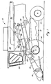
- FIG. 1 shows an agricultural combine 10 with a supporting structure 12 which is in engagement with the Ground wheels 14 is provided.
- the Combine 10 is shown with wheels, he could also be provided with two or four crawlers.
- a cutter 16 is used for harvesting crops and around an inclined conveyor 18th used to feed.
- the feeder 18 contains one Conveying device for the harvested crop of a guide drum 20 supply.
- the guide drum 20 carries the material upwards an inlet transition section 22 and one rotatable, designed for threshing and separating Good processing device 24 too.
- the illustrated Good processing device 24 is axial in the combine arranged, but it could also in other orientations be arranged relative to the longitudinal axis of the combine 10.
- the present invention is based on a Good processing device 24 is described with a rotor, she could also on a combine 10 with a conventional, transversely arranged threshing drum, which with a Threshing basket interacts to be used.
- the crop processing device 24 threshes and separates it harvested crop.
- the grain and chaff fall through grates Bottom of the crop processing device 24 in a cleaning system 26.
- the cleaning system 26 removes the chaff and does that clean grain an elevator (not shown) for clean grain to.
- the elevator for clean grain puts the grain in one Grain tank 28 from.
- the clean grain in the grain tank 28 can by an unloading screw conveyor 30 a truck or trailer be fed.
- Threshed straw, freed from grain, is removed from the Good processing device 24 through an outlet 32 Ejection drum 34 fed.
- the ejection drum 34 pushes it Straw in turn from the rear of the combine 10. It is note that the ejection drum 34 freed the grain It could also be fed directly to a straw chopper.
- the Combine 10 is operated from an operator's cab 35 controlled from.
- the crop processing device 24 comprises a cylindrical one Rotor housing 36 and one arranged in rotor housing 36, rotatable rotor 37.
- the front part of the rotor 37 and the Rotor housings 36 define a loading section 38.
- Downstream of the feed section 38 are a threshing section 39, a separating section 40 and an outlet section 41
- Rotor 37 is in the loading section 38 with a conical Rotor drum provided, the helical loading elements for engaging in good that it from the guide drum 20th and receives from the inlet transition area 22.
- threshing section 39 Immediately downstream of the loading section 38 is the threshing section 39.
- the rotor 37 has a cylindrical one Rotor drum with a number of threshing elements is provided to the goods received from the loading section 38 to thresh.
- the Separation section 40 Downstream of the threshing section 39 is the Separation section 40, in which the threshed good still contained grain is released and by a bottom Rust in the rotor housing 36 into the cleaning system 28 falls.
- the separating section 40 goes into the outlet section 41 above, in which the grain (straw) freed from the Good processing device 24 is ejected.
- the front wheels 14 of the combine 10 are by a hydrostatic transmission 50 driven.
- the hydrostatic Transmission 50 is not in a conventional manner shown internal combustion engine driven.
- the hydrostatic The transmission in turn drives a manual transmission 52.
- Two driving shafts 54 extend from the manual transmission 52 outside and drive final drives 56 of the front wheels 14.
- the hydrostatic transmission 50 includes a pump unit and a Motor unit.
- the pump unit and / or the motor unit are equipped with adjustable swash plates.
- the adjustable Swash plates control the output speed of the transmission 50 and its direction of rotation.
- Electromagnetically controlled Control valves control the positions of the swash plates.
- the steerable rear wheels 14 can also by wheel motors are driven, which are attached directly to the wheels 14. The speed of the wheel motors can be seen through the below throughput control system described can be controlled.
- the inclined conveyor 18 includes Housing 60 with a chain conveyor arranged therein 62.
- the chain conveyor 62 comprises a rear one Drive pinion 64 and a front drum 66 to the one Chain conveyor 68 is arranged.
- the chain conveyor 68 includes at least two longitudinally arranged chains 70, on which transversely extending driver wings 72 are attached.
- the front one Drum 66 is equipped with an axis 74. This front Axis 74 can move freely in the housing 60 to a limited extent slide up and down.
- the front drum 66 is with a Inclined conveyor force sensor 76 equipped with a Line 78 with an electronic control 80 in Communication is there.
- the feeder force sensor 76 of the feeder 18 two Sensor.
- the first sensor includes a potentiometer, which the Position of the front drum 66 relative to the housing 60 measures.
- the upward displacement of the front drum 66 is a measure for that exerted by the crop on the front drum 66 Force since the harvested crop is part of the weight of the Chain conveyor 62 must overcome to drum 66 to raise.
- a second sensor is used to measure the force in the Feeder 18 to measure because the position of the front Then drum 66 no longer changes relative to the housing 62.
- This second sensor is a force sensing element, which over the Axis 74 from the harvested crop to the front drum 66 exerted upward force. That from Inclined conveyor force sensor 76 of the inclined conveyor 18 generated Signal is directly linked to the throughput of the crop, that passes through the feeder 18 and therefore represents the real throughput of the crop that goes into the combine 10 arrives.
- the present invention is based on one use an inclined conveyor 18 with a chain conveyor 62 is described and illustrated, for which it is good suitable, it can also be used on inclined conveyors be the several transversely arranged conveyor drums or lengthways have arranged screw conveyors.
- the key feature of the present invention is a feed force signal to use that of the harvested, passing through the feeder Generated well, and with the throughput in it To connect.
- a feeder with cross arranged conveyor drums could the upward, force acting on the shafts of the conveyor drums is the inclined conveyor force signal provide.
- an inclined conveyor longitudinally arranged screw conveyors could be those of the harvested Force exerted well on the screw conveyor troughs as a measure of serve the feeder signal.
- An electronic controller 80 controls the harvesting speed of the combine 10. This means that the electronic Controller 80 the forward speed (harvesting speed) of the combine 10 by adjusting the position of the Swashplate of the hydrostatic transmission 50 controls by the operation of the electromagnetically operated control valves a line 82 is controlled.
- the controller 80 receives through line 78 receives a feed force signal from Inclined conveyor force sensor 76. The crop throughput is also available Related crop loss rates.
- the controller 80 also receives via a line 88 from a switch 90 Target loss rate signal, the information about a contains the desired loss rate.
- the switch 90 is in the Operator cabin 35 arranged.
- the Controller 80 receives this target loss rate signal and sets it into a desired throughput signal.
- the controller 80 also receives the current throughput from the feeder force sensor 76.
- the controller 80 controls the forward speed of the combine 10 so that the desired force signal is the same the actual force signal of the inclined conveyor force sensor 76 is.
- the Inclined conveyor 18 with a moisture sensor 92 equipped with the controller 80 via a line 94 communicated.
- the moisture sensor 92 senses the moisture in the crop that passes through the feeder 18.
- the Moisture signal can be used to signal over the real throughput or signal over the desired one Change throughput to slow combine 10, when he picks up crop with high humidity.
- the moisture signal can be used, adjust the harvesting speed of the combine 10 directly. If the crop moisture level is higher than one is a fixed amount, the combine 10 by one certain amount slowed down. If the combine 10 for example, picking up weed green crops, the humidity sensor 92 becomes an increased humidity measure up. The moisture signal is on line 94 of the Control 80 are supplied. The one receiving this signal Controller 80 will first determine if the crop moisture is above a fixed amount, and if so, controller 80 becomes combine 10 slow down immediately.
Landscapes
- Life Sciences & Earth Sciences (AREA)
- Environmental Sciences (AREA)
- Harvester Elements (AREA)
- Outside Dividers And Delivering Mechanisms For Harvesters (AREA)
- Combines (AREA)
Applications Claiming Priority (2)
| Application Number | Priority Date | Filing Date | Title |
|---|---|---|---|
| US09/813,264 US6951514B1 (en) | 2001-03-20 | 2001-03-20 | Throughput control for combines using feederhouse signal |
| US813264 | 2001-03-20 |
Publications (3)
| Publication Number | Publication Date |
|---|---|
| EP1266558A2 true EP1266558A2 (fr) | 2002-12-18 |
| EP1266558A3 EP1266558A3 (fr) | 2005-05-11 |
| EP1266558B1 EP1266558B1 (fr) | 2006-12-06 |
Family
ID=25211918
Family Applications (1)
| Application Number | Title | Priority Date | Filing Date |
|---|---|---|---|
| EP02005835A Expired - Lifetime EP1266558B1 (fr) | 2001-03-20 | 2002-03-14 | Convoyeur élévateur muni d'un capteur de force pour détecter le débit d' une moissonneuse-bateuse |
Country Status (8)
| Country | Link |
|---|---|
| US (1) | US6951514B1 (fr) |
| EP (1) | EP1266558B1 (fr) |
| AR (1) | AR035785A1 (fr) |
| AU (1) | AU783967B2 (fr) |
| BR (1) | BRPI0200855B1 (fr) |
| CA (1) | CA2373667C (fr) |
| DE (1) | DE50208879D1 (fr) |
| DK (1) | DK1266558T3 (fr) |
Cited By (6)
| Publication number | Priority date | Publication date | Assignee | Title |
|---|---|---|---|---|
| EP2915422A1 (fr) * | 2014-03-03 | 2015-09-09 | CLAAS Selbstfahrende Erntemaschinen GmbH | Machine agricole |
| EP3398420A1 (fr) | 2017-05-02 | 2018-11-07 | Deere & Company | Procédé et dispositif de contrôle de la vitesse d'une presse à balles |
| EP3527059A1 (fr) * | 2018-02-15 | 2019-08-21 | CLAAS Selbstfahrende Erntemaschinen GmbH | Moissonneuse-batteuse ainsi que son procédé de fonctionnement |
| DE102021107874A1 (de) | 2021-03-29 | 2022-09-29 | Deere & Company | Verfahren und Anordnung zur Messung des Durchsatzes einer Erntemaschine |
| EP4205528A1 (fr) | 2022-01-04 | 2023-07-05 | CNH Industrial Belgium N.V. | Réglage des paramètres de récolte sur un récolteur d'une moissonneuse-batteuse |
| US12575492B2 (en) | 2022-04-20 | 2026-03-17 | Deere & Company | Crop moisture detection in a combine harvester |
Families Citing this family (23)
| Publication number | Priority date | Publication date | Assignee | Title |
|---|---|---|---|---|
| US6834484B2 (en) * | 2001-12-18 | 2004-12-28 | Deere & Company | Automatic control initiation for a harvester |
| DE10253081A1 (de) * | 2002-11-13 | 2004-05-27 | Claas Selbstfahrende Erntemaschinen Gmbh | Verfahren zur Steuerung der Fahrgeschwindigkeit einer Erntemaschine |
| DE102011086021A1 (de) * | 2011-11-09 | 2013-05-16 | Deere & Company | Anordnung und Verfahren zur automatischen Dokumentation von Situationen bei der Feldarbeit |
| US9179600B2 (en) * | 2012-11-27 | 2015-11-10 | Deere & Company | Mower-conditioner header speed control based on forward travel speed |
| US10178828B2 (en) | 2013-02-20 | 2019-01-15 | Deere & Company | Per plant crop sensing resolution |
| US9668420B2 (en) | 2013-02-20 | 2017-06-06 | Deere & Company | Crop sensing display |
| US9282693B2 (en) | 2013-02-20 | 2016-03-15 | Deere & Company | Data encoding with planting attributes |
| US11212962B2 (en) | 2013-02-20 | 2022-01-04 | Deere & Company | Field condition determination |
| US9693503B2 (en) | 2013-02-20 | 2017-07-04 | Deere & Company | Crop sensing |
| US9066465B2 (en) | 2013-02-20 | 2015-06-30 | Deere & Company | Soil compaction reduction system and method |
| US8973342B2 (en) * | 2013-03-08 | 2015-03-10 | Deere & Company | Load control system and method for an agricultural harvester |
| US9372109B2 (en) * | 2013-03-15 | 2016-06-21 | Raven Industires, Inc. | Harvester elevator in-flow weight sensor and methods for the same |
| US9410840B2 (en) | 2013-03-15 | 2016-08-09 | Raven Industries, Inc. | Multi-variable yield monitor and methods for the same |
| US9310329B2 (en) * | 2013-03-15 | 2016-04-12 | Raven Industries, Inc. | Remote moisture sensor and methods for the same |
| WO2015160837A2 (fr) * | 2014-04-15 | 2015-10-22 | Raven Industries, Inc. | Système de surveillance de rendement basé sur un moissonnage et procédé associé |
| US10440886B2 (en) * | 2017-09-27 | 2019-10-15 | Deere & Company | Feedrate control with slip compensation |
| US10820504B2 (en) | 2018-07-03 | 2020-11-03 | Cnh Industrial America Llc | System and method for determining the residue yield of plant materials harvested by an agricultural harvester |
| DE102018212075A1 (de) * | 2018-07-19 | 2020-01-23 | Deere & Company | Mähdrescher mit einem Schrägförderer mit aktorisch verstellbarer, unterer Umlenkwalze |
| US11944034B2 (en) | 2019-11-15 | 2024-04-02 | Cnh Industrial America Llc | Agricultural harvester with proactive response to moisture level of collected crop material |
| US11533844B2 (en) | 2020-01-31 | 2022-12-27 | Cnh Industrial America Llc | Load based ground speed control method |
| EP4088559B1 (fr) * | 2021-05-10 | 2026-01-28 | AGCO International GmbH | Détection de perte de grain |
| EP4256939B1 (fr) * | 2022-04-05 | 2024-10-23 | SMF - Holding GmbH | Engin d'abattage-façonnage permettant de traiter les produits de la récolte et procédés de détermination des propriétés des produits de la récolte |
| US20240122114A1 (en) * | 2022-10-14 | 2024-04-18 | Cnh Industrial America Llc | Header automation system utilizing front feeder drum position variation over time |
Family Cites Families (27)
| Publication number | Priority date | Publication date | Assignee | Title |
|---|---|---|---|---|
| US3073099A (en) | 1959-03-04 | 1963-01-15 | Massey Ferguson Ltd | Combine control system |
| US3093946A (en) | 1959-10-08 | 1963-06-18 | Pitt Arnold | Load responsive control for power systems |
| US3138908A (en) | 1960-09-01 | 1964-06-30 | Budzich Tadeusz | Control in harvesting machinery |
| DE1265476B (de) * | 1965-03-03 | 1968-04-04 | Franz Wienecke Dr Ing | Selbsttaetige Regeleinrichtung fuer Maehdrescher |
| US3514929A (en) | 1967-08-21 | 1970-06-02 | Deere & Co | Control system for a harvesting machine |
| US3481122A (en) | 1967-10-23 | 1969-12-02 | Int Harvester Co | Ground speed control |
| GB1280464A (en) * | 1968-10-04 | 1972-07-05 | Ransomes Sims & Jefferies Ltd | Improvements in or relating to combine harvesters |
| GB1286256A (en) * | 1968-10-11 | 1972-08-23 | Massey Ferguson Gmbh | Improvements in or relating to mobile agricultural crop-collecting and crop-treating machines |
| US3546860A (en) | 1969-03-27 | 1970-12-15 | Int Harvester Co | Automatic forward travel control |
| ZA737351B (en) * | 1972-10-05 | 1974-08-28 | Lucas Electrical Co Ltd | Harvesting machines |
| US4138837A (en) * | 1976-10-26 | 1979-02-13 | Deere & Company | Variable speed reversible drive for a harvesting apparatus |
| US4130980A (en) * | 1977-01-06 | 1978-12-26 | International Harvester Company | Combine automatic travel control system |
| US4487002A (en) | 1981-07-17 | 1984-12-11 | Gary W. Krutz | Automatic ground speed controller |
| US4458471A (en) | 1981-12-31 | 1984-07-10 | Allis-Chalmers Corp. | Combine speed control |
| US4430847A (en) * | 1982-07-23 | 1984-02-14 | Allis-Chalmers Corporation | Combine feed reverser |
| GB2186777B (en) | 1986-02-20 | 1989-11-22 | Massey Ferguson Services Nv | Ground speed control |
| US4893249A (en) * | 1987-12-17 | 1990-01-09 | Pitney Bowes, Inc. | Mailing machine |
| GB8814936D0 (en) | 1988-06-23 | 1988-07-27 | Ford New Holland Nv | Combine ground speed control system |
| US4967544A (en) * | 1989-01-05 | 1990-11-06 | Deere & Company | Automatic speed control system for a harvesting assembly |
| JP3081928B2 (ja) | 1991-07-12 | 2000-08-28 | ヤンマー農機株式会社 | 収穫機 |
| DE4311054C2 (de) | 1993-04-03 | 2002-12-05 | Claas Kgaa Mbh | Selbstfahrende landwirtschaftliche Erntemaschine |
| EP0777960A3 (fr) | 1993-06-28 | 1999-05-12 | New Holland Belgium N.V. | Procédé de commande pour moissonneuses autopropulsées |
| US5855108A (en) | 1996-02-16 | 1999-01-05 | Case Corporation | Alarm monitor for belt slip in a combine |
| US6036597A (en) | 1998-02-11 | 2000-03-14 | Agco Corporation | Combine harvester rotor load control |
| GB9811177D0 (en) | 1998-05-26 | 1998-07-22 | Ford New Holland Nv | Methods for generating field maps |
| DE19903471C1 (de) * | 1999-01-29 | 2000-06-08 | Deere & Co | Erntemaschine mit Durchsatzmeßvorrichtung |
| US6213870B1 (en) * | 1999-03-24 | 2001-04-10 | Caterpillar Inc. | Stall prevention system |
-
2001
- 2001-03-20 US US09/813,264 patent/US6951514B1/en not_active Expired - Lifetime
-
2002
- 2002-02-27 CA CA002373667A patent/CA2373667C/fr not_active Expired - Fee Related
- 2002-03-14 DK DK02005835T patent/DK1266558T3/da active
- 2002-03-14 DE DE50208879T patent/DE50208879D1/de not_active Expired - Lifetime
- 2002-03-14 AU AU26139/02A patent/AU783967B2/en not_active Ceased
- 2002-03-14 EP EP02005835A patent/EP1266558B1/fr not_active Expired - Lifetime
- 2002-03-19 BR BRPI0200855-6A patent/BRPI0200855B1/pt not_active IP Right Cessation
- 2002-03-20 AR ARP020101000A patent/AR035785A1/es active IP Right Grant
Cited By (10)
| Publication number | Priority date | Publication date | Assignee | Title |
|---|---|---|---|---|
| EP2915422A1 (fr) * | 2014-03-03 | 2015-09-09 | CLAAS Selbstfahrende Erntemaschinen GmbH | Machine agricole |
| RU2676959C2 (ru) * | 2014-03-03 | 2019-01-11 | КЛААС Зельбстфаренде Эрнтемашинен ГмбХ | Сельскохозяйственная рабочая машина |
| EP3398420A1 (fr) | 2017-05-02 | 2018-11-07 | Deere & Company | Procédé et dispositif de contrôle de la vitesse d'une presse à balles |
| US10694670B2 (en) | 2017-05-02 | 2020-06-30 | Deere & Company | Method and arrangement for control of the speed of a baler |
| EP3527059A1 (fr) * | 2018-02-15 | 2019-08-21 | CLAAS Selbstfahrende Erntemaschinen GmbH | Moissonneuse-batteuse ainsi que son procédé de fonctionnement |
| US11083135B2 (en) | 2018-02-15 | 2021-08-10 | Claas Selbstfahrende Erntemaschinen Gmbh | Combine harvester and method for the operation thereof |
| DE102021107874A1 (de) | 2021-03-29 | 2022-09-29 | Deere & Company | Verfahren und Anordnung zur Messung des Durchsatzes einer Erntemaschine |
| US12582040B2 (en) | 2021-03-29 | 2026-03-24 | Deere & Company | Method and apparatus for measuring crop throughput |
| EP4205528A1 (fr) | 2022-01-04 | 2023-07-05 | CNH Industrial Belgium N.V. | Réglage des paramètres de récolte sur un récolteur d'une moissonneuse-batteuse |
| US12575492B2 (en) | 2022-04-20 | 2026-03-17 | Deere & Company | Crop moisture detection in a combine harvester |
Also Published As
| Publication number | Publication date |
|---|---|
| DK1266558T3 (da) | 2007-04-10 |
| AU2613902A (en) | 2002-09-26 |
| AR035785A1 (es) | 2004-07-14 |
| DE50208879D1 (de) | 2007-01-18 |
| BRPI0200855B1 (pt) | 2015-03-17 |
| BR0200855A (pt) | 2003-03-25 |
| AU783967B2 (en) | 2006-01-05 |
| CA2373667C (fr) | 2006-02-14 |
| EP1266558B1 (fr) | 2006-12-06 |
| CA2373667A1 (fr) | 2002-09-20 |
| US6951514B1 (en) | 2005-10-04 |
| EP1266558A3 (fr) | 2005-05-11 |
Similar Documents
| Publication | Publication Date | Title |
|---|---|---|
| EP1266558B1 (fr) | Convoyeur élévateur muni d'un capteur de force pour détecter le débit d' une moissonneuse-bateuse | |
| EP1243173B1 (fr) | Convoyeur élévateur muni d'un capteur de force pour détecter le débit d'une moissonneuse-batteuse | |
| EP3662741B1 (fr) | Machine de travail agricole ainsi que procédé de fonctionnement d'une machine de travail agricole | |
| DE102008017671B4 (de) | Messanordnung zur Massendurchsatzerfassung mit Massen- und Volumenmessung und darauf basierender Massendichtenbestimmung sowie Massendurchsatzangabe bei kleinen Durchsätzen anhand der zuletzt erfassten Massendichte | |
| EP1256270B1 (fr) | Arrangement pour le ramassage de la récolte | |
| EP1297734B1 (fr) | Machine de récolte avec une vitesse d'avance qui est dépendante de l'inclinaison | |
| EP2803256B1 (fr) | Moissonneuse dotée d'un réglage de la vitesse de propulsion anticipé | |
| EP3597027B1 (fr) | Moissonneuse-batteuse doté d'un convoyeur incliné pourvu de rouleau de déviation inférieur réglable | |
| EP2681984B1 (fr) | Moissonneuse-batteuse | |
| EP1321025B1 (fr) | Machine de récolte avec dispositif de détection de végétaux | |
| EP1344444B1 (fr) | Dispositif de détection de la présence de flux de produits dans une moissonneuse | |
| EP2845461B1 (fr) | Agencement de mesure de perte dans une moissonneuse-batteuse | |
| EP1287732B1 (fr) | Tête de récolte | |
| EP1281310A1 (fr) | Machine de récolte avec contrôle de la vitesse | |
| EP2957164B1 (fr) | Assemblage de convoyeur-élévateur pour une moissonneuse-batteuse | |
| EP2345320A1 (fr) | Récolteuse automobile | |
| EP1232682B1 (fr) | Moissonneuse-batteuse avec puissance motrice dépendante du tablier de coupe | |
| EP1731983A1 (fr) | Machine de travail agricole pourvue d'un dispositif de déversement et d'un capteur de collision | |
| DE102014219049B4 (de) | Feldhäcksler mit reversierbarer Konditioniereinrichtung | |
| EP2248411B1 (fr) | Moissonneuse | |
| EP1046333A1 (fr) | Machine de récolte | |
| EP2761984A1 (fr) | Capteur d'oscillations | |
| EP3391725A1 (fr) | Ensemble à convoyeur à vis pour une moissonneuse-batteuse | |
| EP1790210B1 (fr) | Dispositif d'alimentation pour une faucheuse-hâcheuse | |
| EP1243174A1 (fr) | Moissonneuse-batteuse avec capteur d'humidité |
Legal Events
| Date | Code | Title | Description |
|---|---|---|---|
| PUAI | Public reference made under article 153(3) epc to a published international application that has entered the european phase |
Free format text: ORIGINAL CODE: 0009012 |
|
| AK | Designated contracting states |
Kind code of ref document: A2 Designated state(s): AT BE CH CY DE DK ES FI FR GB GR IE IT LI LU MC NL PT SE TR |
|
| AX | Request for extension of the european patent |
Free format text: AL;LT;LV;MK;RO;SI |
|
| PUAL | Search report despatched |
Free format text: ORIGINAL CODE: 0009013 |
|
| AK | Designated contracting states |
Kind code of ref document: A3 Designated state(s): AT BE CH CY DE DK ES FI FR GB GR IE IT LI LU MC NL PT SE TR |
|
| AX | Request for extension of the european patent |
Extension state: AL LT LV MK RO SI |
|
| RIC1 | Information provided on ipc code assigned before grant |
Ipc: 7A 01D 41/127 B Ipc: 7A 01D 41/12 A |
|
| 17P | Request for examination filed |
Effective date: 20051111 |
|
| AKX | Designation fees paid |
Designated state(s): BE DE DK FR GB IT |
|
| GRAP | Despatch of communication of intention to grant a patent |
Free format text: ORIGINAL CODE: EPIDOSNIGR1 |
|
| GRAS | Grant fee paid |
Free format text: ORIGINAL CODE: EPIDOSNIGR3 |
|
| GRAA | (expected) grant |
Free format text: ORIGINAL CODE: 0009210 |
|
| AK | Designated contracting states |
Kind code of ref document: B1 Designated state(s): BE DE DK FR GB IT |
|
| REG | Reference to a national code |
Ref country code: GB Ref legal event code: FG4D Free format text: NOT ENGLISH |
|
| REF | Corresponds to: |
Ref document number: 50208879 Country of ref document: DE Date of ref document: 20070118 Kind code of ref document: P |
|
| GBT | Gb: translation of ep patent filed (gb section 77(6)(a)/1977) |
Effective date: 20070131 |
|
| REG | Reference to a national code |
Ref country code: DK Ref legal event code: T3 |
|
| ET | Fr: translation filed | ||
| PLBE | No opposition filed within time limit |
Free format text: ORIGINAL CODE: 0009261 |
|
| STAA | Information on the status of an ep patent application or granted ep patent |
Free format text: STATUS: NO OPPOSITION FILED WITHIN TIME LIMIT |
|
| 26N | No opposition filed |
Effective date: 20070907 |
|
| PGFP | Annual fee paid to national office [announced via postgrant information from national office to epo] |
Ref country code: FR Payment date: 20140317 Year of fee payment: 13 Ref country code: IT Payment date: 20140321 Year of fee payment: 13 |
|
| PGFP | Annual fee paid to national office [announced via postgrant information from national office to epo] |
Ref country code: GB Payment date: 20140327 Year of fee payment: 13 |
|
| GBPC | Gb: european patent ceased through non-payment of renewal fee |
Effective date: 20150314 |
|
| PG25 | Lapsed in a contracting state [announced via postgrant information from national office to epo] |
Ref country code: IT Free format text: LAPSE BECAUSE OF NON-PAYMENT OF DUE FEES Effective date: 20150314 |
|
| REG | Reference to a national code |
Ref country code: FR Ref legal event code: ST Effective date: 20151130 |
|
| PG25 | Lapsed in a contracting state [announced via postgrant information from national office to epo] |
Ref country code: GB Free format text: LAPSE BECAUSE OF NON-PAYMENT OF DUE FEES Effective date: 20150314 |
|
| PG25 | Lapsed in a contracting state [announced via postgrant information from national office to epo] |
Ref country code: FR Free format text: LAPSE BECAUSE OF NON-PAYMENT OF DUE FEES Effective date: 20150331 |
|
| PGFP | Annual fee paid to national office [announced via postgrant information from national office to epo] |
Ref country code: BE Payment date: 20190327 Year of fee payment: 18 Ref country code: DK Payment date: 20190327 Year of fee payment: 18 |
|
| REG | Reference to a national code |
Ref country code: DK Ref legal event code: EBP Effective date: 20200331 |
|
| REG | Reference to a national code |
Ref country code: BE Ref legal event code: MM Effective date: 20200331 |
|
| PG25 | Lapsed in a contracting state [announced via postgrant information from national office to epo] |
Ref country code: BE Free format text: LAPSE BECAUSE OF NON-PAYMENT OF DUE FEES Effective date: 20200331 |
|
| PG25 | Lapsed in a contracting state [announced via postgrant information from national office to epo] |
Ref country code: DK Free format text: LAPSE BECAUSE OF NON-PAYMENT OF DUE FEES Effective date: 20200331 |
|
| PGFP | Annual fee paid to national office [announced via postgrant information from national office to epo] |
Ref country code: DE Payment date: 20210219 Year of fee payment: 20 |
|
| REG | Reference to a national code |
Ref country code: DE Ref legal event code: R071 Ref document number: 50208879 Country of ref document: DE |