EP2915422A1 - Machine agricole - Google Patents
Machine agricole Download PDFInfo
- Publication number
- EP2915422A1 EP2915422A1 EP14196705.9A EP14196705A EP2915422A1 EP 2915422 A1 EP2915422 A1 EP 2915422A1 EP 14196705 A EP14196705 A EP 14196705A EP 2915422 A1 EP2915422 A1 EP 2915422A1
- Authority
- EP
- European Patent Office
- Prior art keywords
- flow rate
- moisture
- gutfeuchtesignal
- crop
- machine according
- Prior art date
- Legal status (The legal status is an assumption and is not a legal conclusion. Google has not performed a legal analysis and makes no representation as to the accuracy of the status listed.)
- Granted
Links
Images


Classifications
-
- A—HUMAN NECESSITIES
- A01—AGRICULTURE; FORESTRY; ANIMAL HUSBANDRY; HUNTING; TRAPPING; FISHING
- A01D—HARVESTING; MOWING
- A01D41/00—Combines, i.e. harvesters or mowers combined with threshing devices
- A01D41/12—Details of combines
- A01D41/127—Control or measuring arrangements specially adapted for combines
- A01D41/1277—Control or measuring arrangements specially adapted for combines for measuring grain quality
-
- A—HUMAN NECESSITIES
- A01—AGRICULTURE; FORESTRY; ANIMAL HUSBANDRY; HUNTING; TRAPPING; FISHING
- A01D—HARVESTING; MOWING
- A01D41/00—Combines, i.e. harvesters or mowers combined with threshing devices
- A01D41/12—Details of combines
- A01D41/127—Control or measuring arrangements specially adapted for combines
- A01D41/1271—Control or measuring arrangements specially adapted for combines for measuring crop flow
-
- A—HUMAN NECESSITIES
- A01—AGRICULTURE; FORESTRY; ANIMAL HUSBANDRY; HUNTING; TRAPPING; FISHING
- A01D—HARVESTING; MOWING
- A01D57/00—Delivering mechanisms for harvesters or mowers
- A01D57/20—Delivering mechanisms for harvesters or mowers with conveyor belts
-
- A—HUMAN NECESSITIES
- A01—AGRICULTURE; FORESTRY; ANIMAL HUSBANDRY; HUNTING; TRAPPING; FISHING
- A01F—PROCESSING OF HARVESTED PRODUCE; HAY OR STRAW PRESSES; DEVICES FOR STORING AGRICULTURAL OR HORTICULTURAL PRODUCE
- A01F12/00—Parts or details of threshing apparatus
- A01F12/18—Threshing devices
-
- A—HUMAN NECESSITIES
- A01—AGRICULTURE; FORESTRY; ANIMAL HUSBANDRY; HUNTING; TRAPPING; FISHING
- A01F—PROCESSING OF HARVESTED PRODUCE; HAY OR STRAW PRESSES; DEVICES FOR STORING AGRICULTURAL OR HORTICULTURAL PRODUCE
- A01F12/00—Parts or details of threshing apparatus
- A01F12/58—Control devices; Brakes; Bearings
Definitions
- the present invention relates to an agricultural work machine according to the preamble of claim 1.
- Agricultural work machines which include in particular self-propelled harvesters such as combine harvesters, regularly have various implements that can be operated when processing crop with changing parameters.
- the setting of these parameters is also referred to as machine parameter setting.
- machine parameter setting For optimal operation it is recommended to set the machine parameter setting depending on various boundary conditions, including in particular the type, quantity and condition of the stock in the field or the crop.
- a disadvantage of this prior art is that especially in a design of the moisture sensor as a capacitive sensor, the measurement of moisture can be inaccurate. This is because such a sensor essentially measures and determines the total amount of water passed by it. However, this total amount of water is not only dependent on the relative humidity of the crop, but also on the absolute amount of crop at the time of measurement. Consequently, the measured moisture is often falsified upward at a higher throughput of the crop and, accordingly, at a low flow rate, if necessary down.
- the object of the invention is to develop an agricultural machine so that a more accurate determination of moisture in the crop is more accurate.
- Essential for the invention is the recognition that in such an agricultural machine often also the currently recorded throughput of the crop is sensory detected.
- a layer height sensor is usually provided, which determines the current throughput of recorded crop in the region of a feeder and especially on the feederhouse.
- this determination of the current flow rate can be used to correct the measurement of the moisture of the recorded crop accordingly.
- the corrupting influence of the received flow rate on the measured humidity as described above can be corrected so that a more accurate value of the humidity is available for the machine parameter setting.
- the relationship between the determined flow rate and an adaptation of the measured humidity may be indicated by a function described by the preferred embodiment of subclaim 3.
- the proposed solution also makes it possible to take account of the phenomenon that below a certain throughput of crop, the detection of moisture becomes very inaccurate. Therefore, the dependent claim 4 proposes in so To maintain a case the last determined, corrected moisture value until a more accurate measurement is possible by an increase of the recorded crop again.
- the subclaims 10 to 13 describe how the measured moisture of the crop could advantageously influence the control of the implements of the working machine.
- the dependent claim 14 takes into account the fact that the measured moisture of the crop can also be used to optimize an overload protection function of the threshing unit of a combine harvester.
- claim 15 relates to a further processing of the measured moisture of the crop, which can be used even beyond the agricultural machine itself, namely by the measured moisture of the crop is linked to the respective position at which this moisture of the crop was measured, so that the distribution the moisture of the crop can be geographically mapped to the stock field. This information is very important from an economic point of view and then allows for improved agricultural use of the existing field.
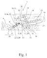
- the in the Fig. 1 illustrated proposed agricultural work machine which is here for example a combine harvester 1, is arranged for processing crops and includes a feed assembly 2 for receiving the crop, a moisture sensor assembly 3 for measuring a moisture of the recorded crop and for generating a measured on the Moisture based Gutfeuchtesignals and a flow rate sensor assembly 4, which is preferably a layer height sensor assembly 4a, for determining a flow rate of the picked crop.
- the proposed agricultural work machine is now characterized in that the Gutfeuchtesignal is post-corrected based on the specific flow rate.
- Post-correction in this sense may include any adjustment of the good-moisture signal, which depends on the determined flow rate. This adjustment can be done either by a percentage adjustment, such as by a multiplication, by the addition or subtraction of a shift value or by assigning a fixed value to the Gutfeuchtesignal.
- This post-correction can only apply to a certain range of values of either the measured humidity or the specific flow rate and thus fall outside one of these ranges. It is therefore not necessary that the Gutfeuchtesignal is changed at any time under all conditions by the post-correction, which below explanatory examples follow.
- the post-correction of the Gutfeuchtesignals may include both the replacement of the previous Gutfeuchtesignals and the generation of a new, based on the original Gutfeuchtesignal Gutfeuchtesignals, which takes into account the post-correction.
- the feeder assembly may be a header assembly 5 which, as in FIGS Fig. 1 illustrated a reel 6, cutter bar 7 and a auger 8 includes.
- the header assembly further includes also a feeder 9.
- the reel 6, the cutter bar 7 and the auger 8 can be summarized here referred to as a cutting unit 10, so that the cut from the cutting unit 10 and retracted crop as Erntegutstrom from the feeder 9 for further processing in the combine harvester 1 is promoted.
- the crop is received by the intake assembly 2.
- the picked crop reaches the threshing 11, which comprises the threshing cylinder 12 and the concave 13.
- Conveying downstream of the threshing unit 2 is a deflection drum 14, via which the crop stream passes into the separating device 15 for separating free mobile grains. This is followed by a cleaning device 16 with one or more screen levels 17 and a fan 18. Further downstream are also as in the Fig. 1 shown, a grain elevator 19 and a grain tank 20th
- the Gutfeuchtesignal is generated substantially continuously. This means that the Gutfeuchtesignal is generated either continuously or at least with a small time interval between the detection times. Alternatively or additionally, the current generation also applies to the throughput quantity. Thus, the Gutfeuchtesignal can be generated online and thus virtually in real time and the throughput can also be determined virtually in real time. From both together, it is preferred that the Gutfeuchtesignal nachkorrigiert substantially ongoing based on the specific flow rate becomes. Thus, the post-corrected Gutfeuchtesignal is always up to date.
- the good-moisture signal is post-corrected on the basis of the determined throughput quantity by means of a throughput correction function.
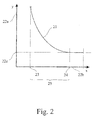
- a throughput correction function may also be performed by a correction curve as described in US Pat Fig. 2 is presented, be given.
- a correction factor 21 by which the crop moisture signal is multiplied is read in accordance with the value along the y-axis 22a and determined as a function of the flow rate which is plotted on the x-axis 22b.
- a correction factor greater than one is applied, which becomes smaller as the flow rate increases.
- the crop type of harvested crop also influences the measured moisture.
- the Gutfeuchtesignal is also nachkorrigiert based on a Fruchtartbetician. This crop determination may be based on detection of the crop by sensors or on a corresponding operator input.
- the good moisture signal is corrected to a value of the good moisture signal before the minimum flow rate is not reached.
- This connection is also from the Fig. 2 to recognize, at the below the minimum throughput 23, no change in the good moisture signal through the throughput correction function occurs more. Rather, the last determined value of the Gutfeuchtesignals - taking into account the post-correction - maintained. Therefore, it is further preferred that in such a case the Gutfeuchtesignal is held on the value of the Gutfeuchtesignals before falling below the minimum flow rate.
- the Gutfeuchtesignal remains substantially unchanged by the post-correction.
- the flow rate correction function has a constant value of one in this range, corresponding to the unit value 22c.
- the minimum throughput 23 and the maximum throughput 24 results as well as in the Fig. 2 illustrates a correction range 25 between these two values.
- the Gutfeuchtesignal is nachkorrigiert so that measured by the moisture sensor assembly 3 moisture of the recorded crop, which may be in particular an absolute humidity of the recorded crop, a total of the specific flow rate is obtained. In this way, a post-corrected Gutfeuchtesignal is obtained, which indicates a percentage of moisture.
- the correction range 25 lies between the maximum throughput 24 and the minimum throughput 23.
- the moisture sensor arrangement 3 and, alternatively or additionally, the layer height sensor arrangement 4a is arranged on the intake arrangement 2 and in particular in a feed channel of the intake arrangement 2.
- Fig. 3 shown which is a plan view of the inclined conveyor 9 of the combine 1 of the Fig. 1 reproduces.
- a layer height roller 28 allows the determination of the flow rate through the above-mentioned layer height sensor assembly 4a, the component of which forms.
- the intake channel is thus formed essentially in this section by the upper side of the inclined conveyor 9 shown.
- the humidity sensor assembly 3 is arranged.
- the moisture sensor arrangement 3 is set up for non-contact measurement of the moisture of the picked crop.
- the humidity sensor arrangement 3 may comprise a capacitive sensor 3a.
- Other possible types of sensors for this moisture sensor arrangement 3, which also operate without contact, are near-infrared sensors, in which case in particular constructions with simple photodiodes and two or three transmitting diodes with fixed wavelengths are suitable.
- the agricultural working machine comprises working devices 29, which include in particular one or more of the group comprising the threshing unit 11, the attachment arrangement 5, the separating device 15 and the cleaning device 16.
- the agricultural work machine also comprises a control arrangement 30 for controlling the work tools 29, wherein it is provided here that the control arrangement 30 activates the work tools 29 based on the good moisture signal.
- the control arrangement 30 activates the work tools 29 based on the good moisture signal.
- This can serve in particular to optimize the Ausdruschgüte or the current diesel consumption.
- the activation of the working devices 29 can preferably take place in such a way that the control arrangement 31 controls the working devices 30 based on the good moisture signal.
- control arrangement 30 may also, according to the embodiment of the Fig. 1 to be an electronic central unit 31, the z. B. also provides an electronic user interface for a user.
- the control arrangement 30 has machine setting machines, which are each assigned to a working device 29 for controlling the working device, and that the control arrangement 31 determines operating parameters of the machine setting machines based on the post-corrected good moisture signal.
- These machine setting machines can be realized in the form of software, so z. B. all these Maschineneinstellautomaten within a corresponding control software within the control assembly 30, here so the electronic central processing unit 31, run. Some or all of these Machine setting machines can also be formed by a separate device.
- control arrangement 30 executes a control activity for controlling a work implement 29 based on a change in the good moisture signal.
- z. B. certain routines for controlling a working device 29 is activated when defined conditions of the Gutfeuchtesignals occur.
- the control arrangement 30 triggers an ascending activity for controlling a working device 29 when the crop moisture signal rises and, in particular, when an upper limit value is exceeded.
- the control arrangement 30 triggers a sinking activity for controlling a working device 29 when the crop moisture signal drops, in particular when it falls below a lower limit.
- control arrangement 30 triggers a variance activity for controlling a work implement 29 when a change limit value is exceeded by a rate of change of the good-moisture signal.
- the triggering of such a variance activity can also be dependent on the rate of change of the Gutfeuchtesignals going in a particular direction.
- the increase, decrease or variance activity can also affect several implements 29.
- Different working devices 29 can also be assigned different upper or lower limit values as well as change limit values, in which case a respective increase, decrease or variance activity can be configured differently depending on the relevant implement 29.
- a first checking step 33 is first carried out to the above upper limit value, in the case of which it has been exceeded, a first triggering step 34 follows the ascending activity. If the upper Limit was not exceeded, the falling below the lower limit value is checked in a second test step 35, after which in the case of falling below in the second triggering step 36, the triggering of Absinkdontician can follow. If this is also not the case, a determination is made in the last test step 37 as to whether the change limit value has been exceeded by a rate of change of the good moisture signal. If this is the case, the variance activity in the third triggering step 38. In this case, even further, in particular subsequent examination and corresponding triggering steps are conceivable.
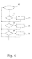
- Fig. 5 a flowchart of the post-correction of the Gutfeuchtesignals in the combine of the Fig. 1 .
- the moisture of the picked crop is measured by the moisture sensor assembly 3 and based on this, the crop moisture signal is generated.
- the subsequent temperature adjustment step 40 provides an adjustment of the Gutfeuchtesignals based on a measured ambient temperature.
- the crop moisture signal is post-corrected based on a crop determination.
- the selection of the correction curve can be based on the particular crop.
- the Gutfeuchtesignal in this way if necessary, but not yet subjected to a post-correction according to the proposal is maintained as a raw signal 42 on the one hand.
- the Gutfeuchtesignal is also subjected to the Nachkorrekturuze 43 a post-correction based on the specific flow rate, such. B. above based on the Fig. 2 has been explained, whereby the layer height related standard signal 44 is obtained.
- this post-correction is dependent on the determined throughput quantity of the good moisture signal, so that the measured layer height is received by the layer height sensor arrangement 4a and the flow rate is determined from it in determining the throughput quantity at the same time as the good moisture determination step 39 in the layer height measurement step 45.
- the lower limit check step 46 which follows the post-correction step 43, it is determined whether the determined flow rate is below the minimum flow rate 23, if so in the maintenance step 47, before the last valid Good Humidity signal - the standard signal 44 after the post-correction Falling below the minimum throughput 23 is treated as currently valid Gutfeuchtesignal.
- the upper limit check step 48 If there is no shortfall of the minimum throughput, it is checked in the upper limit check step 48 whether instead the maximum throughput has been exceeded by the specified throughput. If so, the raw signal 43 is taken as a valid Gutfeuchtesignal in the raw processing step 49, because here the post-correction - as already stated - is not required or would lead to a raw signal 43 identical value. If, on the other hand, the maximum throughput is not exceeded, the determined throughput quantity is in the correction range and the post-corrected standard signal 44 is used further in the correction processing step 50 as a valid good-moisture signal, e.g. B. for the above-described determination of operating parameters of Maschineneinstellautomaten.
- the control arrangement 31 provides an overload protection when controlling the working devices 30, in particular of the threshing unit 11, wherein the control arrangement 30, when an overload is detected, actuates the working devices 29 in accordance with an overload protection routine.
- a sensitivity threshold for determining the overload based on the Gutfeuchtesignal This can be realized in particular in that the agricultural work machine has a drive 51 and a clutch 52 for operating the threshing unit 11 and that a slip threshold of the clutch 52 for detecting the overload based on the Gutfeuchtesignal.
- an overload is detected when the slip of the clutch 52, which may in particular be a belt clutch, exceeds the slip threshold.
- the slip threshold As slip thresholds optionally 8%, 13% and 18% slip can be provided, the currently valid slip threshold is selected depending on the Gutfeuchtesignal.
- control arrangement 31 is submitted to log the Gutfeuchtesignal for mapping, preferably the control arrangement 31 is also set up to set the good moisture signal with position data of the agricultural working machine during the picking up of the crop and, in particular, to transmit the logged good moisture signal with the related position data of the agricultural working machine to a remote processing unit.
- This transmission can in particular via a radio interface, for.
- GSM Global System for Mobile communications
Landscapes
- Life Sciences & Earth Sciences (AREA)
- Environmental Sciences (AREA)
- Combines (AREA)
- Management, Administration, Business Operations System, And Electronic Commerce (AREA)
- Threshing Machine Elements (AREA)
- Harvester Elements (AREA)
Applications Claiming Priority (1)
| Application Number | Priority Date | Filing Date | Title |
|---|---|---|---|
| DE102014102789.2A DE102014102789A1 (de) | 2014-03-03 | 2014-03-03 | Landwirtschaftliche Arbeitsmaschine |
Publications (3)
| Publication Number | Publication Date |
|---|---|
| EP2915422A1 true EP2915422A1 (fr) | 2015-09-09 |
| EP2915422B1 EP2915422B1 (fr) | 2018-11-14 |
| EP2915422B2 EP2915422B2 (fr) | 2022-11-30 |
Family
ID=52021020
Family Applications (1)
| Application Number | Title | Priority Date | Filing Date |
|---|---|---|---|
| EP14196705.9A Active EP2915422B2 (fr) | 2014-03-03 | 2014-12-08 | Machine agricole |
Country Status (5)
| Country | Link |
|---|---|
| US (1) | US9795082B2 (fr) |
| EP (1) | EP2915422B2 (fr) |
| DE (1) | DE102014102789A1 (fr) |
| RU (1) | RU2676959C2 (fr) |
| UA (1) | UA119741C2 (fr) |
Cited By (2)
| Publication number | Priority date | Publication date | Assignee | Title |
|---|---|---|---|---|
| EP3459337A1 (fr) * | 2017-09-15 | 2019-03-27 | CLAAS Selbstfahrende Erntemaschinen GmbH | Engin agricole |
| WO2023194202A1 (fr) * | 2022-04-05 | 2023-10-12 | Smf-Holding Gmbh | Procédé de surveillance d'un flux de récolte, et moissonneuse |
Families Citing this family (17)
| Publication number | Priority date | Publication date | Assignee | Title |
|---|---|---|---|---|
| US10034423B2 (en) * | 2014-07-29 | 2018-07-31 | Deere & Company | Biomass sensing |
| US10834872B2 (en) * | 2015-07-02 | 2020-11-17 | Cnh Industriall America Llc | Unload spout inclination limit adjust system and method |
| JP6675843B2 (ja) * | 2015-09-02 | 2020-04-08 | 株式会社クボタ | コンバイン |
| US9706709B2 (en) * | 2015-09-10 | 2017-07-18 | Deere & Company | Harvester fan speed control based on yield |
| JP6670165B2 (ja) * | 2016-05-09 | 2020-03-18 | ヤンマー株式会社 | 収穫機 |
| DE102017110554A1 (de) | 2017-05-16 | 2018-11-22 | Claas Selbstfahrende Erntemaschinen Gmbh | Mähdrescher |
| DE102018103373A1 (de) * | 2018-02-15 | 2019-08-22 | Claas Selbstfahrende Erntemaschinen Gmbh | Mähdrescher sowie Verfahren zu dessen Betrieb |
| DE102018212075A1 (de) * | 2018-07-19 | 2020-01-23 | Deere & Company | Mähdrescher mit einem Schrägförderer mit aktorisch verstellbarer, unterer Umlenkwalze |
| DE102019125500A1 (de) | 2019-09-23 | 2021-03-25 | Claas Selbstfahrende Erntemaschinen Gmbh | Reinigungseinrichtung an einem Mähdrescher |
| US11944034B2 (en) | 2019-11-15 | 2024-04-02 | Cnh Industrial America Llc | Agricultural harvester with proactive response to moisture level of collected crop material |
| EP3845050B1 (fr) * | 2019-12-30 | 2023-11-29 | AGCO Corporation | Procédés et systèmes de mesure de données de débit de matières organiques de cultures récoltées |
| DE102020117071A1 (de) * | 2020-06-29 | 2021-12-30 | Claas Selbstfahrende Erntemaschinen Gmbh | Landwirtschaftliche Erntemaschine |
| US11980134B2 (en) | 2021-03-09 | 2024-05-14 | Deere & Company | Operator commanded placement for control of filling mechanisms |
| US12004449B2 (en) | 2021-03-24 | 2024-06-11 | Deere & Company | Control system for controlling filling mechanisms in communication with a mobile device |
| US11930738B2 (en) * | 2021-06-28 | 2024-03-19 | Deere & Company | Closed loop control of filling mechanisms |
| US12575492B2 (en) | 2022-04-20 | 2026-03-17 | Deere & Company | Crop moisture detection in a combine harvester |
| US20240065156A1 (en) * | 2022-08-25 | 2024-02-29 | Ag Leader Technology | Combine yield monitor automatic calibration system and associated devices and methods |
Citations (4)
| Publication number | Priority date | Publication date | Assignee | Title |
|---|---|---|---|---|
| US5855108A (en) * | 1996-02-16 | 1999-01-05 | Case Corporation | Alarm monitor for belt slip in a combine |
| EP1266558A2 (fr) * | 2001-03-20 | 2002-12-18 | Deere & Company | Convoyeur élévateur muni d'un capteur de force pour détecter le débit d' une moissonneuse-bateuse |
| EP1576869A1 (fr) | 2004-03-10 | 2005-09-21 | CLAAS Selbstfahrende Erntemaschinen GmbH | Dispositif de mesure pour mesurer l'humidité superficielle |
| EP2057883A2 (fr) * | 2007-11-09 | 2009-05-13 | CLAAS Selbstfahrende Erntemaschinen GmbH | Machine de travail agricole |
Family Cites Families (18)
| Publication number | Priority date | Publication date | Assignee | Title |
|---|---|---|---|---|
| DE1917670C3 (de) | 1969-04-05 | 1973-01-04 | Eimer, Manfred, Dipl.Ing., Dr., 3400 Grone | Einrichtung zur selbsttätigen Regelung des Dreschprozesses bei einem Mähdrescher |
| US5343761A (en) | 1991-06-17 | 1994-09-06 | Allen Myers | Method and apparatus for measuring grain mass flow rate in harvesters |
| EP0819248B1 (fr) * | 1996-02-06 | 2007-04-04 | Liebherr-Mischtechnik GmbH | Capteur d'humidite |
| DE19744483A1 (de) | 1997-10-09 | 1999-04-15 | Claas Selbstfahr Erntemasch | Feuchtemeßeinrichtung und Verfahren zur Feuchtemessung in Erntemaschinen |
| DE19807145C2 (de) | 1998-02-20 | 1999-12-09 | Claas Selbstfahr Erntemasch | Mähdrescher mit Vorrichtung zur automatischen Reinigungseinstellung |
| GB9811177D0 (en) * | 1998-05-26 | 1998-07-22 | Ford New Holland Nv | Methods for generating field maps |
| US20020073770A1 (en) * | 1998-10-08 | 2002-06-20 | Norbert Diekhans | Device and method for measuring the moisture of crop material in agricultural machines |
| US6487836B1 (en) | 2001-03-20 | 2002-12-03 | Deere & Company | Crop moisture sensor for controlling harvesting speed |
| US6584755B2 (en) * | 2001-08-14 | 2003-07-01 | Deere & Company | Apparatus for adjusting the spacing and/or the contact pressure between two rollers of a kernel processor |
| DE10253081A1 (de) * | 2002-11-13 | 2004-05-27 | Claas Selbstfahrende Erntemaschinen Gmbh | Verfahren zur Steuerung der Fahrgeschwindigkeit einer Erntemaschine |
| DE10306726A1 (de) * | 2003-02-17 | 2004-09-30 | Claas Selbstfahrende Erntemaschinen Gmbh | Methode zur Optimierung von einstellbaren Parametern |
| DE10306725A1 (de) * | 2003-02-17 | 2004-09-16 | Claas Selbstfahrende Erntemaschinen Gmbh | Verfahren und Vorrichtung zur Ermittlung von Erntegutparametern |
| DE10329932A1 (de) * | 2003-07-02 | 2005-02-24 | Claas Selbstfahrende Erntemaschinen Gmbh | Verfahren und Vorrichtung zum Betreiben von Arbeitsmaschinen |
| DE102006006938A1 (de) | 2006-02-14 | 2007-08-30 | Claas Selbstfahrende Erntemaschinen Gmbh | Mähdrescher mit Hordenschüttler |
| DE102008017671B4 (de) | 2008-04-08 | 2020-09-10 | Deere & Company | Messanordnung zur Massendurchsatzerfassung mit Massen- und Volumenmessung und darauf basierender Massendichtenbestimmung sowie Massendurchsatzangabe bei kleinen Durchsätzen anhand der zuletzt erfassten Massendichte |
| US20100010713A1 (en) | 2008-07-10 | 2010-01-14 | Sheidler Alan D | Threshing rotor power monitor |
| DE102008056557A1 (de) * | 2008-11-10 | 2010-05-12 | Claas Selbstfahrende Erntemaschinen Gmbh | Erstellung von Bilddatenbanken für Bildauswertung |
| US8337283B2 (en) * | 2009-12-11 | 2012-12-25 | Deere & Company | Crop sample presentation system |
-
2014
- 2014-03-03 DE DE102014102789.2A patent/DE102014102789A1/de not_active Withdrawn
- 2014-12-08 EP EP14196705.9A patent/EP2915422B2/fr active Active
-
2015
- 2015-03-02 RU RU2015106857A patent/RU2676959C2/ru active
- 2015-03-02 US US14/635,036 patent/US9795082B2/en active Active
- 2015-03-02 UA UAA201501824A patent/UA119741C2/uk unknown
Patent Citations (4)
| Publication number | Priority date | Publication date | Assignee | Title |
|---|---|---|---|---|
| US5855108A (en) * | 1996-02-16 | 1999-01-05 | Case Corporation | Alarm monitor for belt slip in a combine |
| EP1266558A2 (fr) * | 2001-03-20 | 2002-12-18 | Deere & Company | Convoyeur élévateur muni d'un capteur de force pour détecter le débit d' une moissonneuse-bateuse |
| EP1576869A1 (fr) | 2004-03-10 | 2005-09-21 | CLAAS Selbstfahrende Erntemaschinen GmbH | Dispositif de mesure pour mesurer l'humidité superficielle |
| EP2057883A2 (fr) * | 2007-11-09 | 2009-05-13 | CLAAS Selbstfahrende Erntemaschinen GmbH | Machine de travail agricole |
Cited By (3)
| Publication number | Priority date | Publication date | Assignee | Title |
|---|---|---|---|---|
| EP3459337A1 (fr) * | 2017-09-15 | 2019-03-27 | CLAAS Selbstfahrende Erntemaschinen GmbH | Engin agricole |
| WO2023194202A1 (fr) * | 2022-04-05 | 2023-10-12 | Smf-Holding Gmbh | Procédé de surveillance d'un flux de récolte, et moissonneuse |
| CN119300706A (zh) * | 2022-04-05 | 2025-01-10 | Smf控股有限公司 | 用于监测作物流的方法和收割机 |
Also Published As
| Publication number | Publication date |
|---|---|
| EP2915422B1 (fr) | 2018-11-14 |
| US9795082B2 (en) | 2017-10-24 |
| UA119741C2 (uk) | 2019-08-12 |
| EP2915422B2 (fr) | 2022-11-30 |
| RU2676959C2 (ru) | 2019-01-11 |
| RU2015106857A3 (fr) | 2018-08-10 |
| RU2015106857A (ru) | 2016-09-20 |
| US20150245560A1 (en) | 2015-09-03 |
| DE102014102789A1 (de) | 2015-09-03 |
Similar Documents
| Publication | Publication Date | Title |
|---|---|---|
| EP2915422B1 (fr) | Machine agricole | |
| EP3358932B2 (fr) | Procede de fonctionnement d'une moissonneuse a l'aide d'un modele de croissance de plante | |
| EP3132711B1 (fr) | Moissonneuse agricole | |
| EP3766329B1 (fr) | Engin d'abattage-façonnage agricole | |
| EP3075223B1 (fr) | Moissonneuse-batteuse | |
| EP2545761B1 (fr) | Procédé de fonctionnement d'une moissonneuse automobile | |
| EP2859787B1 (fr) | Procédé d'utilisation d'un dispositif de cueillette avec plaques de cueillette à distances variables | |
| EP0728409B1 (fr) | Procédé pour le réglage automatique d'au moins une étappe du traitement de récolte dans une moissonneuse | |
| EP3494771B1 (fr) | Dispositif de hauteur de coupe automatique | |
| EP3527059B1 (fr) | Moissonneuse-batteuse ainsi que son procédé de fonctionnement | |
| DE19903471C1 (de) | Erntemaschine mit Durchsatzmeßvorrichtung | |
| EP2057883B2 (fr) | Machine de travail agricole | |
| EP1847169B1 (fr) | Procédé et dispositif destinés au réglage de la longueur de coupe d'un dispositif de fourrage d'une moissonneuse agricole | |
| EP4030888B1 (fr) | Unité de coupe comportant des capteurs pour la régulation de la hauteur | |
| DE10147733A1 (de) | Verfahren und Vorrichtung zur Ermittlung einer Erntemaschineneinstellung | |
| EP1493318A1 (fr) | Procédé de control d'un ensemble de battage pour moissonneuse-batteuse | |
| DE19904626A1 (de) | Verfahren zum Erkennen von Fremdkörpern in Erntemaschinen | |
| EP3794923A1 (fr) | Machine de travail agricole | |
| EP3459337B1 (fr) | Engin agricole | |
| EP1632128A1 (fr) | Procédé et appareil pour l'ajustement de la sensibilité d'un dispositif de détection de corps étrangers | |
| DE102019214486B4 (de) | Erntevorsatzüberwachung anhand von Erntemengenabweichungen | |
| DE102013110551A1 (de) | Verfahren und Steuerungssystem zum Betreiben einer Erntemaschine sowie Sensor für ein solches Steuerungssystem | |
| EP4154700A1 (fr) | Engin d'abattage-façonnage pourvu de mécanisme de coupe de bande | |
| EP3788859B1 (fr) | Procédé de fonctionnement d'un mécanisme de coupe et mécanisme de coupe | |
| DE102021110161A1 (de) | Mobile Landmaschine mit Sensor |
Legal Events
| Date | Code | Title | Description |
|---|---|---|---|
| PUAI | Public reference made under article 153(3) epc to a published international application that has entered the european phase |
Free format text: ORIGINAL CODE: 0009012 |
|
| AK | Designated contracting states |
Kind code of ref document: A1 Designated state(s): AL AT BE BG CH CY CZ DE DK EE ES FI FR GB GR HR HU IE IS IT LI LT LU LV MC MK MT NL NO PL PT RO RS SE SI SK SM TR |
|
| AX | Request for extension of the european patent |
Extension state: BA ME |
|
| 17P | Request for examination filed |
Effective date: 20160309 |
|
| RBV | Designated contracting states (corrected) |
Designated state(s): AL AT BE BG CH CY CZ DE DK EE ES FI FR GB GR HR HU IE IS IT LI LT LU LV MC MK MT NL NO PL PT RO RS SE SI SK SM TR |
|
| RAP1 | Party data changed (applicant data changed or rights of an application transferred) |
Owner name: CLAAS SELBSTFAHRENDE ERNTEMASCHINEN GMBH |
|
| GRAP | Despatch of communication of intention to grant a patent |
Free format text: ORIGINAL CODE: EPIDOSNIGR1 |
|
| STAA | Information on the status of an ep patent application or granted ep patent |
Free format text: STATUS: GRANT OF PATENT IS INTENDED |
|
| INTG | Intention to grant announced |
Effective date: 20180723 |
|
| GRAS | Grant fee paid |
Free format text: ORIGINAL CODE: EPIDOSNIGR3 |
|
| GRAA | (expected) grant |
Free format text: ORIGINAL CODE: 0009210 |
|
| STAA | Information on the status of an ep patent application or granted ep patent |
Free format text: STATUS: THE PATENT HAS BEEN GRANTED |
|
| AK | Designated contracting states |
Kind code of ref document: B1 Designated state(s): AL AT BE BG CH CY CZ DE DK EE ES FI FR GB GR HR HU IE IS IT LI LT LU LV MC MK MT NL NO PL PT RO RS SE SI SK SM TR |
|
| REG | Reference to a national code |
Ref country code: CH Ref legal event code: EP Ref country code: AT Ref legal event code: REF Ref document number: 1063696 Country of ref document: AT Kind code of ref document: T Effective date: 20181115 |
|
| REG | Reference to a national code |
Ref country code: DE Ref legal event code: R096 Ref document number: 502014010052 Country of ref document: DE |
|
| REG | Reference to a national code |
Ref country code: IE Ref legal event code: FG4D Free format text: LANGUAGE OF EP DOCUMENT: GERMAN |
|
| REG | Reference to a national code |
Ref country code: NL Ref legal event code: MP Effective date: 20181114 |
|
| REG | Reference to a national code |
Ref country code: LT Ref legal event code: MG4D |
|
| PG25 | Lapsed in a contracting state [announced via postgrant information from national office to epo] |
Ref country code: ES Free format text: LAPSE BECAUSE OF FAILURE TO SUBMIT A TRANSLATION OF THE DESCRIPTION OR TO PAY THE FEE WITHIN THE PRESCRIBED TIME-LIMIT Effective date: 20181114 Ref country code: NO Free format text: LAPSE BECAUSE OF FAILURE TO SUBMIT A TRANSLATION OF THE DESCRIPTION OR TO PAY THE FEE WITHIN THE PRESCRIBED TIME-LIMIT Effective date: 20190214 Ref country code: LT Free format text: LAPSE BECAUSE OF FAILURE TO SUBMIT A TRANSLATION OF THE DESCRIPTION OR TO PAY THE FEE WITHIN THE PRESCRIBED TIME-LIMIT Effective date: 20181114 Ref country code: IS Free format text: LAPSE BECAUSE OF FAILURE TO SUBMIT A TRANSLATION OF THE DESCRIPTION OR TO PAY THE FEE WITHIN THE PRESCRIBED TIME-LIMIT Effective date: 20190314 Ref country code: FI Free format text: LAPSE BECAUSE OF FAILURE TO SUBMIT A TRANSLATION OF THE DESCRIPTION OR TO PAY THE FEE WITHIN THE PRESCRIBED TIME-LIMIT Effective date: 20181114 Ref country code: BG Free format text: LAPSE BECAUSE OF FAILURE TO SUBMIT A TRANSLATION OF THE DESCRIPTION OR TO PAY THE FEE WITHIN THE PRESCRIBED TIME-LIMIT Effective date: 20190214 Ref country code: HR Free format text: LAPSE BECAUSE OF FAILURE TO SUBMIT A TRANSLATION OF THE DESCRIPTION OR TO PAY THE FEE WITHIN THE PRESCRIBED TIME-LIMIT Effective date: 20181114 Ref country code: LV Free format text: LAPSE BECAUSE OF FAILURE TO SUBMIT A TRANSLATION OF THE DESCRIPTION OR TO PAY THE FEE WITHIN THE PRESCRIBED TIME-LIMIT Effective date: 20181114 |
|
| PG25 | Lapsed in a contracting state [announced via postgrant information from national office to epo] |
Ref country code: GR Free format text: LAPSE BECAUSE OF FAILURE TO SUBMIT A TRANSLATION OF THE DESCRIPTION OR TO PAY THE FEE WITHIN THE PRESCRIBED TIME-LIMIT Effective date: 20190215 Ref country code: RS Free format text: LAPSE BECAUSE OF FAILURE TO SUBMIT A TRANSLATION OF THE DESCRIPTION OR TO PAY THE FEE WITHIN THE PRESCRIBED TIME-LIMIT Effective date: 20181114 Ref country code: AL Free format text: LAPSE BECAUSE OF FAILURE TO SUBMIT A TRANSLATION OF THE DESCRIPTION OR TO PAY THE FEE WITHIN THE PRESCRIBED TIME-LIMIT Effective date: 20181114 Ref country code: SE Free format text: LAPSE BECAUSE OF FAILURE TO SUBMIT A TRANSLATION OF THE DESCRIPTION OR TO PAY THE FEE WITHIN THE PRESCRIBED TIME-LIMIT Effective date: 20181114 Ref country code: PT Free format text: LAPSE BECAUSE OF FAILURE TO SUBMIT A TRANSLATION OF THE DESCRIPTION OR TO PAY THE FEE WITHIN THE PRESCRIBED TIME-LIMIT Effective date: 20190314 Ref country code: NL Free format text: LAPSE BECAUSE OF FAILURE TO SUBMIT A TRANSLATION OF THE DESCRIPTION OR TO PAY THE FEE WITHIN THE PRESCRIBED TIME-LIMIT Effective date: 20181114 |
|
| PG25 | Lapsed in a contracting state [announced via postgrant information from national office to epo] |
Ref country code: DK Free format text: LAPSE BECAUSE OF FAILURE TO SUBMIT A TRANSLATION OF THE DESCRIPTION OR TO PAY THE FEE WITHIN THE PRESCRIBED TIME-LIMIT Effective date: 20181114 Ref country code: PL Free format text: LAPSE BECAUSE OF FAILURE TO SUBMIT A TRANSLATION OF THE DESCRIPTION OR TO PAY THE FEE WITHIN THE PRESCRIBED TIME-LIMIT Effective date: 20181114 Ref country code: IT Free format text: LAPSE BECAUSE OF FAILURE TO SUBMIT A TRANSLATION OF THE DESCRIPTION OR TO PAY THE FEE WITHIN THE PRESCRIBED TIME-LIMIT Effective date: 20181114 Ref country code: CZ Free format text: LAPSE BECAUSE OF FAILURE TO SUBMIT A TRANSLATION OF THE DESCRIPTION OR TO PAY THE FEE WITHIN THE PRESCRIBED TIME-LIMIT Effective date: 20181114 |
|
| REG | Reference to a national code |
Ref country code: CH Ref legal event code: PL |
|
| REG | Reference to a national code |
Ref country code: DE Ref legal event code: R026 Ref document number: 502014010052 Country of ref document: DE |
|
| PLBI | Opposition filed |
Free format text: ORIGINAL CODE: 0009260 |
|
| PLAX | Notice of opposition and request to file observation + time limit sent |
Free format text: ORIGINAL CODE: EPIDOSNOBS2 |
|
| PG25 | Lapsed in a contracting state [announced via postgrant information from national office to epo] |
Ref country code: RO Free format text: LAPSE BECAUSE OF FAILURE TO SUBMIT A TRANSLATION OF THE DESCRIPTION OR TO PAY THE FEE WITHIN THE PRESCRIBED TIME-LIMIT Effective date: 20181114 Ref country code: EE Free format text: LAPSE BECAUSE OF FAILURE TO SUBMIT A TRANSLATION OF THE DESCRIPTION OR TO PAY THE FEE WITHIN THE PRESCRIBED TIME-LIMIT Effective date: 20181114 Ref country code: SM Free format text: LAPSE BECAUSE OF FAILURE TO SUBMIT A TRANSLATION OF THE DESCRIPTION OR TO PAY THE FEE WITHIN THE PRESCRIBED TIME-LIMIT Effective date: 20181114 Ref country code: MC Free format text: LAPSE BECAUSE OF FAILURE TO SUBMIT A TRANSLATION OF THE DESCRIPTION OR TO PAY THE FEE WITHIN THE PRESCRIBED TIME-LIMIT Effective date: 20181114 Ref country code: SK Free format text: LAPSE BECAUSE OF FAILURE TO SUBMIT A TRANSLATION OF THE DESCRIPTION OR TO PAY THE FEE WITHIN THE PRESCRIBED TIME-LIMIT Effective date: 20181114 Ref country code: LU Free format text: LAPSE BECAUSE OF NON-PAYMENT OF DUE FEES Effective date: 20181208 |
|
| 26 | Opposition filed |
Opponent name: DEERE & COMPANY/JOHN DEERE GMBH & CO. KG Effective date: 20190813 |
|
| REG | Reference to a national code |
Ref country code: IE Ref legal event code: MM4A |
|
| GBPC | Gb: european patent ceased through non-payment of renewal fee |
Effective date: 20190214 |
|
| PG25 | Lapsed in a contracting state [announced via postgrant information from national office to epo] |
Ref country code: SI Free format text: LAPSE BECAUSE OF FAILURE TO SUBMIT A TRANSLATION OF THE DESCRIPTION OR TO PAY THE FEE WITHIN THE PRESCRIBED TIME-LIMIT Effective date: 20181114 Ref country code: IE Free format text: LAPSE BECAUSE OF NON-PAYMENT OF DUE FEES Effective date: 20181208 |
|
| PLBB | Reply of patent proprietor to notice(s) of opposition received |
Free format text: ORIGINAL CODE: EPIDOSNOBS3 |
|
| PG25 | Lapsed in a contracting state [announced via postgrant information from national office to epo] |
Ref country code: CH Free format text: LAPSE BECAUSE OF NON-PAYMENT OF DUE FEES Effective date: 20181231 Ref country code: LI Free format text: LAPSE BECAUSE OF NON-PAYMENT OF DUE FEES Effective date: 20181231 |
|
| PG25 | Lapsed in a contracting state [announced via postgrant information from national office to epo] |
Ref country code: MT Free format text: LAPSE BECAUSE OF FAILURE TO SUBMIT A TRANSLATION OF THE DESCRIPTION OR TO PAY THE FEE WITHIN THE PRESCRIBED TIME-LIMIT Effective date: 20181114 Ref country code: GB Free format text: LAPSE BECAUSE OF NON-PAYMENT OF DUE FEES Effective date: 20190214 |
|
| PG25 | Lapsed in a contracting state [announced via postgrant information from national office to epo] |
Ref country code: TR Free format text: LAPSE BECAUSE OF FAILURE TO SUBMIT A TRANSLATION OF THE DESCRIPTION OR TO PAY THE FEE WITHIN THE PRESCRIBED TIME-LIMIT Effective date: 20181114 |
|
| PG25 | Lapsed in a contracting state [announced via postgrant information from national office to epo] |
Ref country code: MK Free format text: LAPSE BECAUSE OF NON-PAYMENT OF DUE FEES Effective date: 20181114 Ref country code: HU Free format text: LAPSE BECAUSE OF FAILURE TO SUBMIT A TRANSLATION OF THE DESCRIPTION OR TO PAY THE FEE WITHIN THE PRESCRIBED TIME-LIMIT; INVALID AB INITIO Effective date: 20141208 Ref country code: CY Free format text: LAPSE BECAUSE OF FAILURE TO SUBMIT A TRANSLATION OF THE DESCRIPTION OR TO PAY THE FEE WITHIN THE PRESCRIBED TIME-LIMIT Effective date: 20181114 |
|
| REG | Reference to a national code |
Ref country code: AT Ref legal event code: MM01 Ref document number: 1063696 Country of ref document: AT Kind code of ref document: T Effective date: 20191208 |
|
| PG25 | Lapsed in a contracting state [announced via postgrant information from national office to epo] |
Ref country code: AT Free format text: LAPSE BECAUSE OF NON-PAYMENT OF DUE FEES Effective date: 20191208 |
|
| PUAH | Patent maintained in amended form |
Free format text: ORIGINAL CODE: 0009272 |
|
| STAA | Information on the status of an ep patent application or granted ep patent |
Free format text: STATUS: PATENT MAINTAINED AS AMENDED |
|
| 27A | Patent maintained in amended form |
Effective date: 20221130 |
|
| AK | Designated contracting states |
Kind code of ref document: B2 Designated state(s): AL AT BE BG CH CY CZ DE DK EE ES FI FR GB GR HR HU IE IS IT LI LT LU LV MC MK MT NL NO PL PT RO RS SE SI SK SM TR |
|
| REG | Reference to a national code |
Ref country code: DE Ref legal event code: R102 Ref document number: 502014010052 Country of ref document: DE |
|
| P01 | Opt-out of the competence of the unified patent court (upc) registered |
Effective date: 20230515 |
|
| PGFP | Annual fee paid to national office [announced via postgrant information from national office to epo] |
Ref country code: DE Payment date: 20251211 Year of fee payment: 12 |
|
| PGFP | Annual fee paid to national office [announced via postgrant information from national office to epo] |
Ref country code: FR Payment date: 20251223 Year of fee payment: 12 |
|
| PGFP | Annual fee paid to national office [announced via postgrant information from national office to epo] |
Ref country code: BE Payment date: 20251219 Year of fee payment: 12 |