EP1266980A2 - Beschichtetes Sinterkarbidschneidwerkzeug - Google Patents
Beschichtetes Sinterkarbidschneidwerkzeug Download PDFInfo
- Publication number
- EP1266980A2 EP1266980A2 EP02007228A EP02007228A EP1266980A2 EP 1266980 A2 EP1266980 A2 EP 1266980A2 EP 02007228 A EP02007228 A EP 02007228A EP 02007228 A EP02007228 A EP 02007228A EP 1266980 A2 EP1266980 A2 EP 1266980A2
- Authority
- EP
- European Patent Office
- Prior art keywords
- layer
- cemented carbide
- wear
- coating layer
- resistant coating
- Prior art date
- Legal status (The legal status is an assumption and is not a legal conclusion. Google has not performed a legal analysis and makes no representation as to the accuracy of the status listed.)
- Granted
Links
Images


Classifications
-
- C—CHEMISTRY; METALLURGY
- C23—COATING METALLIC MATERIAL; COATING MATERIAL WITH METALLIC MATERIAL; CHEMICAL SURFACE TREATMENT; DIFFUSION TREATMENT OF METALLIC MATERIAL; COATING BY VACUUM EVAPORATION, BY SPUTTERING, BY ION IMPLANTATION OR BY CHEMICAL VAPOUR DEPOSITION, IN GENERAL; INHIBITING CORROSION OF METALLIC MATERIAL OR INCRUSTATION IN GENERAL
- C23C—COATING METALLIC MATERIAL; COATING MATERIAL WITH METALLIC MATERIAL; SURFACE TREATMENT OF METALLIC MATERIAL BY DIFFUSION INTO THE SURFACE, BY CHEMICAL CONVERSION OR SUBSTITUTION; COATING BY VACUUM EVAPORATION, BY SPUTTERING, BY ION IMPLANTATION OR BY CHEMICAL VAPOUR DEPOSITION, IN GENERAL
- C23C14/00—Coating by vacuum evaporation, by sputtering or by ion implantation of the coating forming material
- C23C14/02—Pretreatment of the material to be coated
- C23C14/024—Deposition of sublayers, e.g. to promote adhesion of the coating
-
- C—CHEMISTRY; METALLURGY
- C23—COATING METALLIC MATERIAL; COATING MATERIAL WITH METALLIC MATERIAL; CHEMICAL SURFACE TREATMENT; DIFFUSION TREATMENT OF METALLIC MATERIAL; COATING BY VACUUM EVAPORATION, BY SPUTTERING, BY ION IMPLANTATION OR BY CHEMICAL VAPOUR DEPOSITION, IN GENERAL; INHIBITING CORROSION OF METALLIC MATERIAL OR INCRUSTATION IN GENERAL
- C23C—COATING METALLIC MATERIAL; COATING MATERIAL WITH METALLIC MATERIAL; SURFACE TREATMENT OF METALLIC MATERIAL BY DIFFUSION INTO THE SURFACE, BY CHEMICAL CONVERSION OR SUBSTITUTION; COATING BY VACUUM EVAPORATION, BY SPUTTERING, BY ION IMPLANTATION OR BY CHEMICAL VAPOUR DEPOSITION, IN GENERAL
- C23C30/00—Coating with metallic material characterised only by the composition of the metallic material, i.e. not characterised by the coating process
- C23C30/005—Coating with metallic material characterised only by the composition of the metallic material, i.e. not characterised by the coating process on hard metal substrates
-
- Y—GENERAL TAGGING OF NEW TECHNOLOGICAL DEVELOPMENTS; GENERAL TAGGING OF CROSS-SECTIONAL TECHNOLOGIES SPANNING OVER SEVERAL SECTIONS OF THE IPC; TECHNICAL SUBJECTS COVERED BY FORMER USPC CROSS-REFERENCE ART COLLECTIONS [XRACs] AND DIGESTS
- Y10—TECHNICAL SUBJECTS COVERED BY FORMER USPC
- Y10T—TECHNICAL SUBJECTS COVERED BY FORMER US CLASSIFICATION
- Y10T407/00—Cutters, for shaping
- Y10T407/27—Cutters, for shaping comprising tool of specific chemical composition
-
- Y—GENERAL TAGGING OF NEW TECHNOLOGICAL DEVELOPMENTS; GENERAL TAGGING OF CROSS-SECTIONAL TECHNOLOGIES SPANNING OVER SEVERAL SECTIONS OF THE IPC; TECHNICAL SUBJECTS COVERED BY FORMER USPC CROSS-REFERENCE ART COLLECTIONS [XRACs] AND DIGESTS
- Y10—TECHNICAL SUBJECTS COVERED BY FORMER USPC
- Y10T—TECHNICAL SUBJECTS COVERED BY FORMER US CLASSIFICATION
- Y10T428/00—Stock material or miscellaneous articles
- Y10T428/24—Structurally defined web or sheet [e.g., overall dimension, etc.]
- Y10T428/24942—Structurally defined web or sheet [e.g., overall dimension, etc.] including components having same physical characteristic in differing degree
- Y10T428/2495—Thickness [relative or absolute]
- Y10T428/24967—Absolute thicknesses specified
- Y10T428/24975—No layer or component greater than 5 mils thick
-
- Y—GENERAL TAGGING OF NEW TECHNOLOGICAL DEVELOPMENTS; GENERAL TAGGING OF CROSS-SECTIONAL TECHNOLOGIES SPANNING OVER SEVERAL SECTIONS OF THE IPC; TECHNICAL SUBJECTS COVERED BY FORMER USPC CROSS-REFERENCE ART COLLECTIONS [XRACs] AND DIGESTS
- Y10—TECHNICAL SUBJECTS COVERED BY FORMER USPC
- Y10T—TECHNICAL SUBJECTS COVERED BY FORMER US CLASSIFICATION
- Y10T428/00—Stock material or miscellaneous articles
- Y10T428/26—Web or sheet containing structurally defined element or component, the element or component having a specified physical dimension
- Y10T428/263—Coating layer not in excess of 5 mils thick or equivalent
- Y10T428/264—Up to 3 mils
- Y10T428/265—1 mil or less
Definitions
- the present invention relates to a cutting tool made of a surface-coated carbide alloy (hereinafter referred to as a coated cemented carbide tool) which causes neither peeling nor chipping (microchipping) in a wear-resistant coating layer when various types of steel and cast iron are interruptedly cut under deep cutting conditions such as thick depth-of-cut and high feed where high mechanical and thermal impacts are applied, because the wear-resistant coating layer is superior in adhesion to the surface of a tungsten carbide-based carbide alloy substrate (hereinafter referred to as a cemented carbide substrate) and is also superior in resistance against chipping, thus exhibiting excellent wear resistance for a long period of time.
- a coated cemented carbide tool which causes neither peeling nor chipping (microchipping) in a wear-resistant coating layer when various types of steel and cast iron are interruptedly cut under deep cutting conditions such as thick depth-of-cut and high feed where high mechanical and thermal impacts are applied, because the wear-resistant coating layer is superior in adhesion to the surface of a tungsten
- cutting tools include, for example, a throw-away insert to be attached detachably to the tip portion of a bit on cutting and planing of workpieces such as those of various types of steel and cast iron, drill or miniature drill used in drilling of the workpieces materials, and solid type end mill used in planing, fluting and chamfering of workpieces.
- a throw-away end milling tool which is used to cut in the same manner as in the case of the solid type end mill after the throw-away insert was detachably attached.
- a coated cemented carbide tool produced by depositing, on the surface of a cemented carbide substrate, a wear-resistant coating layer which is made of one layer or a plurality of two or more layers, among a layer of carbide of Ti (hereinafter referred to as TiC), a layer of nitride of Ti (hereinafter referred to as TiN), a layer of carbonitride of Ti (hereinafter referred to as TiCN), a layer of carboxide of Ti (hereinafter referred to as TiCO) and a layer of carbonitroxide of Ti (hereinafter referred to as TiCNO) and has an average thickness of 1 to 15 ⁇ m, using a conventional chemical deposition apparatus. It is also well known that this coated cemented carbide tool may be used in continuous cutting and interrupted cutting of various types of steel and cast iron.
- a coated cemented carbide tool produced by depositing, on the surface of the cemented carbide substrate, a wear-resistant coating layer which is composed of: (a) a lower coating layer which is made of one layer or a plurality of two or more layers, among a layer of carbide of Ti (hereinafter referred to as TiC), a layer of nitride of Ti (hereinafter referred to as TiN), a layer of carbonitride of Ti (hereinafter referred to as TiCN), a layer of carboxide of Ti (hereinafter referred to as TiCO) and a layer of carbonitroxide of Ti (hereinafter referred to as TiCNO), and has an average thickness of 0.5 to 15 ⁇ m, deposited using a conventional chemical deposition device; and (b) an upper coating layer which is made of either or both of an aluminum oxide (hereinafter referred to as Al 2 O 3 ) layer and an Al 2 O 3 -ZrO 2 mixed layer made of a matrix of Al 2 O 3 and
- a coated cemented carbide tool is produced by depositing, on the surface of the cemented carbide substrate, a wear-resistant coating layer which is made of a single-layered or multi-layered surface hard layer of either or both of a composite nitride layer of Ti and Al (hereinafter referred to as a (Ti, Al)N layer) and a composite carbonitride layer of Ti and Al (hereinafter referred to as a (Ti, Al)CN layer), which respectively satisfy the composition formula: (Ti 1-X Al X )N and the composition formula: (Ti 1-X Al X ) C 1-Y N Y (wherein X represents 0.15 to 0.65 and Y represents 0.5 to 0.99 in terms of an atomic ratio), and has an average thickness of 0.5 to 15 ⁇ m, as described in Japanese Patent Application, First Publication No.
- a coated cemented carbide tool produced by physically depositing, on the surface of the cemented carbide substrate, a single-layered or multi-layered lower hard layer of a wear-resistant coating layer, which is made of either or both of a composite nitride layer of Ti and Al (hereinafter referred to as a (Ti, Al)N layer) and a composite carbonitride layer of Ti and Al (hereinafter referred to as a (Ti, Al)CN layer) , which respectively satisfy the composition formula: (Ti 1-X Al X )N and the composition formula: (Ti 1-X Al X )C 1-Y N Y (wherein X represents 0.15 to 0.65 and Y represents 0.5 to 0.99 in terms of an atomic ratio), and has an average thickness of 0.5 to 15 ⁇ m, as described in Japanese Patent Application, First Publication No.
- the cutting tool made of a surface-coated carbide alloy in the first aspect of the present invention, comprises a tungsten carbide-based carbide alloy substrate having an amorphous layer formed by an arc ion plating surface treatment to an average depth of 1 to 50 nm from the surface; and a wear-resistant coating layer deposited chemically and/or physically on the surface of the tungsten carbide-based carbide alloy substrate, wherein the wear-resistant coating layer is made of one layer or a plurality of two or more layers, among a layer of carbide of Ti, a layer of nitride of Ti, a layer of carbonitride of Ti, a layer of carboxide of Ti and a layer of carbonitroxide of Ti, and has an average thickness of 1 to 15 ⁇ m, and the wear-resistant coating layer which has excellent adhesion.
- the amorphous layer formed at the surface portion of the cemented carbide substrate ensures strong adhesion between the surface of the cemented carbide substrate and the wear-resistant coating layer, peeling is not caused by poor adhesion in the wear-resistant coating layer during the interrupted cutting operation under deep cutting conditions of steel and cast iron accompanied with drastically high thermal and mechanical impacts, and the wear-resistant coating layer exhibits excellent wear resistance.
- peeling is caused by poor adhesion of the wear-resistant coating layer during the interrupted cutting operation under the deep cutting conditions described above, and it is evident that failure occurs within a relatively short time.
- the coated cemented carbide tool of this invention exhibits excellent adhesion of the wear-resistant coating layer to the surface of the cemented carbide substrate and also exhibits excellent cutting performances for a long period of time even when used in the interrupted cutting operation under deep cutting conditions accompanied with particularly high mechanical and thermal impacts, not to mention the use in continuous cutting and interrupted cutting operations of various types of steel and cast iron under normal conditions, thus making it possible to satisfactorily cope with the variability of the cutting operation and to achieve further labor saving and energy saving as well as cost reduction in the cutting operation.
- the cutting tool made of a surface-coated carbide alloy in the second aspect of the present invention, comprises a tungsten carbide-based carbide alloy substrate having an amorphous layer formed by an arc ion plating surface treatment to an average depth of 1 to 50 nm from the surface; and a single-layered or multi-layered hard coating layer deposited physically on the surface of the tungsten carbide-based carbide alloy substrate, wherein the single-layered or multi-layered hard coating layer is made of either or both of a composite nitride layer of Ti and Al and a composite carbonitride layer of Ti and Al, which respectively satisfy the composition formula: (Ti 1-X Al X )N and the composition formula: (Ti 1-X Al X )C 1-Y N Y (wherein X represents 0.15 to 0.65 and Y represents 0.5 to 0.99 in terms of an atomic ratio), and has an average thickness of 0.5 to 15 ⁇ m, and the hard coating layer exhibits excellent wear resistance.
- the cutting tool made of a surface-coated carbide alloy of the second embodiment exhibited excellent cutting performances for a long period of time even when used in the interrupted cutting operation under deep cutting conditions accompanied with high mechanical and thermal impacts similar to the first embodiment, because the wear-resistant coating exhibited excellent adhesion to the surface of the cemented carbide substrate.
- the cutting tool made of a surface-coated carbide alloy in the third aspect of the present invention, comprises a tungsten carbide-based cemented carbide substrate having an amorphous layer formed by an arc ion plating surface treatment to an average depth of 1 to 50 nm from the surface; and a wear-resistant coating layer deposited physically on the surface of the tungsten carbide-based cemented carbide substrate, wherein wear-resistant coating layer is composed of: (a) a lower coating layer which is made of one layer or a plurality of two or more layers, among a layer of carbide of Ti, a layer of nitride of Ti, a layer of carbonitride of Ti, a layer of carboxide of Ti and a layer of carbonitroxide of Ti, and has an average thickness of 0.5 to 15 ⁇ m; and (b) an upper coating layer which is made of either or both of an aluminum oxide layer and an aluminum oxide-zirconium oxide mixed layer made of a matrix of aluminum oxide and a zirconium oxide phase
- the coated cemented carbide tool of this embodiment exhibits excellent cutting performances for a long period of time because the wear-resistant coating layer exhibits excellent adhesion even when used in the interrupted cutting operation under deep cutting conditions accompanied by particularly high mechanical and thermal impacts, not to mention the use in continuous cutting and interrupted cutting operations of various types of steel and cast iron under normal conditions, thus making it possible to satisfactorily cope with the variability of the cutting operation and to achieve further labor saving and energy saving as well as cost reduction in the cutting operation.
- the cutting tool made of a surface-coated carbide alloy in the fourth aspect of the present invention, was obtained by depositing the following layers (a) and (b) on the surface of a tungsten carbide-based cemented carbide substrate having an amorphous layer formed by an arc ion plating surface treatment to an average depth of 1 to 50 nm from the surface by physical deposition.
- These coating layers are respectively made of: (a) a primary tough layer which is made of a titanium nitride layer and has an average thickness of 0.1 to 5 ⁇ m; and (b) a single-layered or multi-layered surface hard layer which is made of either or both of a composite nitride layer of Ti and Al and a composite carbonitride layer of Ti and Al, which respectively satisfy the composition formula: (Ti 1-X Al X )N and the composition formula: (Ti 1-X Al X )C 1-Y N Y (wherein X represents 0.15 to 0.65 and Y represents 0.5 to 0.99 in terms of an atomic ratio), and has an average thickness of 0.5 to 15 ⁇ m, and the wear-resistant coating layer exhibits excellent adhesion. Since the cemented carbide cutting tool thus obtained has excellent adhesion of the surface coating layer to the substrate and also has excellent resistance against chipping, this cutting tool made of a surface-coated carbide alloy exhibits excellent performance.
- the coated cemented carbide tool of this embodiment exhibits excellent adhesion of the wear-resistant coating layer to the surface of the cemented carbide substrate and also exhibits excellent cutting performance for a long period of time even when used in an interrupted cutting operation under deep cutting conditions accompanied by particularly high mechanical and thermal impacts, not to mention the use in continuous cutting and interrupted cutting operations of various types of steel and cast iron under normal conditions, thus making it possible to satisfactorily cope with the versatility of the cutting operation and to achieve further labor saving and energy saving, as well as cost reduction, in the cutting operation.
- the cutting tool made of a surface-coated carbide alloy in the fifth aspect of the present invention, comprises a tungsten carbide-based carbide alloy substrate having an amorphous layer formed by an arc ion plating surface treatment to an average depth of 1 to 50 nm from the surface; and a wear-resistant coating layer deposited physically and/or chemically on the surface of the tungsten carbide-based carbide alloy substrate, wherein the wear-resistant coating layer is composed of: (a) a primary tough layer which is made of a titanium nitride layer and has an average thickness of 0.1 to 5 ⁇ m; (b) a single-layered or multi-layered lower hard layer which is made of either or both of a composite nitride layer of Ti and Al and a composite carbonitride layer of Ti and Al, which respectively satisfy the composition formula: (Ti 1-X Al X )N and the composition formula: (Ti 1-X Al X )C 1-Y N Y (wherein X represents 0.15 to 0.65 and Y
- the amorphous layer formed at the surface portion of the cemented carbide substrate ensures strong adhesion between the surface of the cemented carbide substrate and the wear-resistant coating layer, peeling is not caused by poor adhesion in the wear-resistant coating layer during in the interrupted cutting operation under deep cutting conditions of steel and cast iron accompanied with extremely high thermal and mechanical impacts, and the wear-resistant coating layer exhibits excellent wear resistance.
- peeling is caused by poor adhesion of the wear-resistant coating layer during the interrupted cutting operation under the deep cutting conditions described above, and it is evident that failure occurs within a relatively short time.
- the coated cemented carbide tool of the present invention exhibits excellent adhesion of the wear-resistant coating layer to the surface of the cemented carbide substrate and also exhibits excellent cutting performance for a long period of time even when used in the interrupted cutting operation under deep cutting conditions accompanied with particularly high mechanical and thermal impacts, not to mention the use in continuous cutting and interrupted cutting operations of various types of steel and cast iron under normal conditions, thus making it possible to satisfactorily cope with the variability of the cutting operation and to achieve further labor saving and energy saving as well as cost reduction in the cutting operation.
- the present inventors have researched to further improve the adhesion of the wear-resistant coating layer, which constitutes the above-described conventional coating cemented carbide tool to the surface of the cemented carbide substrate. As a result, the following discovered point was obtained.
- This embodiment has been made based on the discovered point described above and is characterized by a coated cemented carbide tool, a wear-resistant coating layer which has excellent adhesion, comprising: a cemented carbide substrate having an amorphous layer formed by an arc ion plating surface treatment to an average depth of 1 to 50 nm from the surface; and a wear-resistant coating layer deposited chemically and/or physically on the surface of the tungsten carbide-based cemented carbide substrate, wherein the wear-resistant coating layer is made of one layer or a plurality of two or more layers, among a TiC layer, a TiN layer, a TiCN layer, a TiCO layer and a TiCNO layer, and has an average thickness of 1 to 15 ⁇ m.
- the amorphous layer has an action of imparting excellent adhesion between it and the wear-resistant coating layer, as described above.
- the depth is less than 1 nm, desired excellent adhesion cannot be ensured.
- the effect of improving the adhesion of the wear-resistant layer to the surface of the cemented carbide substrate is satisfactory when the average depth from the surface is 50 nm. Therefore, the average depth was set of 1 to 50 nm.
- a Ti compound layer constituting the wear-resistant coating layer has an action of improving the wear resistance of a cutting tool.
- the average thickness is less than 1 ⁇ m, desired wear resistance cannot be ensured.
- the average thickness exceeds 15 ⁇ m, plastic deformation, which is likely to cause biased wear, is liable to occur in the wear-resistant coating layer in the interrupted cutting operation under deep cutting conditions. Therefore, the average depth was set within a range from 1 to 15 ⁇ m.
- coated cemented carbide tool of this embodiment will be described in detail.
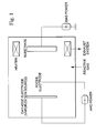
- cemented carbide substrates A1-1 to A1-6 were subjected to ultrasonic cleaning in acetone, were dried, and were then charged in a conventional arc ion plating apparatus shown in Fig. 1, and the surface of each of the cemented carbide substrates A1-1 to A1-6 was subjected to a pre-treatment under the following conditions:
- the structure of the amorphous layer formed on the surface of the cemented carbide substrates A1-1 to A1-6 was observed by using an transmission electron microscope (magnification: 500,000) and the judgment and measurement were conducted based on the observed results. As a result, the average depths (average to depths measured at five points) from the surface are shown in Table 3, respectively.
- a wear-resistant coating layer made of a Ti compound layer having a target composition and a target thickness shown in Table 1-3 was formed on the surface of these cemented carbide substrates A1-1 to A1-6 under the conditions (1-TiCN in the table represents conditions for formation of a TiCN layer with a crystal structure grown longitudinally as described in Japanese Patent Application, First Publication No. Hei 6-8010) shown in Table 1-2, thereby to produce throw-away inserts made of a surface-coated carbide alloy of this embodiment (hereinafter referred to as coated cemented carbide inserts of the present invention) 1-1 to 1-6 as the coated cemented carbide tool of the present invention, which has a shape shown in a schematic perspective view of Fig.
- coated cemented carbide inserts 1-1 to 1-10 of the present invention and the conventional coated cemented carbide inserts 1-1 to 1-10 were subjected to a dry type thick depth-of-cut interrupted cutting test of an alloy steel under the following conditions:
- Cemented carbide substrates B1-1 to B1-8 for end mills each having a size of 6 mm ⁇ 13 mm, 10 mm ⁇ 22 mm, and 20 mm ⁇ 45 mm in diameter and length of the cutting edge portion, were produced in accordance with the combination shown in Table 1-6 by preparing a WC powder of medium coarse grains having an average grain size of 5.5 ⁇ m, a WC powder of fine grains having an average grain size of 0.8 ⁇ m, a TaC powder having an average grain size of 1.3 ⁇ m, a NbC powder having an average grain size of 1.2 ⁇ m, a ZrC powder having an average grain size of 1.2 ⁇ m, a Cr 3 C 2 powder having an average grain size of 2.3 ⁇ m, a VC powder having an average grain size of 1.5 ⁇ m, a (Ti, W)C powder having an average grain size of 1.0 ⁇ m and a Co powder having an average grain size of 1.8 ⁇ m, compounding these raw powders according to each formulation in
- cemented carbide substrates B1-1 to B1-8 were subjected to ultrasonic cleaning in acetone, dried and then charged in the same arc ion plating apparatus shown in Fig. 1 and the surface of each of these cemented carbide substrates was subjected to the pre-treatment and the arc ion plating surface treatment under the same conditions as in Example 1 to form an amorphous layer on the surface of the cemented carbide substrates B1-1 to B1-8.
- the depth of the amorphous layer formed from the surface thereof was also set by controlling the treating time of the arc ion plating surface treatment under the conditions described above.
- the structure of the amorphous layer formed on the surface of the cemented carbide substrates B1-1 to B1-8 was observed by using an transmission electron microscope (magnification: 500,000) and the judgment and measurement were conducted based on the observation results. As a result, the average depth (average depths measured at five points) from the surface is shown in Table 1-7, respectively.
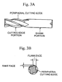
- a wear-resistant coating layer made of a Ti compound layer having a target composition and a target thickness shown in Table 1-7 was formed on the surface of these cemented carbide substrates B1-1 to B1-8 under the same conditions as shown in Table 1-2 in the state of being subjected to honing, thereby to produce end mills made of a surface-coated carbide alloy of the present invention (hereinafter referred to as coated cemented carbide end mills of the present invention) 1-1' to 1-8' as the coated cemented carbide tool of the present invention, which has a shape shown in a schematic front view of Fig. 3A and a schematic transverse cross-sectional view of Fig. 3B of the cutting edge portion.
- cemented carbide substrates C1-1 to C1-8 for drills each having a size of 4 mm ⁇ 13 mm (cemented carbide substrates C1-1 to C1-3), 8 mm ⁇ 22 mm (cemented carbide substrates C1-4 to C1-6), and 16 mm ⁇ 45 mm (cemented carbide substrates C1-7 to C1-8) in diameter and length of the flute, were produced from these three kinds of sintered round bars.
- cemented carbide substrates C1-1 to C1-8 were subjected to ultrasonic cleaning in acetone, were dried, and were then charged in the same arc ion plating apparatus shown in Fig. 1 and the surface of each of these cemented carbide substrates was subjected to the pre-treatment and the arc ion plating surface treatment under the same conditions as in Example 1 to form an amorphous layer on the surface of the cemented carbide substrates C1-1 to C1-8.
- the depth of the amorphous layer formed from the surface thereof was also set by controlling the treating time of the arc ion plating surface treatment under the conditions described above.
- the structure of the amorphous layer formed on the surface of the cemented carbide substrates C1-1 to C1-8 was observed by using an transmission electron microscope (magnification: 500,000) and the judgment and measurement were conducted based on the observed results. As a result, the average depth (average of depths measured at five points) from the surface is shown in Table 1-9, respectively.
- a wear-resistant coating layer made of a Ti compound layer having a target composition and a target thickness shown in Table 1-9 was formed on the surface of these cemented carbide substrates B1-1 to B1-8 under the same conditions as shown in Table 1-2 in the state of being subjected to honing, thereby to produce drills made of a surface-coated carbide alloy of the present invention (hereinafter referred to as coated cemented carbide drills of the present invention) 1-1" to 1-8" as the coated cemented carbide tool of the present invention, which has a shape shown in a schematic front view of Fig. 4 A and a schematic transverse cross-sectional view of Fig. 4B of the flute.
- end drills made of a conventional coated cemented carbide (hereinafter referred to as conventional coated cemented carbide drills) 1-1" to 1-8" as the conventional coated cemented carbide tool were respectively produced under the same conditions described above, except that the pre-treatment and the arc ion plating surface treatment under the above conditions to the surface of the cemented carbide substrates C1-1 to C1-8 in the arc ion plating apparatus were not conducted, and therefore, the amorphous layer was not formed on the surface of the cemented carbide substrates C1-1 to C1-8.
- coated cemented carbide drills 1-1" to 1-3" of the present invention and the conventional coated cemented carbide drills 1-1" to 1-3", among the coated cemented carbide drills 1-1" to 1-8" of the present invention were subjected to a wet type high feed drilling test of a cast iron under the following conditions:
- composition and the thickness of the hard coating layer of the coated cemented carbide inserts 1-1 to 1-10 of the present invention, the coated cemented carbide end mills 1-1' to 1-8' of the present invention and the coated cemented carbide drills 1-1" to 1-8" of the present invention as the coated cemented carbide tool of the present invention as well as the conventional coated cemented carbide inserts 1-1 to 1-10, the conventional coated cemented carbide end mills 1-1' to 1-8', and the conventional coated cemented carbide drills 1-1" to 1-8" as the conventional coated cemented carbide tool were measured by using an energy-dispersive X-ray measuring apparatus, an Auger spectrometer, and a scanning electron microscope. As a result, they exhibited the composition and average thickness (compared with an average value in thicknesses measured at five points), which are substantially the same as the target composition and the target average thickness in Table 1-3, Table 1-4, and Table 1-7 to Table 1-10.
- the second embodiment of the present invention has been carried out based on the discovered points (a) to (c) obtained in the first embodiment described above and is characterized by a coated cemented carbide tool, a hard coating layer of which has excellent adhesion, comprising: a tungsten carbide-based cemented carbide substrate having an amorphous layer formed by an arc ion plating surface treatment in an average depth of 1 to 50 nm from the surface; and a single-layered or multi-layered hard coating layer deposited physically on the surface of the tungsten carbide-based cemented carbide substrate, wherein the single-layered or multi-layered hard coating layer is made of either or both of a (Ti, Al)N layer and a (Ti, Al)CN layer, which respectively satisfy the composition formula: (Ti 1-X Al X )N and the composition formula: (Ti 1-X Al X )C 1-Y N Y (wherein X represents 0.15 to 0.65 and Y represents 0.5 to 0.99 in terms of an atomic ratio), and has
- the average thickness of the amorphous layer formed on the surface of the cemented carbide substrate, which constitutes the coated cemented carbide tool of the present invention, in the coated cemented carbide tool of this embodiment was set within a range from 1 to 50 nm for the following reasons. That is, when the depth is less than 1 nm, desired excellent adhesion between it and the TiN layer as the primary tough layer can be ensured. On the other hand, the effect of improving the adhesion of the TiN layer to the surface of the cemented carbide substrate is satisfactory when the average depth from the surface is 50 nm.
- the X value was set within a range from 0.15 to 0.65 (atomic ratio) for the following reason. That is, when the X value in the composition formula: (Ti 1-X Al X ) N and the composition formula: (Ti 1-X Al X )C 1-Y N Y is less than 0.15, desired wear resistance cannot be ensured. On the other hand, when the X value exceeds 0.65, chipping is liable to occur in the cutting edge.
- the (Ti, Al)CN layer Since the component C in the (Ti, Al)CN layer has an action of enhancing the hardness, the (Ti, Al)CN layer has a comparatively high hardness as compared with the (Ti, Al)N layer.
- the amount of the component C is less than 0.01, that is, the Y value exceeds 0.99, a predetermined effect of improving the hardness cannot be obtained.
- the amount of the component C exceeds 0.5, that is, the Y value is less than 0.5, the toughness is rapidly lowered. Therefore, the Y value was set within a range from 0.5 to 0.99, and preferably from 0.55 to 0.9.
- the reason why the average thickness of the hard coating layer was set within a range from 0.5 to 15 ⁇ m is as follows. That is, when the thickness is less than 0.5 ⁇ m, desired excellent wear resistance cannot be ensured. On the other hand, when the thickness exceeds 15 ⁇ m, chipping is liable to occur at the cutting edge.
- coated cemented carbide tool of this embodiment will be described in detail.
- Cemented carbide substrates A2-1 to A2-6, each having a shape of an insert defined in ISO ⁇ SNGA120412, and cemented carbide substrates A2-7 to A2-10, each having a shape of an insert defined in ISO SNMA120412, were produced by preparing a WC powder, a TiC powder, a ZrC powder, a VC powder, a TaC powder, a NbC powder, a Cr 3 C 2 powder, a TiN powder, a TaN powder and a Co powder, each having a predetermined average grain size of 1 to 3 ⁇ m, compounding these raw powders according to each formulation in Table 2-1, wet-mixing them in a ball mill for 72 hours, drying the mixture, compacting the dried mixture under a pressure of 100 MPa to form green compacts, vacuum-sintering these green compacts under the conditions of a vacuum degree of 6 Pa and a temperature of 1410°C for one hour, and subjecting the cutting edge portion to honing (R: 0.05).
- cemented carbide substrates A2-1 to A2-10 were subjected to ultrasonic cleaning in acetone, were dried, and then were charged in a conventional arc ion plating apparatus shown in Fig. 1 and the surface of each of the cemented carbide substrates A2-1 to A2-10 was subjected to a pre-treatment under the following conditions:
- the structure of the amorphous layer formed on the surface of the cemented carbide substrates A2-1 to A2-10 was observed by using an transmission electron microscope (magnification: 500,000) and the judgment and measurement were conducted based on the observed results.
- the average depths (average at depths measured at five points) from the surface are shown in Table 2-2 and Table 2-3, respectively.
- conventional coated cemented carbide inserts 2-1 to 2-20 (hereinafter referred to as conventional coated cemented carbide inserts) were respectively produced under the same conditions described above, except that the pre-treatment and the arc ion plating surface treatment under the above conditions to the surface of the cemented carbide substrates A2-1 to A2-10 in the arc ion plating apparatus were not conducted, and therefore, the amorphous layer was not formed on the surface of the cemented carbide substrates A2-1 to A2-10.
- coated cemented carbide inserts 2-1 to 2-20 of the present invention and the conventional coated cemented carbide inserts 2-1 to 2-20 were subjected to a dry type thick depth-of-cut interrupted cutting test of an alloy steel under the following conditions:
- Cemented carbide substrates B2-1 to B2-8 for end mill each having a size of 6 mm ⁇ 13 mm, 10 mm ⁇ 22 mm, and 20 mm ⁇ 45 mm in diameter and length of the cutting edge portion, were produced in accordance with the combination shown in Table 2-8 by preparing a WC powder of medium coarse grains having an average grain size of 5.5 ⁇ m, a WC powder of fine grains having an average grain size of 0.8 ⁇ m, a TaC powder having an average grain size of 1.3 ⁇ m, a NbC powder having an average grain size of 1.2 ⁇ m, a ZrC powder having an average grain size of 1.2 ⁇ m, a Cr 3 C 2 powder having an average grain size of 2.3 ⁇ m, a VC powder having an average grain size of 1.5 ⁇ m, a (Ti, W)C powder having an average grain size of 1.0 ⁇ m and a Co powder having an average grain size of 1.8 ⁇ m, compounding these raw powders according to each formulation in Table 2
- cemented carbide substrates B2-1 to B2-8 were subjected to ultrasonic cleaning in acetone, were dried, and were then charged in the same arc ion plating apparatus shown in Fig. 1, and the surface of each of these cemented carbide substrates was subjected to the pre-treatment and the arc ion plating surface treatment under the same conditions as in Example 1 to form an amorphous layer on the surface of the cemented carbide substrates B2-1 to B2-8.
- the depth of the amorphous layer formed from the surface thereof was also set by controlling the treating time of the arc ion plating surface treatment under the conditions described above.
- the structure of the amorphous layer formed on the surface of the cemented carbide substrates B2-1 to B2-8 was observed by using an transmission electron microscope (magnification: 500,000) and the judgment and measurement were conducted based on the observation results.
- the average depths (average in depths measured at five points) from the surface are shown in Table 2-9 and Table 2-10, respectively.
- cemented carbide substrates C2-1 to C2-8 for drills each having a size of 4 mm ⁇ 13 mm (cemented carbide substrates C2-1 to C2-3), 8 mm ⁇ 22 mm (cemented carbide substrates C2-4 to C2-6), and 16 mm ⁇ 45 mm (cemented carbide substrates C2-7 to C2-8), in diameter and length of the flute, were produced fromthese three kinds of sintered round bars.
- cemented carbide substrates C2-1 to C2-8 were subjected to ultrasonic cleaning in acetone, dried and then charged in the same arc ion plating apparatus shown in Fig. 1 and the surface of each of these cemented carbide substrates was subjected to the pre-treatment and the arc ion plating surface treatment under the same conditions as in Example 1 to form an amorphous layer on the surface of the cemented carbide substrates C2-1 to C2-8.
- the depth of the amorphous layer formed from the surface thereof was also set by controlling the treating time of the arc ion plating surface treatment under the conditions described above.
- the structure of the amorphous layer formed on the surface of the cemented carbide substrates C2-1 to C2-8 was observed by using an transmission electron microscope (magnification: 500,000) and the judgment and measurement were conducted based on the observed results.
- the average depths (average of depths measured at five points) from the surface are shown in Table 2-13 and Table 2-14, respectively.
- end drills made of a conventional coated cemented carbide (hereinafter referred to as conventional coated cemented carbide drills) 2-1" to 2-16" as the conventional coated cemented carbide tool were respectively produced under the same conditions described above, except that the pre-treatment and the arc ion plating surface treatment under the above conditions to the surface of the cemented carbide substrates C2-1 to C2-8 in the arc ion plating apparatus were not conducted, and therefore, the amorphous layer was not formed on the surface of the cemented carbide substrates C1-1 to C1-8.
- the third embodiment of the present invention has been carried out based on the discovered points (a) to (c).
- This embodiment is characterized by a coated cemented carbide tool, a wear-resistant coating layer of which has excellent adhesion, comprising: a tungsten carbide-based cemented carbide substrate having an amorphous layer formed by an arc ion plating surface treatment to an average depth of 1 to 50 nm from the surface; and a wear-resistant coating layer deposited physically and/or chemically on the surface of the tungsten carbide-based cemented carbide substrate, wherein a wear-resistant coating layer is composed of: (a) a lower coating layer which is made of one layer or a plurality of two or more layers, among a TiC layer, a TiN layer, a TiCN layer, a TiCO layer and a TiCNO layer (hereinafter generically referred to as a Ti compound layer), and has an average thickness of 0.5 to 15 ⁇ m; and (b) an upper coating layer which is made of either or
- the amorphous layer formed on the surface of the cemented carbide substrate has an action of imparting excellent adhesion between it and the wear-resistant coating layer(lower coating layer), as described above.
- the depth is less than 1 nm, desired excellent adhesion cannot be ensured.
- the effect of improving the adhesion of the lower coating layer on the surface of the cemented carbide substrate is satisfactory when the average depth from the surface is 50 nm. Therefore, the average depth was set within a range from 1 to 50 nm.
- a Ti compound layer constituting the lower coating layer basically has an action of improving the toughness of the wear-resistant coating layer, thereby remarkably suppressing chipping from occurring in the wear-resistant coating layer even in the interrupted cutting operation accompanied with high mechanical and thermal impacts under deep cutting conditions.
- the average thickness is less than 0.5 ⁇ m, desired toughness cannot be ensured in the wear-resistant coating layer.
- the average thickness exceeds 15 ⁇ m, plastic deformation, which is likely to cause biased wear, is liable to occur in the wear-resistant coating layer in the interrupted cutting operation under deep cutting conditions. Therefore, the average depth was set within a range from 0.5 to 15 ⁇ m.
- the Al 2 O 3 layer and the Al 2 O 3 -ZrO 2 mixed layer, which constitute the upper coating layer, have an action of imparting the hardness and heat resistance to the wear-resistant coating layer, thereby exhibiting excellent wear resistance without causing chipping in the co-existing lower coating layer.
- the average thickness is less than 0.5 ⁇ m, desired excellent wear resistance cannot be ensured.
- the average thickness exceeds 15 ⁇ m, chipping is liable to occur in the wear-resistant coating layer. Therefore, the average depth was set within a range from 0.5 to 15 ⁇ m.
- coated cemented carbide tool of this embodiment will be described in detail.
- cemented carbide substrates A3-1 to A3-6 were subjected to ultrasonic cleaning in acetone, were dried, and were then charged in a conventional arc ion plating apparatus shown in Fig. 1 and the surface of each of the cemented carbide substrates A-F was subjected to a pre-treatment under the following conditions:
- the structure of the amorphous layer formed on the surface of the cemented carbide substrates A3-1 to A3-6 was observed by using an transmission electron microscope (magnification: 500,000) and the judgment and measurement were conducted based on the observation results. As a result, the average depth (average of depths measured at five points) from the surface is shown in Table 3-3, respectively.
- a wear-resistant coating layer composed of a Ti compound layer (lower coating layer) having a target composition and a target thickness shown in Table 3-3 and an Al 2 O 3 layer and/or an Al 2 O 3 -ZrO 2 mixed layer (upper coating layer) was formed on the surface of these cemented carbide substrates A3-1 to A3-6 under the conditions (1-TiCN in the table represents conditions for formation of a TiCN layer with a crystal structure grown longitudinally as described in Japanese Patent Application, First Publication No.
- coated cemented carbide inserts of the present invention 3-1 to 3-10 as the coated cemented carbide tool of the present invention, which has a shape shown in a schematic perspective view of Fig. 2A and a schematic longitudinal cross-sectional view of Fig. 2B.
- conventional coated cemented carbide inserts 3-1 to 3-10 (hereinafter referred to as conventional coated cemented carbide inserts) were respectively produced under the same conditions described above, except that the pre-treatment and the arc ion plating surface treatment under the above conditions to the surface of the cemented carbide substrates A3-1 to A3-6 in the arc ion plating apparatus were not conducted, and therefore, the amorphous layer was not formed on the surface of the cemented carbide substrates A3-1 to A3-6.
- coated cemented carbide inserts 3-1 to 3-10 of the present invention and the conventional coated cemented carbide inserts 3-1 to 3-10 were subjected to a dry type thick depth-of-cut interrupted cutting test of an alloy steel under the following conditions:
- Cemented carbide substrates B3-1 to B3-8 for end mill each having a size of 6 mm ⁇ 13 mm, 10 mm ⁇ 22 mm, and 20 mm ⁇ 45 mm in diameter and length of the cutting edge portion, were produced in accordance with the combination shown in Table 3-6 by preparing a WC powder of medium coarse grains having an average grain size of 5.5 ⁇ m, a WC powder of fine grains having an average grain size of 0.8 ⁇ m, a TaC powder having an average grain size of 1.3 ⁇ m, a NbC powder having an average grain size of 1.2 ⁇ m, a ZrC powder having an average grain size of 1.2 ⁇ m, a Cr 3 C 2 powder having an average grain size of 2.3 ⁇ m, a VC powder having an average grain size of 1.5 ⁇ m, a (Ti, W)C powder having an average grain size of 1.0 ⁇ m and a Co powder having an average grain size of 1.8 ⁇ m, compounding these raw powders according to each formulation in Table
- cemented carbide substrates B3-1 to B3-8 were subjected to ultrasonic cleaning in acetone, were dried, and were then charged in the same arc ion plating apparatus shown in Fig. 1 and the surface of each of these cemented carbide substrates was subjected to the pre-treatment and the arc ion plating surface treatment under the same conditions as in Example 1 to form an amorphous layer on the surface of the cemented carbide substrates B3-1 to B3-8.
- the depth of the amorphous layer formed from the surface thereof was also set by controlling the treating time of the arc ion plating surface treatment under the conditions described above.
- the structure of the amorphous layer formed on the surface of the cemented carbide substrates B3-1 to B3-8 was observed by using an transmission electron microscope (magnification: 500,000) and the judgment and measurement were conducted based on the observed results. As a result, the average depth (average of depths measured at five points) from the surface is shown in Table 3-7, respectively.
- a wear-resistant coating layer composed of a Ti compound layer (lower coating layer) having a target composition and a target thickness shown in Table 3-7 and an Al 2 O 3 layer and/or an Al 2 O 3 -ZrO 2 mixed layer (upper coating layer) was formed on the surface of these cemented carbide substrates under the conditions shown in Table 3-2, thereby producing end mills made of a surface-coated carbide alloy of the present invention (hereinafter referred to as coated cemented carbide end mills of the present invention) 3-1' to 3-8' as the coated cemented carbide tool of the present invention, which has a shape shown in a schematic front view of Fig. 3A and a schematic transverse cross-sectional view of Fig. 3B of the cutting edge portion.
- coated cemented carbide end mills 3-4' to 3-6' of the present invention and the conventional coated cemented carbide end mills 3-4' to 3-6' were subjected to a wet type thick depth-of-cut side cutting test of a carbon steel under the following conditions:
- coated cemented carbide end mills 3-7' to 3-8' of the present invention and the conventional coated cemented carbide end mills 3-7' to 3-8' were subjected to a wet type thick depth-of-cut side cutting test of a hardened steel under the following conditions:
- cemented carbide substrates C3-1 to C3-8 for drills each having a size of 4 mm ⁇ 13 mm (cemented carbide substrates C3-1 to C3-3), 8 mm ⁇ 22 mm (cemented carbide substrates C3-4 to C3-6), and 16 mm ⁇ 45 mm (cemented carbide substrates C3-7 to C3-8) in diameter and length of the flute, were produced from these three kinds of sintered round bars.
- cemented carbide substrates C3-1 to C3-8 were subjected to ultrasonic cleaning in acetone, were dried, and were then charged in the same arc ion plating apparatus shown in Fig. 1 and the surface of each of these cemented carbide substrates was subjected to the pre-treatment and the arc ion plating surface treatment under the same conditions as in Example 1 to form an amorphous layer on the surface of the cemented carbide substrates C3-1 to C3-8.
- the depth of the amorphous layer formed from the surface thereof was also set by controlling the treating time of the arc ion plating surface treatment under the conditions described above.
- the structure of the amorphous layer formed on the surface of the cemented carbide substrates C3-1 to C3-8 was observed by using an transmission electron microscope (magnification: 500,000) and the judgment and measurement were conducted based on the observed results. As a result, the average depths (average of depths measured at five points) from the surface are shown in Table 3-9, respectively.
- a wear-resistant coating layer composed of a Ti compound layer (lower coating layer) having a target composition and a target thickness shown in Table 3-9 and an Al 2 O 3 layer and/or an Al 2 O 3 -ZrO 2 mixed layer (upper coating layer) was formed on the surface of these cemented carbide substrates under the conditions shown in Table 3-2, thereby producing drills made of a surface-coated carbide alloy of the present invention (hereinafter referred to as coated cemented carbide drills of the present invention) 3-1 to 3-8 as the coated cemented carbide tool of the present invention, which has a shape shown in a schematic front view of Fig. 4A and a schematic transverse cross-sectional view of Fig. 4B of the flute.
- end drills made of a conventional coated cemented carbide (hereinafter referred to as conventional coated cemented carbide drills) 3-1" to 3-8" as the conventional coated cemented carbide tool were respectively produced under the same conditions described above, except that the pre-treatment and the arc ion plating surface treatment under the above conditions on the surface of the cemented carbide substrates C3-1 to C3-8 in the arc ion plating apparatus were not conducted, and therefore, the amorphous layer was not formed on the surface of the cemented carbide substrates C3-1 to C3-8.
- the coated cemented carbide drills 3-1" to 3-3" of the present invention and the conventional coated cemented carbide drills 3-1" to 3-3", among the coated cemented carbide drills 3-1" to 3-8" of the present invention and the conventional coated cemented carbide drills 3-1" to 3-8", were subjected to a wet type high feed drilling test of a cast iron under the following conditions:
- composition and the thickness of the hard coating layer of the coated cemented carbide inserts 3-1 to 3-10 of the present invention, the coated cemented carbide end mills 3-1' to 3-8' of the present invention, and the coated cemented carbide drills 3-1" to 3-8" of the present invention as the coated cemented carbide tool of the present invention as well as the conventional coated cemented carbide inserts 3-1 to 3-10, the conventional coated cemented carbide end mills 3-1' to 3-8', and the conventional coated cemented carbide drills 3-1" to 3-8" as the conventional coated cemented carbide tool were measured by using an energy-dispersive X-ray measuring apparatus, an Auger spectrometer, and a scanning electron microscope. As a result, they exhibited the composition and average thickness (compared with an average value of thicknesses measured at five points), which are substantially the same as the target composition and the target average thickness in Table 3-3, Table 3-4 and Table 3-7 to Table 3-10.
- This invention has been made based on the discovered point described above and is characterized by a coated cemented carbide tool, a wear-resistant coating layer of which excellent adhesion and resistance against chipping, comprising: a tungsten carbide-based cemented carbide substrate having an amorphous layer formed by an arc ion plating surface treatment in an average depth of 1 to 50 nm from the surface; and a wear-resistant coating layer deposited physically on the surface of the tungsten carbide-based cemented carbide substrate, wherein wear-resistant coating layer is composed of: (a) a primary tough layer which is made of a TiN layer and has an average thickness of 0.1 to 5 ⁇ m; and (b) a single-layered or multi-layered surface hard layer which is made of either or both of a (Ti, Al)N layer and a (Ti, Al)CN layer, which respectively satisfy the composition formula: (Ti 1-X Al X )N and the composition formula: (Ti 1-X Al X )C 1-Y N Y (
- the average thickness of the amorphous layer formed on the surface of the cemented carbide substrate, which constitutes the coated cemented carbide tool of the present invention was set within a range from 1 to 50 nm for the following reasons. That is, when the depth is less than 1 nm, desired excellent adhesion between it and the TiN layer as the primary tough layer can be ensured. On the other hand, the effect of improving the adhesion of the TiN layer to the surface of the cemented carbide substrate is satisfactory when the average depth from the surface is 50 nm.
- the X value was set within a range from 0.15 to 0.65 (atomic ratio) for the following reason. That is, when the X value in the composition formula: (Ti 1-X Al X )N and the composition formula: (Ti 1-X Al X )C 1-Y N Y is less than 0.15, desired wear resistance cannot be ensured. On the other hand, when the X value exceeds 0.65, chipping is liable to occur in the cutting edge.
- the (Ti, Al)CN layer Since the component C in the (Ti, Al)CN layer has an action of enhancing the hardness, the (Ti, Al)CN layer has a relatively high hardness as compared with the (Ti, Al)N layer.
- the amount of the component C is less than 0.01, that is, the Y value exceeds 0.99, a predetermined effect of improving the hardness cannot be obtained.
- the amount of the component C exceeds 0.5, that is, the Y value is less than 0.5, the toughness is rapidly lowered. Therefore, the Y value was set within a range from 0.5 to 0.99, and preferably from 0.55 to 0.9.
- the reason why the average thickness of the surface hard layer was set within a range from 0.5 to 15 ⁇ m is as follows. That is, when the thickness is less than 0.5 ⁇ m, desired excellent wear resistance cannot be ensured. On the other hand, when the thickness exceeds 15 ⁇ m, chipping is liable to occur at the cutting edge.
- the reason why the average thickness of the lower tough layer was set within a range from 0.1 to 5 ⁇ m is as follows. That is, when the thickness is less than 0.1 ⁇ m, desired toughness cannot be ensured in the wear-resistant coating layer. On the other hand, when the thickness exceeds 5 ⁇ m, plastic deformation, which is likely to cause biased wear, is liable to occur in the wear-resistant coating layer in the interrupted cutting operation under deep cutting conditions.
- coated cemented carbide tool of this embodiment will be described in detail.
- Cemented carbide substrates A4-1 to A4-6 each having a shape of an insert defined in ISO ⁇ SNGA120412, and cemented carbide substrates A4-7 to A4-10, each having a shape of an insert defined in ISO ⁇ SNMA120412, were produced by preparing a WC powder, a TiC powder, a ZrC powder, a VC powder, a TaC powder, a NbC powder, a Cr 3 C 2 powder, a TiN powder, a TaN powder and a Co powder, each having a predetermined average grain size of 1 to 3 ⁇ m, compounding these raw powders according to each formulation in Table 1, wet-mixing them in a ball mill for 72 hours, drying the mixture, compacting the dried mixture under a pressure of 100 MPa to form green compacts, vacuum-sintering these green compacts under the conditions of a vacuum degree of 6 Pa, a temperature of 1400°C for one hour, and subjecting the cutting edge portion to honing (R: 0.05).
- cemented carbide substrates A4-1 to A4-10 were subjected to ultrasonic cleaning in acetone, were dried, and were then charged in a conventional arc ion plating apparatus shown in Fig. 1 and the surface of each of the cemented carbide substrates A4-1 to A4-10 was subjected to a pre-treatment under the following conditions:
- the structure of the amorphous layer formed on the surface of the cemented carbide substrates A4-1 to A4-10 was observed by using an transmission electron microscope (magnification: 500,000) and the judgment and measurement were conducted based on the observed results.
- the average depths (average of depths measured at five points) from the surface are shown in Table 4-2 and Table 4-3, respectively.
- throw-away inserts made of a conventional coated cemented carbide (hereinafter referred to as conventional coated cemented carbide inserts) 4-1 to 4-20 were respectively produced under the same conditions described above, except that the pre-treatment and the arc ion plating surface treatment under the above conditions to the surface of the cemented carbide substrates A4-1 to A4-10 in the arc ion plating apparatus were not conducted, and therefore, the amorphous layer did not exist on the surface of the cemented carbide substrates A4-1 to A4-10 and the TiN layer as the primary tough layer was not formed.
- coated cemented carbide inserts 4-1 to 4-20 of the present invention and the conventional coated cemented carbide inserts 4-1 to 4-20 were subjected to a dry type thick depth-of-cut interrupted cutting test of an alloy steel under the following conditions:
- Cemented carbide substrates B4-1 to B4-8 for end mill each having a size of 6 mm ⁇ 13 mm, 10 mm ⁇ 22 mm, and 20 mm ⁇ 45 mm in diameter and length of the cutting edge portion, were produced in accordance with the combination shown in Table 4-8 by preparing a WC powder of medium coarse grains having an average grain size of 5.5 ⁇ m, a WC powder of fine grains having an average grain size of 0.8 ⁇ m, a TaC powder having an average grain size of 1.3 ⁇ m, a NbC powder having an average grain size of 1.2 ⁇ m, a ZrC powder having an average grain size of 1.2 ⁇ m, a Cr 3 C 2 powder having an average grain size of 2.3 ⁇ m, a VC powder having an average grain size of 1.5 ⁇ m, a (Ti, W)C powder having an average grain size of 1.0 ⁇ m and a Co powder having an average grain size of 1.8 ⁇ m, compounding these raw powders according to each formulation in Table
- cemented carbide substrates B4-1 to B4-8 were subjected to ultrasonic cleaning in acetone, were dried, and were then charged in the same arc ion plating apparatus shown in Fig. 1, and the surface of each of these cemented carbide substrates was subjected to the pre-treatment and the arc ion plating surface treatment under the same conditions as in Example 1 to form an amorphous layer on the surface of the cemented carbide substrates B4-1 to B4-8.
- the depth of the amorphous layer formed from the surface thereof was also set by controlling the treating time of the arc ion plating surface treatment under the conditions described above.
- the structure of the amorphous layer formed on the surface of the cemented carbide substrates B4-1 to B4-8 was observed by using a transmission electron microscope (magnification: 500,000) and the judgment and measurement were conducted based on the observation results.
- the average depths (average of depths measured at five points) from the surface are shown in Table 4-9 and Table 4-10, respectively.
- a TiN layer, as the primary tough layer, having a target thickness shown in Table 4-9 and Table 4-10 was deposited on the surface of these cemented carbide substrates, and then a single-layered or multi-layered surface hard layer of either or both of a (Ti, Al)N layer and a (Ti, Al)CN layer, which have a target composition and a target thickness shown in Table 4-9 and 4-10, was formed thereon, thereby producing end mills made of a surface-coated carbide alloy of the present invention (hereinafter referred to as coated cemented carbide end mills of the present invention) 4-1' to 4-16' as the coated cemented carbide tool of the present invention, which has a shape shown in a schematic front view of Fig. 3A and a schematic transverse cross-sectional view of Fig. 3B of the cutting edge portion.
- the coated cemented carbide end mills 4-1' to 4-3' and 4-9' to 4-11' of the present invention and the conventional coated cemented carbide end mills 4-1' to 4-3' and 4-9' to 4-11', among the coated cemented carbide end mills 4-1' to 4-16' of the present invention and the conventional coated cemented carbide end mills 4-1' to 4-16', were subjected to a wet type thick depth-of-cut side cutting test of a cast iron under the following conditions:
- coated cemented carbide end mills 4-4' to 4-6' and 4-12' to 4-14' of the present invention and the conventional coated cemented carbide end mills 4-4' to 4-6' and 4-12' to 4-14' were subjected to a wet type thick depth-of-cut side cutting test of a cast iron under the following conditions:
- coated cemented carbide end mills 4-7', 4-8', 4-15' and 4-16' of the present invention and the conventional coated cemented carbide end mills 4-7', 4-8', 4-15' and 4-16' were subjected to a wet type thick depth-of-cut side cutting test of a hardened steel under the following conditions:
- cemented carbide substrates C4-1 to C4-8 for drills each having a size of 4 mm ⁇ 13 mm (cemented carbide substrates C4-1 to C4-3), 8 mm ⁇ 22 mm (cemented carbide substrates C4-4 to C4-6), and 16 mm ⁇ 45 mm (cemented carbide substrates C4-7 to C4-8) in diameter and length of the flute, were produced from these three kinds of sintered round bars.
- cemented carbide substrates C4-1 to C4-8 were subjected to ultrasonic cleaning in acetone, were dried, and were then charged in the same arc ion plating apparatus shown in Fig. 1, and the surface of each of these cemented carbide substrates was subjected to the pre-treatment and the arc ion plating surface treatment under the same conditions as in Example 1 to form an amorphous layer on the surface of the cemented carbide substrates C4-1 to C4-8.
- the depth of the amorphous layer formed from the surface thereof was also set by controlling the treating time of the arc ion plating surface treatment under the conditions described above.
- the structure of the amorphous layer formed on the surface of the cemented carbide substrates C4-1 to C4-8 was observed by using a transmission electron microscope (magnification: 500,000) and the judgment and measurement were conducted based on the observation results.
- the average depths (average of depths measured at five points) from the surface are shown in Table 4-13 and Table 4-14, respectively.
- a TiN layer, as the primary tough layer, having a target thickness shown in Table 4-13 and Table 4-14 was deposited on the surface of these cemented carbide substrates under the same conditions as in Example 1, and then a single-layered or multi-layered surface hard layer of either or both of a (Ti, Al)N layer and a (Ti, A1)CN layer, which have a target composition and a target thickness shown in Table 4-13 and 4-14, was formed thereon, thereby producing drills made of a surface-coated carbide alloy of the present invention (hereinafter referred to as coated cemented carbide drills of the present invention) 4-1" to 4-16" as the coated cemented carbide tool of the present invention, which has a shape shown in a schematic front view of Fig. 4A and a schematic transverse cross-sectional view of Fig. 4B of the flute.
- end drills made of a conventional coated cemented carbide (hereinafter referred to as conventional coated cemented carbide drills) 4-1" to 4-16" as the conventional coated cemented carbide tool were respectively produced under the same conditions described above, except that the pre-treatment and the arc ion plating surface treatment under the above conditions to the surface of the cemented carbide substrates C4-1 to C4-8 in the arc ion plating apparatus were not conducted, and therefore, the amorphous layer did not exist on the surface of the cemented carbide substrates C1-1 to C1-8 and the TiN layer as the primary tough layer was not formed.
- the coated cemented carbide drills 4-1" to 4-3" and 4-9" to 4-11" of the present invention and the conventional coated cemented carbide drills 4-1" to 4-3" and 4-9" to 4-11", among the coated cemented carbide drills 4-1" to 4-16" of the present invention and the conventional coated cemented carbide drills 4-1" to 4-16", were subjected to a wet type high feed drilling test of a cast iron under the following conditions:
- coated cemented carbide drills 4-4" to 4-6" and 4-12" to 4-14" of the present invention and the conventional coated cemented carbide drills 4-4" to 4-6" and 4-12" to 4-14" were subjected to a wet type high feed drilling test of an alloy steel under the following conditions:
- coated cemented carbide drills 4-7", 4-8", 4-15” and 4-16" of the present invention and the conventional coated cemented carbide drills 4-7", 4-8", 4-15” and 4-16" were subjected to a wet type high feed drilling test of a hardened steel under the following conditions:
- the fifth embodiment was carried out to produce a cutting tool for a surface-coated carbide alloy, wherein the adhesion of a wear-resistant layer to a cemented carbide has been improved further, based on the discovered points (a) to (c) described above.
- This embodiment is characterized by a coated cemented carbide tool, a wear-resistant coating layer of which has excellent adhesion and resistance against chipping, comprising:
- the amorphous layer has an action of imparting excellent adhesion between it and the wear-resistant coating layer (primary tough layer), as described above.
- the wear-resistant coating layer primary tough layer
- the depth is less than 1 nm
- desired excellent adhesion between it and the TiN layer as the primary tough layer cannot be ensured.
- the effect of improving the adhesion of the wear-resistant layer to the surface of the cemented carbide substrate is satisfactory when the average depth from the surface is 50 nm. Therefore, the average depth was set within a range from 1 to 50 nm.
- the primary tough layer has an action of improving the toughness of the wear-resistant coating layer, thereby remarkably suppressing chipping from occurring in the wear-resistant coating layer even in the interrupted cutting operation accompanied with high mechanical and thermal impacts under deep cutting conditions, as described above.
- the average thickness is less than 0.1 ⁇ m, desired toughness cannot be ensured in the wear-resistant coating layer.
- the average thickness exceeds 5 ⁇ m, plastic deformation, which is likely to cause biased wear, is liable to occur in the wear-resistant coating layer in the interrupted cutting operation under deep cutting conditions. Therefore, the average depth was set within a range from 0.1 to 5 ⁇ m.
- the (Ti, Al)N layer and the (Ti, Al)CN layer, which constitute the lower hard coating layer, have an action of imparting the hardness and toughness to the wear-resistant coating layer, thereby exhibiting excellent wear resistance without causing chipping in the co-existence of the lower coating layer. That is, Al in the lower hard layer is incorporated into TiN having high toughness in the form of a solid solution for the purpose of enhancing the hardness, thereby improveing the wear resistance. Therefore, the X value was set within a range from 0.15 to 0.65 (atomic ratio) for the following reason.
- the Y value was set within a range from 0.5 to 0.99, and preferably from 0.55 to 0.9.
- the average thickness is less than 0.5 ⁇ m, desired excellent wear resistance cannot be ensured. On the other hand, when the thickness exceeds 15 ⁇ m, chipping is liable to occur at the cutting edge. Therefore, the average thickness was set within a range from 0.5 to 15 ⁇ m.
- the Al 2 O 3 layer and the Al 2 O 3 -ZrO 2 mixed layer, which constitute the upper hard layer, have excellent hardness at high temperature and heat resistance and also have an action of noticeably improving the wear-resistant coating layer in the co-existence of the lower coating layer described above.
- the average thickness is less than 0.5 ⁇ m, desired excellent wear resistance cannot be ensured.
- the average thickness exceeds 10 ⁇ m, chipping is liable to occur at the wear-resistant coating layer. Therefore, the average depth was set within a range from 0.5 to 10 ⁇ m.
- coated cemented carbide tool of this embodiment will be described in detail.
- Cemented carbide substrates A5-1 to A5-10 each having a shape of an insert defined in ISO ⁇ SNGA120412, were produced by preparing a WC powder, a TiC powder, a ZrC powder, a VC powder, a TaC powder, a NbC powder, a Cr 3 C 2 powder, a TiN powder, a TaN powder and a Co powder, each having a predetermined average grain size of 1 to 3 ⁇ m, compounding these raw powders according to each formulation in Table 5-1, wet-mixing them in a ball mill for 72 hours, drying the mixture, compacting the dried mixture under a pressure of 100 MPa to form green compacts, vacuum-sintering these green compacts under the conditions of a vacuum degree of 6 Pa, a temperature of 1400°C for one hour, and subjecting the cutting edge portion to honing (R: 0.05).
- cemented carbide substrates A5-1 to A5-10 were subjected to ultrasonic cleaning in acetone, were dried, and were then charged in a conventional arc ion plating apparatus shown in Fig. 1 and the surface of each of the cemented carbide substrates A5-1 to A5-10 was subjected to a pre-treatment under the following conditions:
- the structure of the amorphous layer formed on the surface of the cemented carbide substrates A5-1 to A5-10 was observed by using a transmission electron microscope (magnification: 500,000) and the judgment and measurement were conducted based on the observation results.
- the average depth (average of depths measured at five points) from the surface are shown in Table 5-3 and Table 5-5, respectively.
- throw-away inserts made of a conventional coated cemented carbide (hereinafter referred to as conventional coated cemented carbide inserts) 5-1 to 5-20 were respectively produced under the same conditions described above, except that the pre-treatment and the arc ion plating surface treatment under the above conditions to the surface of the cemented carbide substrates A5-1 to A5-10 in the arc ion plating apparatus were not conducted, and therefore, the amorphous layer was not formed on the surface of the cemented carbide substrates A5-1 to A5-10 and also the TiN layer as the primary tough layer was not formed.
- coated cemented carbide inserts 5-1 to 5-20 of the present invention and the conventional coated cemented carbide inserts 5-1 to 5-20 were subjected to a dry type thick depth-of-cut interrupted cutting test of an alloy steel under the following conditions:
- Cemented carbide substrates B5-1 to B5-8 for end mill each having a size of 6 mm ⁇ 13 mm, 10 mm ⁇ 22 mm, and 20 mm ⁇ 45 mm in diameter and length of the cutting edge portion, were produced in accordance with the combination shown in Table 5-11 by preparing a WC powder of medium coarse grains having an average grain size of 5.5 ⁇ m, a WC powder of fine grains having an average grain size of 0.8 ⁇ m, a TaC powder having an average grain size of 1.3 ⁇ m, a NbC powder having an average grain size of 1.2 ⁇ m, a ZrC powder having an average grain size of 1.2 ⁇ m, a Cr 3 C 2 powder having an average grain size of 2.3 ⁇ m, a VC powder having an average grain size of 1.5 ⁇ m, a (Ti, W)C powder having an average grain size of 1.0 ⁇ m and a Co powder having an average grain size of 1.8 ⁇ m, compounding these raw powders according to each formulation in Table 5
- cemented carbide substrates B5-1 to B5-8 were subjected to ultrasonic cleaning in acetone, were dried, and werethen charged in the same arc ion plating apparatus shown in Fig. 1 and the surface of each of these cemented carbide substrates was subjected to the pre-treatment and the arc ion plating surface treatment under the same conditions as in Example 1 to form an amorphous layer on the surface of the cemented carbide substrates B5-1 to B5-8.
- the depth of the amorphous layer formed from the surface thereof was also set by controlling the treating time of the arc ion plating surface treatment under the conditions described above.
- the structure of the amorphous layer formed on the surface of the cemented carbide substrates B5-1 to B5-8 was observed by using a transmission electron microscope (magnification: 500,000) and the judgment and measurement were conducted based on the observation results.
- the average depth (average in depths measured at five points) from the surface is shown in Table 5-12 and Table 5-14, respectively.
- a TiN layer, as the primary tough layer, having a target thickness shown in Table 5-12 and Table 5-14 was deposited on the surface of these cemented carbide substrates under the same conditions as in Example 1, and then a single-layered or multi-layered lower hard layer of either or both of a (Ti, Al)N layer and a (Ti, Al)CN layer, which have a target composition and a target thickness shown in Table 5-12 and 5-14, was formed on the surface thereof and, furthermore, an ⁇ - or ⁇ -type crystal structure Al 2 O 3 layer having a target structure shown in Table 5-13 and Table 5-15 or an Al 2 O 3 -ZrO 2 mixed layer, as the upper hard layer, was deposited on the surface of the lower hard layer under the same conditions as shown in Table 5-2, using a conventional chemical deposition apparatus, thereby producing end mills made of a surface-coated carbide alloy of the present invention (hereinafter referred to as coated cemented carbide end mills of
- coated cemented carbide end mills 5-4' to 5-6' and 5-12' to 5-14' of the present invention and the conventional coated cemented carbide end mills 5-4' to 5-6' and 5-12' to 5-14' were subjected to a wet type thick depth-of-cut side cutting test of an alloy steel under the following conditions:
- coated cemented carbide end mills 5-7', 5-8', 5-15' and 5-16' of the present invention and the conventional coated cemented carbide end mills 5-7', 5-8', 5-15' and 5-16' were subjected to a wet type thick depth-of-cut side cutting test of a hardened steel under the following conditions:
- cemented carbide substrates C5-1 to C5-8 for drills each having a size of 4 mm ⁇ 13 mm (cemented carbide substrates C5-1 to C5-3), 8 mm ⁇ 22 mm (cemented carbide substrates C5-4 to C5-6), and 16 mm ⁇ 45 mm (cemented carbide substrates C5-7 to C5-8) in diameter and length of the flute, were produced from these three kinds of sintered round bars.
- cemented carbide substrates C5-1 to C5-8 were subjected to ultrasonic cleaning in acetone, were dried, and were then charged in the same arc ion plating apparatus shown in Fig. 1 and the surface of each of these cemented carbide substrates was subjected to the pre-treatment and the arc ion plating surface treatment under the same conditions as in Example 1 to form an amorphous layer on the surface of the cemented carbide substrates C5-1 to C5-8.
- the depth of the amorphous layer formed from the surface thereof was also set by controlling the treating time of the arc ion plating surface treatment under the conditions described above.
- the structure of the amorphous layer formed on the surface of the cemented carbide substrates C5-1 to C5-8 was observed by using a transmission electron microscope (magnification: 500,000) and the judgment and measurement were conducted based on the observation results.
- the average depth (average in depths measured at five points) from the surface is shown in Table 5-20 and Table 5-22, respectively.
- a TiN layer, as the primary tough layer, having a target thickness shown in Table 5-13 and Table 5-14 was deposited on the surface of these cemented carbide substrates under the same conditions as in Example 1, and then a single-layered or multi-layered lower hard layer of either or both of a (Ti, Al)N layer and a (Ti, Al)CN layer, which have a target composition and a target thickness shown in Table 5-20 and 5-22, was formed on the surface thereof and, furthermore, an ⁇ - or ⁇ -type crystal structure Al 2 O 3 layer having a target structure shown in Table 5-21 and Table 5-23 or an Al 2 O 3 -ZrO 2 mixed layer, as the upper hard layer, was deposited on the surface of the lower hard layer under the same conditions as shown in Table 5-2, using a conventional chemical deposition apparatus, thereby to produce drills made of a surface-coated carbide alloy of the present invention (hereinafter referred to as coated cemented carbide drills of the
- end drills made of a conventional coated cemented carbide (hereinafter referred to as conventional coated cemented carbide drills) 5-1" to 5-16" as the conventional coated cemented carbide tool were respectively produced under the same conditions described above, except that the pre-treatment and the arc ion plating surface treatment under the above conditions to the surface of the cemented carbide substrates C5-1 to C5-8 in the arc ion plating apparatus were not conducted, and therefore, the amorphous layer did not exist on the surface of the cemented carbide substrates C1-1 to C1-8 and the TiN layer as the primary tough layer was not formed.
- the coated cemented carbide drills 5-1" to 5-3" and 5-9" to 5-11" of the present invention and the conventional coated cemented carbide drills 5-1" to 5-3" and 5-9" to 5-11", among the coated cemented carbide drills 5-1" to 5-16" of the present invention and the conventional coated cemented carbide drills 5-1" to 5-16", were subjected to a wet type high feed drilling test of a cast iron under the following conditions:
- coated cemented carbide drills 5-4" to 5-6" and 5-12" to 5-14" of the present invention and the conventional coated cemented carbide drills 5-4" to 5-6" and 5-12" to 5-14" were subjected to a wet type high feed drilling test of an alloy steel under the following conditions:
- coated cemented carbide drills 5-7", 5-8", 5-15" and 5-16" of the present invention and the conventional coated cemented carbide drills 5-7", 5-8", 5-15” and 5-16" were subjected to a wet type high feed drilling test of a hardened steel under the following conditions:
- composition and the thickness of the hard coating layer of the coated cemented carbide inserts 5-1 to 5-20 of the present invention, the coated cemented carbide end mills 5-1' to 5-16' of the present invention, and the coated cemented carbide drills 5-1" to 5-16" of the present invention as the coated cemented carbide tool of the present invention as well as the conventional coated cemented carbide inserts 5-1 to 5-20, the conventional coated cemented carbide end mills 5-1' to 5-16', and the conventional coated cemented carbide drills 5-1" to 5-16” as the conventional coated cemented carbide tool were measured by using an energy-dispersive X-ray measuring apparatus, an Auger spectrometer, and a scanning electron microscope. As a result, they exhibited the composition and average thickness (compared with an average value of thicknesses measured at five points), which are substantially the same as the target composition and the target average thickness in Table 5-3 to Table 5-10 and Table 5-12 to Table 5-27.
Landscapes
- Chemical & Material Sciences (AREA)
- Chemical Kinetics & Catalysis (AREA)
- Engineering & Computer Science (AREA)
- Materials Engineering (AREA)
- Mechanical Engineering (AREA)
- Metallurgy (AREA)
- Organic Chemistry (AREA)
- Cutting Tools, Boring Holders, And Turrets (AREA)
- Physical Vapour Deposition (AREA)
Applications Claiming Priority (22)
| Application Number | Priority Date | Filing Date | Title |
|---|---|---|---|
| JP2001175217 | 2001-06-11 | ||
| JP2001175217 | 2001-06-11 | ||
| JP2001192496 | 2001-06-26 | ||
| JP2001192496 | 2001-06-26 | ||
| JP2001203180 | 2001-07-04 | ||
| JP2001203180 | 2001-07-04 | ||
| JP2001225566 | 2001-07-26 | ||
| JP2001225566 | 2001-07-26 | ||
| JP2001259276 | 2001-08-29 | ||
| JP2001259276 | 2001-08-29 | ||
| JP2001265449 | 2001-09-03 | ||
| JP2001265449 | 2001-09-03 | ||
| JP2002023099 | 2002-01-31 | ||
| JP2002023098 | 2002-01-31 | ||
| JP2002023095 | 2002-01-31 | ||
| JP2002023097A JP3829323B2 (ja) | 2001-07-04 | 2002-01-31 | 耐摩耗被覆層がすぐれた密着性および耐チッピング性を有する表面被覆超硬合金製切削工具 |
| JP2002023095A JP3829322B2 (ja) | 2001-09-03 | 2002-01-31 | 耐摩耗被覆層がすぐれた密着性および耐チッピング性を有する表面被覆超硬合金製切削工具 |
| JP2002023099A JP3829324B2 (ja) | 2001-08-29 | 2002-01-31 | 耐摩耗被覆層がすぐれた密着性を有する表面被覆超硬合金製切削工具 |
| JP2002023096A JP3695399B2 (ja) | 2001-06-26 | 2002-01-31 | 硬質被覆層がすぐれた密着性を有する表面被覆超硬合金製切削工具 |
| JP2002023098A JP3814821B2 (ja) | 2001-07-26 | 2002-01-31 | 耐摩耗被覆層がすぐれた密着性を有する表面被覆超硬合金製切削工具 |
| JP2002023096 | 2002-01-31 | ||
| JP2002023097 | 2002-01-31 |
Publications (3)
| Publication Number | Publication Date |
|---|---|
| EP1266980A2 true EP1266980A2 (de) | 2002-12-18 |
| EP1266980A3 EP1266980A3 (de) | 2003-03-12 |
| EP1266980B1 EP1266980B1 (de) | 2005-11-02 |
Family
ID=27582330
Family Applications (1)
| Application Number | Title | Priority Date | Filing Date |
|---|---|---|---|
| EP02007228A Expired - Lifetime EP1266980B1 (de) | 2001-06-11 | 2002-03-28 | Beschichtetes Sinterkarbidschneidwerkzeug |
Country Status (5)
| Country | Link |
|---|---|
| US (1) | US6855405B2 (de) |
| EP (1) | EP1266980B1 (de) |
| CN (1) | CN100425391C (de) |
| AT (1) | ATE308630T1 (de) |
| ES (1) | ES2252341T3 (de) |
Cited By (3)
| Publication number | Priority date | Publication date | Assignee | Title |
|---|---|---|---|---|
| EP1798308A3 (de) * | 2005-12-14 | 2007-10-03 | Sandvik Intellectual Property AB | Hartmetallwendeplatten mit Kerbverschleiß, der ein Wenden von hitzebeständigen Superlegierungen und rostfreiem Stahl erforderlich macht |
| EP1798310A3 (de) * | 2005-12-14 | 2007-10-03 | Sandvik Intellectual Property AB | Hartmetallwendeplatten zum verschleißfordernden Trennen und Furchen in hochwarmfesten Superlegierungen (HRSA) und nichtrostenden Stählen |
| CN106470786A (zh) * | 2014-05-16 | 2017-03-01 | 三菱综合材料株式会社 | 表面包覆切削工具 |
Families Citing this family (15)
| Publication number | Priority date | Publication date | Assignee | Title |
|---|---|---|---|---|
| US7005369B2 (en) * | 2003-08-21 | 2006-02-28 | Intersil American Inc. | Active area bonding compatible high current structures |
| US8274160B2 (en) | 2003-08-21 | 2012-09-25 | Intersil Americas Inc. | Active area bonding compatible high current structures |
| EP1536041B1 (de) * | 2003-11-25 | 2008-05-21 | Mitsubishi Materials Corporation | Beschichteter Cermet Schneideinsatz mit harter, gegen Abschiefern beständiger Beschichtung |
| CN100445023C (zh) * | 2003-12-22 | 2008-12-24 | 三菱综合材料株式会社 | 具有抗破碎性优异的硬涂层的表面涂覆金属陶瓷切削工具 |
| SE0402180D0 (sv) * | 2004-09-10 | 2004-09-10 | Sandvik Ab | Deposition of Ti1-xAlxN using Bipolar Pulsed Dual Magnetron Sputtering |
| SE530517C2 (sv) * | 2006-08-28 | 2008-06-24 | Sandvik Intellectual Property | Belagt hårdmetallskär, sätt att tillverka detta samt dess användning för fräsning av hårda Fe-baserade legeringar > 45 HRC |
| CN101380835B (zh) * | 2008-10-17 | 2012-07-04 | 天津师范大学 | ZrB2/W纳米多层膜及其制备方法 |
| JP5582409B2 (ja) * | 2011-01-11 | 2014-09-03 | 三菱マテリアル株式会社 | 硬質被覆層がすぐれた耐チッピング性を発揮する表面被覆切削工具 |
| JP6024981B2 (ja) | 2012-03-09 | 2016-11-16 | 三菱マテリアル株式会社 | 高速断続切削加工で硬質被覆層がすぐれた耐チッピング性を発揮する表面被覆切削工具 |
| CN103372764B (zh) * | 2012-04-20 | 2017-03-01 | 三菱综合材料株式会社 | 硬质包覆层发挥优异的耐崩刀性的表面包覆切削工具 |
| JP6233575B2 (ja) * | 2013-11-22 | 2017-11-22 | 三菱マテリアル株式会社 | 高速断続切削加工で硬質被覆層がすぐれた耐チッピング性を発揮する表面被覆切削工具 |
| US10040127B2 (en) | 2014-03-14 | 2018-08-07 | Kennametal Inc. | Boring bar with improved stiffness |
| JP6701742B2 (ja) | 2015-01-14 | 2020-05-27 | 三菱マテリアル株式会社 | 掘削チップおよび掘削ビット |
| CN111482644B (zh) * | 2020-04-26 | 2021-07-13 | 无锡瑞邦工具技术有限公司 | 双刃铣刀 |
| CN111850370B (zh) * | 2020-07-31 | 2021-11-26 | 河海大学 | 一种粗晶WC-Co硬质合金的制备方法 |
Family Cites Families (18)
| Publication number | Priority date | Publication date | Assignee | Title |
|---|---|---|---|---|
| JPS5858273A (ja) * | 1981-10-01 | 1983-04-06 | Sumitomo Electric Ind Ltd | 被覆超硬合金 |
| JPS58107482A (ja) * | 1981-12-22 | 1983-06-27 | Ayao Wada | アモルフアス金属薄膜を有する加工および切削用工具、金型、機械部品その他の金属製品 |
| DE3724626A1 (de) * | 1986-07-31 | 1988-02-04 | Mitsubishi Heavy Ind Ltd | Beschichtete schaufel fuer dampfturbinen und hierfuer anzuwendendes beschichtungsverfahren |
| JPH02194159A (ja) * | 1988-03-24 | 1990-07-31 | Kobe Steel Ltd | 耐摩耗性皮膜形成方法 |
| JPH01295702A (ja) * | 1988-05-20 | 1989-11-29 | Nippon Steel Corp | セラミックス被覆切削工具 |
| WO1991005075A1 (en) * | 1989-09-29 | 1991-04-18 | Sumitomo Electric Industries, Ltd. | Surface-coated hard member for cutting and abrasion-resistant tools |
| JPH04308075A (ja) * | 1991-04-05 | 1992-10-30 | Ishikawajima Harima Heavy Ind Co Ltd | 硬物質体 |
| JP3242133B2 (ja) | 1991-11-14 | 2001-12-25 | 東芝タンガロイ株式会社 | 高密着性被覆部材及びその製造方法 |
| JPH05222551A (ja) * | 1992-02-07 | 1993-08-31 | Sumitomo Electric Ind Ltd | 被覆サーメット切削工具の製造方法 |
| CH686767A5 (de) * | 1993-07-29 | 1996-06-28 | Balzers Hochvakuum | Beschichtetes Werkzeug und dessen Verwendung. |
| JP2793772B2 (ja) * | 1994-05-13 | 1998-09-03 | 神鋼コベルコツール株式会社 | 密着性に優れた硬質皮膜被覆工具および硬質皮膜被覆部材 |
| US5920760A (en) * | 1994-05-31 | 1999-07-06 | Mitsubishi Materials Corporation | Coated hard alloy blade member |
| JPH0839317A (ja) * | 1994-07-25 | 1996-02-13 | O S G Kk | 硬質被覆層を有する回転切削工具 |
| JPH10130821A (ja) * | 1996-10-28 | 1998-05-19 | Shinko Kobelco Tool Kk | 耐摩耗性に優れた硬質膜被覆高速度鋼製小径軸物工具およびその製造方法 |
| SE518145C2 (sv) * | 1997-04-18 | 2002-09-03 | Sandvik Ab | Multiskiktbelagt skärverktyg |
| JP3031907B2 (ja) * | 1998-03-16 | 2000-04-10 | 日立ツール株式会社 | 多層膜被覆部材 |
| DE19815677C2 (de) * | 1998-04-08 | 2002-02-07 | Dresden Ev Inst Festkoerper | Verbundkörper und Verfahren zu dessen Herstellung |
| DE10115390A1 (de) * | 2000-12-22 | 2002-06-27 | Mitsubishi Materials Corp Toki | Beschichtetes Schneidwerkzeug |
-
2002
- 2002-03-28 EP EP02007228A patent/EP1266980B1/de not_active Expired - Lifetime
- 2002-03-28 CN CNB021231370A patent/CN100425391C/zh not_active Expired - Lifetime
- 2002-03-28 AT AT02007228T patent/ATE308630T1/de not_active IP Right Cessation
- 2002-03-28 ES ES02007228T patent/ES2252341T3/es not_active Expired - Lifetime
- 2002-03-29 US US10/108,390 patent/US6855405B2/en not_active Expired - Lifetime
Cited By (4)
| Publication number | Priority date | Publication date | Assignee | Title |
|---|---|---|---|---|
| EP1798308A3 (de) * | 2005-12-14 | 2007-10-03 | Sandvik Intellectual Property AB | Hartmetallwendeplatten mit Kerbverschleiß, der ein Wenden von hitzebeständigen Superlegierungen und rostfreiem Stahl erforderlich macht |
| EP1798310A3 (de) * | 2005-12-14 | 2007-10-03 | Sandvik Intellectual Property AB | Hartmetallwendeplatten zum verschleißfordernden Trennen und Furchen in hochwarmfesten Superlegierungen (HRSA) und nichtrostenden Stählen |
| CN106470786A (zh) * | 2014-05-16 | 2017-03-01 | 三菱综合材料株式会社 | 表面包覆切削工具 |
| CN106470786B (zh) * | 2014-05-16 | 2018-08-03 | 三菱综合材料株式会社 | 表面包覆切削工具 |
Also Published As
| Publication number | Publication date |
|---|---|
| CN1390679A (zh) | 2003-01-15 |
| ES2252341T3 (es) | 2006-05-16 |
| EP1266980B1 (de) | 2005-11-02 |
| US20030108778A1 (en) | 2003-06-12 |
| EP1266980A3 (de) | 2003-03-12 |
| US6855405B2 (en) | 2005-02-15 |
| ATE308630T1 (de) | 2005-11-15 |
| CN100425391C (zh) | 2008-10-15 |
Similar Documents
| Publication | Publication Date | Title |
|---|---|---|
| EP1266980B1 (de) | Beschichtetes Sinterkarbidschneidwerkzeug | |
| EP2208560B1 (de) | Mit einem harten beschichtungsfilm bedeckter gegenstand und verfahren zur herstellung des gegenstands | |
| EP1710326B1 (de) | Oberflächenbeschichtetes schneidwerkzeug | |
| EP1736565B1 (de) | Verfahren zur Herstellung einer Verbundbeschichtung für Endbearbeitung von gehärtetem Stahl | |
| EP1614769B1 (de) | Verfahren zur Herstellung eines Beschichteten Schneidwerkzeugs. | |
| EP2085500B1 (de) | Oberflächenbeschichtetes Schneidwerkzeug mit Hartbeschichtungsschicht mit hervorragender Abriebfestigkeit | |
| EP1470879A1 (de) | "oberflächenbeschichtetes schneidwerkzeugglied mit harter beschichtungsschicht, die einen hervorragenden reibwiderstand beim hochgeschwindigkeitsschneiden aufweist, und verfahren zur bildung der harten beschichtungsschicht auf der fläche des schneidwerkzeugs" | |
| US20060188747A1 (en) | Surface-coated cermet cutting tool with hard coating layer exhibiting excellent chipping resistance in high-speed intermittent cutting | |
| US6805944B2 (en) | Coated cemented carbide cutting tool | |
| JP7539418B2 (ja) | 被覆切削工具を製造する方法および被覆切削工具 | |
| US11014167B2 (en) | Multilayer hard film-coated cutting tool | |
| EP2623241A1 (de) | Schneidewerkzeug | |
| US7150925B2 (en) | Surface coated cemented carbide cutting tool having hard coating layer exhibiting excellent wear resistance in high speed machining | |
| EP1310580B1 (de) | Mit einer Hartschicht beschichtetes Werkzeug | |
| EP2551043B1 (de) | Schneidewerkzeug | |
| EP1470880A1 (de) | Beschichtetes schneidwerkzeugglied mit harter überzugsschicht und verfahren zur herstellung der harten überzugsschicht auf dem schneidwerkzeug | |
| JP4029529B2 (ja) | 断続重切削で硬質被覆層がすぐれた耐チッピング性を発揮する表面被覆炭化タングステン基超硬合金製切削工具 | |
| US20240093378A1 (en) | Method for Producing a Coated Body as Well as Coated Body Obtainable According to the Method | |
| JP3837959B2 (ja) | 硬質被覆層がすぐれた耐摩耗性を発揮する表面被覆炭化タングステン基超硬合金製切削工具 | |
| JP2003200306A (ja) | 硬質被覆層が重切削条件で被削材に対して良好な食いつき性を示す表面被覆超硬合金製切削工具 | |
| JP3620481B2 (ja) | 耐摩耗被覆層がすぐれた耐チッピング性を発揮する表面被覆超硬合金製エンドミルまたはドリル | |
| DE60207007T2 (de) | Beschichtetes Sinterkarbidschneidwerkzeug | |
| JP2001087907A (ja) | 断続重切削で硬質被覆層がすぐれた耐チッピング性を発揮する表面被覆炭化タングステン基超硬合金製切削工具 | |
| JP2003039208A (ja) | 耐摩耗被覆層がすぐれた耐チッピング性を発揮する表面被覆超硬合金製切削工具 | |
| JP2003127005A (ja) | 硬質被覆層がすぐれた放熱性を発揮する表面被覆超硬合金製切削工具 |
Legal Events
| Date | Code | Title | Description |
|---|---|---|---|
| PUAI | Public reference made under article 153(3) epc to a published international application that has entered the european phase |
Free format text: ORIGINAL CODE: 0009012 |
|
| AK | Designated contracting states |
Kind code of ref document: A2 Designated state(s): AT BE CH CY DE DK ES FI FR GB GR IE IT LI LU MC NL PT SE TR |
|
| AX | Request for extension of the european patent |
Free format text: AL;LT;LV;MK;RO;SI |
|
| PUAL | Search report despatched |
Free format text: ORIGINAL CODE: 0009013 |
|
| AK | Designated contracting states |
Kind code of ref document: A3 Designated state(s): AT BE CH CY DE DK ES FI FR GB GR IE IT LI LU MC NL PT SE TR |
|
| AX | Request for extension of the european patent |
Extension state: AL LT LV MK RO SI |
|
| 17P | Request for examination filed |
Effective date: 20030512 |
|
| 17Q | First examination report despatched |
Effective date: 20030918 |
|
| AKX | Designation fees paid |
Designated state(s): AT BE CH CY DE DK ES FI FR GB GR IE IT LI LU MC NL PT SE TR |
|
| GRAP | Despatch of communication of intention to grant a patent |
Free format text: ORIGINAL CODE: EPIDOSNIGR1 |
|
| GRAS | Grant fee paid |
Free format text: ORIGINAL CODE: EPIDOSNIGR3 |
|
| GRAA | (expected) grant |
Free format text: ORIGINAL CODE: 0009210 |
|
| AK | Designated contracting states |
Kind code of ref document: B1 Designated state(s): AT BE CH CY DE DK ES FI FR GB GR IE IT LI LU MC NL PT SE TR |
|
| PG25 | Lapsed in a contracting state [announced via postgrant information from national office to epo] |
Ref country code: NL Free format text: LAPSE BECAUSE OF FAILURE TO SUBMIT A TRANSLATION OF THE DESCRIPTION OR TO PAY THE FEE WITHIN THE PRESCRIBED TIME-LIMIT Effective date: 20051102 Ref country code: AT Free format text: LAPSE BECAUSE OF FAILURE TO SUBMIT A TRANSLATION OF THE DESCRIPTION OR TO PAY THE FEE WITHIN THE PRESCRIBED TIME-LIMIT Effective date: 20051102 Ref country code: CH Free format text: LAPSE BECAUSE OF FAILURE TO SUBMIT A TRANSLATION OF THE DESCRIPTION OR TO PAY THE FEE WITHIN THE PRESCRIBED TIME-LIMIT Effective date: 20051102 Ref country code: FI Free format text: LAPSE BECAUSE OF FAILURE TO SUBMIT A TRANSLATION OF THE DESCRIPTION OR TO PAY THE FEE WITHIN THE PRESCRIBED TIME-LIMIT Effective date: 20051102 Ref country code: LI Free format text: LAPSE BECAUSE OF FAILURE TO SUBMIT A TRANSLATION OF THE DESCRIPTION OR TO PAY THE FEE WITHIN THE PRESCRIBED TIME-LIMIT Effective date: 20051102 Ref country code: BE Free format text: LAPSE BECAUSE OF FAILURE TO SUBMIT A TRANSLATION OF THE DESCRIPTION OR TO PAY THE FEE WITHIN THE PRESCRIBED TIME-LIMIT Effective date: 20051102 |
|
| REG | Reference to a national code |
Ref country code: GB Ref legal event code: FG4D |
|
| REG | Reference to a national code |
Ref country code: CH Ref legal event code: EP |
|
| REF | Corresponds to: |
Ref document number: 60207007 Country of ref document: DE Date of ref document: 20051208 Kind code of ref document: P |
|
| PG25 | Lapsed in a contracting state [announced via postgrant information from national office to epo] |
Ref country code: DK Free format text: LAPSE BECAUSE OF FAILURE TO SUBMIT A TRANSLATION OF THE DESCRIPTION OR TO PAY THE FEE WITHIN THE PRESCRIBED TIME-LIMIT Effective date: 20060202 Ref country code: GR Free format text: LAPSE BECAUSE OF FAILURE TO SUBMIT A TRANSLATION OF THE DESCRIPTION OR TO PAY THE FEE WITHIN THE PRESCRIBED TIME-LIMIT Effective date: 20060202 Ref country code: SE Free format text: LAPSE BECAUSE OF FAILURE TO SUBMIT A TRANSLATION OF THE DESCRIPTION OR TO PAY THE FEE WITHIN THE PRESCRIBED TIME-LIMIT Effective date: 20060202 |
|
| PG25 | Lapsed in a contracting state [announced via postgrant information from national office to epo] |
Ref country code: IE Free format text: LAPSE BECAUSE OF NON-PAYMENT OF DUE FEES Effective date: 20060328 |
|
| PG25 | Lapsed in a contracting state [announced via postgrant information from national office to epo] |
Ref country code: LU Free format text: LAPSE BECAUSE OF NON-PAYMENT OF DUE FEES Effective date: 20060331 Ref country code: MC Free format text: LAPSE BECAUSE OF NON-PAYMENT OF DUE FEES Effective date: 20060331 |
|
| PG25 | Lapsed in a contracting state [announced via postgrant information from national office to epo] |
Ref country code: PT Free format text: LAPSE BECAUSE OF FAILURE TO SUBMIT A TRANSLATION OF THE DESCRIPTION OR TO PAY THE FEE WITHIN THE PRESCRIBED TIME-LIMIT Effective date: 20060403 |
|
| NLV1 | Nl: lapsed or annulled due to failure to fulfill the requirements of art. 29p and 29m of the patents act | ||
| REG | Reference to a national code |
Ref country code: CH Ref legal event code: PL |
|
| REG | Reference to a national code |
Ref country code: ES Ref legal event code: FG2A Ref document number: 2252341 Country of ref document: ES Kind code of ref document: T3 |
|
| ET | Fr: translation filed | ||
| PLBE | No opposition filed within time limit |
Free format text: ORIGINAL CODE: 0009261 |
|
| STAA | Information on the status of an ep patent application or granted ep patent |
Free format text: STATUS: NO OPPOSITION FILED WITHIN TIME LIMIT |
|
| 26N | No opposition filed |
Effective date: 20060803 |
|
| REG | Reference to a national code |
Ref country code: IE Ref legal event code: MM4A |
|
| PG25 | Lapsed in a contracting state [announced via postgrant information from national office to epo] |
Ref country code: TR Free format text: LAPSE BECAUSE OF FAILURE TO SUBMIT A TRANSLATION OF THE DESCRIPTION OR TO PAY THE FEE WITHIN THE PRESCRIBED TIME-LIMIT Effective date: 20051102 |
|
| PG25 | Lapsed in a contracting state [announced via postgrant information from national office to epo] |
Ref country code: CY Free format text: LAPSE BECAUSE OF FAILURE TO SUBMIT A TRANSLATION OF THE DESCRIPTION OR TO PAY THE FEE WITHIN THE PRESCRIBED TIME-LIMIT Effective date: 20051102 |
|
| PGFP | Annual fee paid to national office [announced via postgrant information from national office to epo] |
Ref country code: ES Payment date: 20130326 Year of fee payment: 12 |
|
| REG | Reference to a national code |
Ref country code: FR Ref legal event code: PLFP Year of fee payment: 15 |
|
| REG | Reference to a national code |
Ref country code: ES Ref legal event code: FD2A Effective date: 20160429 |
|
| PG25 | Lapsed in a contracting state [announced via postgrant information from national office to epo] |
Ref country code: ES Free format text: LAPSE BECAUSE OF NON-PAYMENT OF DUE FEES Effective date: 20150329 |
|
| REG | Reference to a national code |
Ref country code: FR Ref legal event code: PLFP Year of fee payment: 16 |
|
| PGFP | Annual fee paid to national office [announced via postgrant information from national office to epo] |
Ref country code: FR Payment date: 20170322 Year of fee payment: 16 |
|
| PGFP | Annual fee paid to national office [announced via postgrant information from national office to epo] |
Ref country code: GB Payment date: 20170322 Year of fee payment: 16 |
|
| PGFP | Annual fee paid to national office [announced via postgrant information from national office to epo] |
Ref country code: IT Payment date: 20170323 Year of fee payment: 16 |
|
| GBPC | Gb: european patent ceased through non-payment of renewal fee |
Effective date: 20180328 |
|
| PG25 | Lapsed in a contracting state [announced via postgrant information from national office to epo] |
Ref country code: IT Free format text: LAPSE BECAUSE OF NON-PAYMENT OF DUE FEES Effective date: 20180328 Ref country code: GB Free format text: LAPSE BECAUSE OF NON-PAYMENT OF DUE FEES Effective date: 20180328 |
|
| PG25 | Lapsed in a contracting state [announced via postgrant information from national office to epo] |
Ref country code: FR Free format text: LAPSE BECAUSE OF NON-PAYMENT OF DUE FEES Effective date: 20180331 |
|
| PGFP | Annual fee paid to national office [announced via postgrant information from national office to epo] |
Ref country code: DE Payment date: 20210319 Year of fee payment: 20 |
|
| REG | Reference to a national code |
Ref country code: DE Ref legal event code: R071 Ref document number: 60207007 Country of ref document: DE |