EP1267110A1 - Dispositif de manoeuvre d'un robinet enterre - Google Patents
Dispositif de manoeuvre d'un robinet enterre Download PDFInfo
- Publication number
- EP1267110A1 EP1267110A1 EP02291464A EP02291464A EP1267110A1 EP 1267110 A1 EP1267110 A1 EP 1267110A1 EP 02291464 A EP02291464 A EP 02291464A EP 02291464 A EP02291464 A EP 02291464A EP 1267110 A1 EP1267110 A1 EP 1267110A1
- Authority
- EP
- European Patent Office
- Prior art keywords
- control tube
- tap
- tube
- operating device
- control
- Prior art date
- Legal status (The legal status is an assumption and is not a legal conclusion. Google has not performed a legal analysis and makes no representation as to the accuracy of the status listed.)
- Granted
Links
- 239000012530 fluid Substances 0.000 claims description 4
- 230000006978 adaptation Effects 0.000 claims description 2
- 239000003795 chemical substances by application Substances 0.000 description 7
- 239000000463 material Substances 0.000 description 2
- 230000000007 visual effect Effects 0.000 description 2
- 229910001018 Cast iron Inorganic materials 0.000 description 1
- 240000008042 Zea mays Species 0.000 description 1
- 238000012550 audit Methods 0.000 description 1
- 239000011324 bead Substances 0.000 description 1
- 238000010494 dissociation reaction Methods 0.000 description 1
- 230000005593 dissociations Effects 0.000 description 1
- 239000011521 glass Substances 0.000 description 1
- 238000004519 manufacturing process Methods 0.000 description 1
- 238000000034 method Methods 0.000 description 1
- 238000011022 operating instruction Methods 0.000 description 1
- 230000000717 retained effect Effects 0.000 description 1
- 230000011664 signaling Effects 0.000 description 1
- 229910000679 solder Inorganic materials 0.000 description 1
- XLYOFNOQVPJJNP-UHFFFAOYSA-N water Substances O XLYOFNOQVPJJNP-UHFFFAOYSA-N 0.000 description 1
Images


Classifications
-
- E—FIXED CONSTRUCTIONS
- E03—WATER SUPPLY; SEWERAGE
- E03B—INSTALLATIONS OR METHODS FOR OBTAINING, COLLECTING, OR DISTRIBUTING WATER
- E03B9/00—Methods or installations for drawing-off water
- E03B9/02—Hydrants; Arrangements of valves therein; Keys for hydrants
- E03B9/08—Underground hydrants
-
- F—MECHANICAL ENGINEERING; LIGHTING; HEATING; WEAPONS; BLASTING
- F16—ENGINEERING ELEMENTS AND UNITS; GENERAL MEASURES FOR PRODUCING AND MAINTAINING EFFECTIVE FUNCTIONING OF MACHINES OR INSTALLATIONS; THERMAL INSULATION IN GENERAL
- F16K—VALVES; TAPS; COCKS; ACTUATING-FLOATS; DEVICES FOR VENTING OR AERATING
- F16K31/00—Actuating devices; Operating means; Releasing devices
- F16K31/44—Mechanical actuating means
- F16K31/46—Mechanical actuating means for remote operation
Definitions
- the present invention relates to a device for operating a buried tap placed in a manhole surmounted by a buffer fitted with a cover, the tap being arranged on a fluid transport network.
- the operating devices located in aisles of buildings can be used by anyone, not only for the closing a tap, but also for reopening it. So while reopening a tap, especially in the case of a gas network, must only be authorized by an operating agent of this gas network, or by a person authorized to do so, with the prior art devices placed in aisles of buildings, regardless which can reopen a tap and thus lead to accidents, whether out of ignorance or malice.
- the present invention aims to remedy the aforementioned drawbacks and especially to avoid the transportation of heavy and bulky tools or the display of unsightly tools that may be stolen or used abusively.
- the invention also aims to provide increased security by making accessible to third parties an operating device in case of need to emergency closure in the event of an incident (fire, leak, in the gas; flood in the case of water; 7), while reserving the possibility of reopening to agents qualified for this.
- the invention also aims to produce an operating device compact with a simple design and reduced manufacturing cost.
- first means of unsecured locking and guiding and the second means of secure locks in common include first and second ratchet check rings interposed between the lower tubes and control superior and respectively secured to the part upper of the lower control tube and the lower part of the upper control tube.
- the second secure locking means comprise a lug of joining maneuverable by said unlocking key to cross the upper and lower control tubes in order to secure these selectively when the upper control tube is in position deployed.
- the upper control tube can be placed outside the lower control tube.
- the operating device further includes a plate integral with the upper part of the tube control panel and fitted with an indicator for locating the open or closed position of the tap, the locating indicator being connected to the control nozzle by a set of telescopic rods integral in rotation and arranged inside the lower tubes and superior command.
- the device for maneuver further comprises a removable safety strap disposed under the tap and connected to the control nozzle to prevent disconnection of the control nozzle relative to the tap during deployment of the upper control tube under the action of the means elastic return.
- One or more adaptation elements can be interposed between the control nozzle and the tap.
- the operating arm is mounted on a plate secured to the upper part of the upper tube control so as to be able to retract parallel to said tube superior command.
- the first means of unsecured locking and guiding include a ring provided an opening on a portion of its periphery and located at the base of the upper control tube to ensure relative rotation of the upper and lower control tubes relative to each other a locking on a stop pin located on the base of the lower tube of control when the upper control tube is in the low position, against the action of the elastic return means.
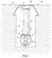
- FIG. 1 an embodiment of the device maneuver according to the invention installed in a manhole 104 surmounted by a pad 101 provided with a cover 102, for example made of cast iron, disposed at the ground level 100.
- the operating device is intended to control the opening or the closing of a tap 103 disposed on a buried pipe of a fluid transport network such as gas.
- the operating device according to the invention when it is not used, is placed in the rest position, compactly, inside the look 104 under the cover 102 so that the operating device is invisible, reducing the risk of theft and occupying no space in the premises served by the connection controlled by the tap 103.
- the cover 102 can be provided with a small opening key which can be placed under a dormant glass case in an aisle of the premises served by the connection controlled by tap 103.
- Such a key cover opening not shown in the drawing, is little bulky and given its small size, cannot be used as a tool and does not detract from the premises where it is placed.
- the operating device according to the invention is specifically designed to be easily accessible to anyone in case of emergency closing of the tap 103. To do this, the person just has to grab the key to open the cover 102 and after having removed this cover 102, ensures, by very simple deployment of the upper part of the operating device and controlling the valve 103 closing operation.
- Figure 1 shows the structure operating device telescopic in rest position, with a vertical outer tube 2 in rigid and stainless material surmounted at its upper part by a tray 1 for example in the form of a disc, on which is placed an arm of maneuver 16 which, in the rest position of Figure 1 is folded down parallel to the outer tube 2.
- the plate 1 further comprises a visual indicator 21 of the position of tap 103 (opening or closing).
- the outer tube 2 constitutes an upper tube inside which is located a lower tube 3 (see Figure 2) whose lower part is extended by a standard control tip 10, presenting by example a 30 mm square opening, which allows directly control the closing or opening of taps with heads square with the same dimension, but also allows the command to close or open all other types of valves subject to the use of an adapter such as element 12 which makes it possible for example to control a tap 103 with a head square of smaller dimensions.
- a strap 19 is disposed under the tap 103 and attached to removably, for example by retaining pins 20, to a plate or ring 18 which can be placed just above the end piece 10 at the lower part of the lower tube 3 ( Figures 1, 2 and 8, 9). Strap 19 serves safety element and prevents any untimely release of the nozzle 10 when the operating device is deployed to come in the working position of Figure 2.
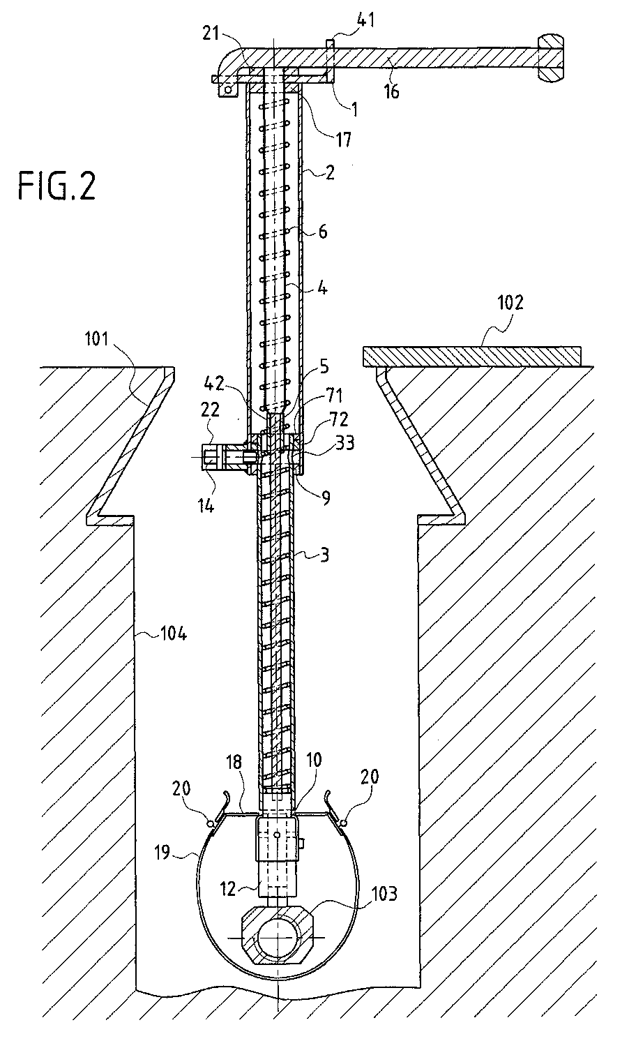
- Figure 2 shows, after opening the cover 102 of the tampon 101, the working position of the operating device according to the invention.
- the ring 9 ( Figures 2, 7 and 13) which is integral with the part bottom of the outer control tube 2 and has an opening 90 on its periphery, can be released relative to a stop pin 51 located at the bottom of the inner control tube 3 ( Figure 8).
- the control plate 1 fixed to the upper part of the upper tube 2 then came out of the manhole 104 and the maneuvering arm 16 previously retracted can be released by sliding in the receiving opening of the plate 1 in which it is engaged and retained by the bead 160, for then be tilted in a horizontal position and come to rest for example on the stirrup 41.
- the operating arm 16 could also be attached to plate 1 by a joint.
- a pin 55 ( Figure 4) allows to avoid untimely dissociation of the operating arm 16 by compared to plateau 1.
- the retractable operating arm 16 positioned horizontally on tray 1 allows an operator to easily close from tap 103, clockwise, through of the telescopic assembly comprising the upper tube 2, the tube lower 3, the control end piece 10 and the optional adapter such as item 12.
- the reopening of the tap is made impossible thanks to a system of non-return rings with pawls 71, 72 which constitutes a system for locking and securing the closing of the tap 103.
- a first non-return ring at pawls 71 is arranged at the upper part of the lower tube 3 and a second non-return ring with ratchets 72 is arranged at the part lower of the upper tube 2, above the ring 9 constituting a first non-secure locking means of the device in position folded.
- the first and second ratchet non-return rings 71, 72 may for example have the shape of the ring 70 shown on Figure 14 with four steps distributed crosswise. Rings 71, 72 serve as both guiding means during the sliding of the tube outer 2 relative to the inner tube 3, and locking means preventing counterclockwise rotation of the valve opening 103.
- the operating arm 16 can be returned to its position in Figure 1, the upper tube 2 is also returned to the position of Figure 1 by sliding around of the lower tube 3 against the action of the spring 6, until the plate 1 comes into abutment on the upper end of the lower tube 3, and the locking in the rest position is effected by rotation of a quarter turn allowing the locking guide ring 9 to again form a stop with the corresponding stop pin fixed on the lower tube 3, preventing any rise in the upper tube 2.
- the ring 9 and the rings 71, 72 can be fixed on the tubes respective for example using a solder or other connecting means equivalent ( Figure 8).
- the operating device allows reopening tap 103 by an authorized agent using a small key standard 15 (Figure 7) having for example a triangular profile, which comes to engage in a small horizontal tube 22 which is welded to the part bottom of the outer control tube 2 and which incorporates a lug of joining 14 comprising a triangular head 140, a flange 141, a thread 142 and a locking end 143 ( Figures 10 and 11) which can come and engage in one of the lights 33 provided in the part upper of lower tube 3.
- a small key standard 15 Figure 7 having for example a triangular profile, which comes to engage in a small horizontal tube 22 which is welded to the part bottom of the outer control tube 2 and which incorporates a lug of joining 14 comprising a triangular head 140, a flange 141, a thread 142 and a locking end 143 ( Figures 10 and 11) which can come and engage in one of the lights 33 provided in the part upper of lower tube 3.
- an authorized agent with a key 15 ( Figure 7) can then move the securing lug to allow securing in rotation of the lower 3 and upper 2 tubes thanks to the cooperation of the locking end 143 secured to the outer tube 2 and to a lumen 33 made in the lower tube 3.
- tubes 2 and 3 are separated by unscrewing the head screw triangular 14 using the key 15.
- the control plate 1 is then compressed on its axis 4, 5 against the action of the spring 6 until abutment against the upper end of the lower tube 3 and as a result of quarter-turn clockwise rotation, the operating device is again locked in an insecure manner, by the cooperation of the locking guide ring and stop pin 19 previously described.
- a valve 103 closing operation is then again rendered possible by anyone.
- the control plate 1 is made of a rigid material and stainless and can have the shape of a disc on which can be affixed, according to various procedures, operating instructions.
- a visual indicator of the direction of closing and opening of the tap 103 is materialized on the control plate 1 by a flange 21 provided with a reference 210, such as a diametral line or groove ( Figures 6 and 12).
- the collar 21 is integral with a central tube 4 of which at least one part, such that the lower part 42 has a hexagonal profile and allows the sliding of a rod 5 with hexagonal section whose part lower is secured to the control end piece 10, for example using a pin 53.
- the rod 5 and the tube 4 are integral in rotation so that the position of tap 103 can be materialized at any time whatever the position of the control plate 1.
- the lower part 42 of the tube 4 can be centered inside tube 3 using a washer centering 8 ( Figure 7).
- the operating device constitutes a device which, while always signaling the position of the tap at maneuver, authorizes only the closing action to any person and, thanks to the telescopic design with a non-return system lockable with key, reserves the reopening action to a qualified agent equipped a specific key 15 of small size.
- Figures 7A to 7C and 15 to 18 show various examples adapters for different valves, which can be attached to the control end piece 10 and fixed thereto for example by a screw 52 ( Figure 8).
- the adapter 11 ( Figures 7A and 15) is intended for taps with bar type head. It has a square head 110 engaged in the nozzle 10 and a base 111 in which a slot 112 is formed.
- the adapter 12 ( Figures 7B and 16) is intended for taps with small square head, for example 14 mm, and includes a square head 120 engaged in the nozzle 10 and a base 121 provided an opening 122 with a square section of smaller dimensions.
- the adapter 13 ( Figures 7C, 17 and 18) is intended for taps with lug and comprises a square head 130 engaged in the nozzle 10 and a collar 131 extended by a lower cylindrical part provided an opening 132 with an S profile.
- each adapter comprises a head adapted to the control nozzle 10.
Landscapes
- Engineering & Computer Science (AREA)
- General Engineering & Computer Science (AREA)
- Hydrology & Water Resources (AREA)
- Health & Medical Sciences (AREA)
- Public Health (AREA)
- Water Supply & Treatment (AREA)
- Life Sciences & Earth Sciences (AREA)
- Mechanical Engineering (AREA)
- Mechanically-Actuated Valves (AREA)
- Preventing Unauthorised Actuation Of Valves (AREA)
- Quick-Acting Or Multi-Walled Pipe Joints (AREA)
- Eye Examination Apparatus (AREA)
- Replacement Of Web Rolls (AREA)
- Magnetically Actuated Valves (AREA)
- Mechanical Pencils And Projecting And Retracting Systems Therefor, And Multi-System Writing Instruments (AREA)
Abstract
Description
- la Figure 1 est une vue en coupe d'un regard dans lequel est installé un dispositif de manoeuvre de robinet enterré conforme à l'invention, le dispositif étant en position escamotée,
- la Figure 2 est une vue en coupe analogue à la Figure 1, mais montrant un dispositif de manoeuvre en coupe axiale en position déployée,
- la Figure 3 est une vue en perspective du dispositif de manoeuvre de la Figure 1,
- les Figures 4 à 6 sont des vues respectivement en élévation, de dessous et de dessus du dispositif de manoeuvre de la Figure 3,
- la Figure 7 est une vue en coupe selon la ligne VII-VII de la Figure 6 montrant notamment l'utilisation d'une clé de déverrouillage.
- les Figures 7A, 7B, 7C montrent en élévation des exemples d'adaptateurs pouvant être utilisés avec le dispositif des Figures 3 à 7,
- la Figure 8 est une vue en coupe selon la ligne VIII-VIII de la Figure 6 montrant notamment l'utilisation d'une sangle,
- la Figure 9 est une vue de dessus d'une plaque de fixation d'une sangle,
- les Figures 10 et 11 sont des vues respectivement de côté et en bout d'un exemple d'ergot de solidarisation pouvant être manoeuvré par une clé de déverrouillage,
- la Figure 12 est une vue de dessus d'un exemple d'organe de repérage de la position d'ouverture ou de fermeture d'un robinet,
- la Figure 13 est une vue de dessus d'un exemple de bague guide de verrouillage utilisable dans le dispositif de manoeuvre selon l'invention,
- la Figure 14 est une vue en perspective d'un ensemble de rondelle anti-retour à cliquet utilisable dans le dispositif de manoeuvre selon l'invention,
- la Figure 15 est une vue en perspective d'un premier exemple d'adaptateur pouvant être monté sur un embout de commande du dispositif de manoeuvre selon l'invention,
- la Figure 16 est une vue de dessus d'un deuxième exemple d'adaptateur pouvant être monté sur un embout de commande du dispositif de manoeuvre selon l'invention, et
- les Figures 17 et 18 sont des vues en perspective sous deux angles différents d'un troisième exemple d'adaptateur pouvant être monté sur un embout de commande du dispositif de manoeuvre selon l'invention.
Claims (10)
- Dispositif de manoeuvre d'un robinet enterré (103) placé dans un regard (104) surmonté d'un tampon (101) muni d'un couvercle (102), le robinet (103) étant disposé sur un réseau de transport de fluide, caractérisé en ce que le dispositif de manoeuvre comprend :a) un embout de commande (10) raccordé de façon amovible audit robinet (103),b) un tube inférieur de commande (3) dont l'extrémité supérieure est située au niveau du tampon (101) sous le couvercle (102) et dont l'extrémité inférieure est solidaire de l'embout de commande (10),c) un tube supérieur de commande (2) monté coulissant de façon télescopique par rapport au tube inférieur de commande (3),d) un bras de manoeuvre (16) monté à la partie supérieure du tube supérieur de commande (2),e) des moyens de rappel élastique (6) permettant un déplacement vers le haut du tube supérieur de commande (2) par rapport au tube inférieur de commande (3),f) des premiers moyens (9, 51, 71, 72) de verrouillage et de guidage non sécurisés permettant d'une part un maintien du tube supérieur de commande (2) en position basse de façon concentrique au tube inférieur de commande (3) et d'autre part un déploiement sélectif du tube supérieur de commande (3) sous l'action des moyens de rappel élastique (6) et la manoeuvre simultanée des tubes inférieur et supérieur de commande (3, 2) et de l'embout de commande (10) dans le sens de la fermeture du robinet (103), etg) des seconds moyens de verrouillage sécurisés (14, 33, 71, 72) comportant des moyens de retenue anti-retour (71, 72) pour empêcher, après une action de fermeture, la manoeuvre du robinet (103) dans le sens de l'ouverture et des moyens (14, 33) pour autoriser une manoeuvre d'ouverture du robinet (103) à l'aide d'une clé de déverrouillage (15) introduite au niveau de la partie inférieure du tube supérieur de commande (2).
- Dispositif de manoeuvre selon la revendication 1, caractérisé en ce que les premiers moyens de verrouillage et de guidage non sécurisés et les seconds moyens de verrouillage sécurisés comprennent en commun des première et deuxième bagues anti-retour à cliquet (71, 72) interposées entre les tubes inférieur et supérieur de commande (3, 2) et respectivement solidaires de la partie supérieure du tube inférieur de commande (3) et de la partie inférieure du tube supérieur de commande (2).
- Dispositif de manoeuvre selon la revendication 1 ou 2, caractérisé en ce que les seconds moyens de verrouillage sécurisés comprennent un ergot de solidarisation (14) manoeuvrable par ladite clé de déverrouillage (15) pour traverser les tubes supérieur et inférieur de commande (3, 2) afin de solidariser ceux-ci de façon sélective lorsque le tube supérieur de commande (2) est en position déployée.
- Dispositif de manoeuvre selon l'une quelconque des revendications 1 à 3, caractérisé en ce que le tube supérieur de commande (2) est disposé à l'extérieur du tube inférieur de commande (3).
- Dispositif de manoeuvre selon l'une quelconque des revendications 1 à 4, caractérisé en ce qu'il comprend en outre un plateau (1) solidaire de la partie supérieure du tube supérieur de commande (2) et muni d'un indicateur (21) de repérage de la position ouverte ou fermée du robinet (103), l'indicateur de repérage (21) étant relié à l'embout de commande (10) par un ensemble de tiges télescopiques (4, 5) solidaires en rotation et disposées à l'intérieur des tubes inférieur et supérieur de commande (3, 2).
- Dispositif de manoeuvre selon l'une quelconque des revendications 1 à 5, caractérisé en ce qu'il comprend en outre une sangle de sécurité amovible (19) disposée sous le robinet (103) et reliée à l'embout de commande (10) pour empêcher une déconnexion de l'embout de commande (10) par rapport au robinet (103) lors du déploiement du tube supérieur de commande (2) sous l'action des moyens de rappel élastique (6).
- Dispositif de manoeuvre selon l'une quelconque des revendications 1 à 6, caractérisé en ce qu'il comprend un ou plusieurs éléments d'adaptation (11, 12, 13) interposés entre l'embout de commande (10) et le robinet (103).
- Dispositif de manoeuvre selon l'une quelconque des revendications 1 à 7, caractérisé en ce que le bras de manoeuvre (16) est monté sur un plateau (1) solidaire de la partie supérieure du tube supérieur de commande (2) de manière à pouvoir s'escamoter parallèlement audit tube supérieur de commande (2).
- Dispositif de manoeuvre selon l'une quelconque des revendications 1 à 8, caractérisé en ce que les premiers moyens de verrouillage et de guidage non sécurisés comprennent une bague (9) munie d'une ouverture sur une portion de sa périphérie et située à la base du tube supérieur de commande (2) pour assurer par une rotation relative des tubes supérieur et inférieur de commande (2, 3) l'un par rapport à l'autre un verrouillage sur un pion d'arrêt (51) situé sur la base du tube inférieur de commande (3) lorsque le tube supérieur de commande (2) est en position basse, contre l'action des moyens de rappel élastique (6).
- Dispositif de manoeuvre selon l'une quelconque des revendications 1 à 9, caractérisé en ce qu'il est appliqué à la commande de robinets de gaz.
Applications Claiming Priority (2)
| Application Number | Priority Date | Filing Date | Title |
|---|---|---|---|
| FR0107837 | 2001-06-15 | ||
| FR0107837A FR2826090B1 (fr) | 2001-06-15 | 2001-06-15 | Dispositif de manoeuvre d'un robinet enterre |
Publications (2)
| Publication Number | Publication Date |
|---|---|
| EP1267110A1 true EP1267110A1 (fr) | 2002-12-18 |
| EP1267110B1 EP1267110B1 (fr) | 2005-08-31 |
Family
ID=8864344
Family Applications (1)
| Application Number | Title | Priority Date | Filing Date |
|---|---|---|---|
| EP02291464A Expired - Lifetime EP1267110B1 (fr) | 2001-06-15 | 2002-06-12 | Dispositif de manoeuvre d'un robinet enterre |
Country Status (4)
| Country | Link |
|---|---|
| EP (1) | EP1267110B1 (fr) |
| AT (1) | ATE303540T1 (fr) |
| DE (1) | DE60205813T2 (fr) |
| FR (1) | FR2826090B1 (fr) |
Cited By (4)
| Publication number | Priority date | Publication date | Assignee | Title |
|---|---|---|---|---|
| DE102006015802A1 (de) * | 2006-04-03 | 2007-10-04 | Schütz, Norbert | Rohrverbindung |
| CN107503400A (zh) * | 2017-09-30 | 2017-12-22 | 镇江玄润消防器材有限公司 | 地埋式消防栓 |
| CN108798581A (zh) * | 2018-05-29 | 2018-11-13 | 中国石油集团川庆钻探工程有限公司长庆钻井总公司 | 一种封井器链条式手动锁紧装置及其使用方法 |
| CN112482501A (zh) * | 2020-11-05 | 2021-03-12 | 周圆鹤 | 一种消防用室外消防栓 |
Citations (5)
| Publication number | Priority date | Publication date | Assignee | Title |
|---|---|---|---|---|
| DE2557271A1 (de) * | 1975-12-19 | 1977-06-30 | Indusha Ind Und Handelsbedarf | Stufenlos laengeneinstellbares stellgestaenge, sogenannte schluesselstange, fuer unterpflaster-ventile |
| GB2033517A (en) * | 1978-11-03 | 1980-05-21 | Lynn W T | Adjustable length telescopic sleeves |
| DE3103264A1 (de) * | 1981-01-31 | 1982-08-26 | Johann 8802 Weihenzell Stoll | Strassenschieber |
| US4702275A (en) * | 1986-05-12 | 1987-10-27 | Amsted Industries Incorporated | Post assembly for a buried valve |
| DE3940378A1 (de) * | 1988-12-07 | 1990-06-13 | Balay Sa | Antriebsmechanismus fuer steuerungen von eingebauten geraeten |
-
2001
- 2001-06-15 FR FR0107837A patent/FR2826090B1/fr not_active Expired - Fee Related
-
2002
- 2002-06-12 EP EP02291464A patent/EP1267110B1/fr not_active Expired - Lifetime
- 2002-06-12 AT AT02291464T patent/ATE303540T1/de not_active IP Right Cessation
- 2002-06-12 DE DE60205813T patent/DE60205813T2/de not_active Expired - Lifetime
Patent Citations (5)
| Publication number | Priority date | Publication date | Assignee | Title |
|---|---|---|---|---|
| DE2557271A1 (de) * | 1975-12-19 | 1977-06-30 | Indusha Ind Und Handelsbedarf | Stufenlos laengeneinstellbares stellgestaenge, sogenannte schluesselstange, fuer unterpflaster-ventile |
| GB2033517A (en) * | 1978-11-03 | 1980-05-21 | Lynn W T | Adjustable length telescopic sleeves |
| DE3103264A1 (de) * | 1981-01-31 | 1982-08-26 | Johann 8802 Weihenzell Stoll | Strassenschieber |
| US4702275A (en) * | 1986-05-12 | 1987-10-27 | Amsted Industries Incorporated | Post assembly for a buried valve |
| DE3940378A1 (de) * | 1988-12-07 | 1990-06-13 | Balay Sa | Antriebsmechanismus fuer steuerungen von eingebauten geraeten |
Cited By (6)
| Publication number | Priority date | Publication date | Assignee | Title |
|---|---|---|---|---|
| DE102006015802A1 (de) * | 2006-04-03 | 2007-10-04 | Schütz, Norbert | Rohrverbindung |
| DE102006015802B4 (de) * | 2006-04-03 | 2012-05-03 | Norbert Schütz | Rohrverbindung |
| CN107503400A (zh) * | 2017-09-30 | 2017-12-22 | 镇江玄润消防器材有限公司 | 地埋式消防栓 |
| CN108798581A (zh) * | 2018-05-29 | 2018-11-13 | 中国石油集团川庆钻探工程有限公司长庆钻井总公司 | 一种封井器链条式手动锁紧装置及其使用方法 |
| CN108798581B (zh) * | 2018-05-29 | 2024-03-15 | 中国石油天然气集团有限公司 | 一种封井器链条式手动锁紧装置及其使用方法 |
| CN112482501A (zh) * | 2020-11-05 | 2021-03-12 | 周圆鹤 | 一种消防用室外消防栓 |
Also Published As
| Publication number | Publication date |
|---|---|
| EP1267110B1 (fr) | 2005-08-31 |
| DE60205813T2 (de) | 2006-06-22 |
| FR2826090A1 (fr) | 2002-12-20 |
| ATE303540T1 (de) | 2005-09-15 |
| FR2826090B1 (fr) | 2003-09-19 |
| DE60205813D1 (de) | 2005-10-06 |
Similar Documents
| Publication | Publication Date | Title |
|---|---|---|
| EP0803268B1 (fr) | Poulie à flasque pivotant et à bloqueur intégré | |
| EP0581693B1 (fr) | Mousqueton à galet de verrouillage automatique | |
| EP2371713B1 (fr) | Système d'axe pour ensemble de liaison d'un mât-réacteur sous une voilure d'aéronef | |
| EP1710456B1 (fr) | Mousqueton à verrouillage automatique | |
| FR2836964A1 (fr) | Mousqueton equipe d'une bague de verrouillage a patte de separation | |
| FR2930317A1 (fr) | Ensemble comprenant un robinet et un chapeau de protection, bouteille comprenant un tel ensemble | |
| FR3030284A1 (fr) | Systeme d'arrimage de securite, mousqueton utilisable pour un tel systeme et ensemble d'arrimage comprenant un tel systeme | |
| EP3693653A1 (fr) | Dispositif de fourniture de fluide sous pression et ensemble de stockage(s) de fluide sous pression comprenant un tel dispositif | |
| EP1267110B1 (fr) | Dispositif de manoeuvre d'un robinet enterre | |
| EP3693654B1 (fr) | Dispositif de fourniture de fluide sous pression et ensemble de stockage(s) de fluide sous pression comprenant un tel dispositif | |
| FR2696706A1 (fr) | Issue de secours à double configuration pour l'évacuation terrestre et après amerrissage d'une cabine d'aéronef. | |
| CA1145174A (fr) | Dispositif de securite de largage d'une charge suspendue a un aeronef pour son transport, et charge equipee d'un tel dispositif | |
| EP1302607A1 (fr) | Appareil de levage pour la mise en place de plaques au plafond | |
| EP2611578B1 (fr) | Procédé de pivotement à distance et outil de mise en oeuvre | |
| EP0185568A1 (fr) | Raccord à baionnette de télémanipulateur comportant une sécurité contre un déverrouillage accidentel | |
| FR2544007A1 (fr) | Dispositif de manoeuvre d'un element de carrosserie pivotant | |
| EP0555129B1 (fr) | Trappe à fermeture automatique | |
| FR2724687A1 (fr) | Dispositif de fermeture de surete, en particulier pour capot-regard | |
| FR2836946A1 (fr) | Dispositif de double verrouillage, notamment pour portillon ou analogue de barriere de protection d'une piscine | |
| FR2772455A1 (fr) | Dispositif adaptable en amont d'une vanne ou analogue de dechargement de liquides, a fonctions multiples notamment de verrouillage et controle | |
| EP3656628A1 (fr) | Voiture à deux étages de véhicule ferroviaire, comprenant une sortie d'évacuation d'urgence | |
| FR2892752A1 (fr) | Dispositif de verrouillage securise d'un tampon ou couvercle a un cadre, notamment de regard de chaussee | |
| FR3094279A1 (fr) | Dispositif d’attelage de sécurité pour véhicule | |
| FR2817902A1 (fr) | Dispositif de condamnation securisee de l'acces a une echelle a crinoline | |
| EP0424288B1 (fr) | Dispositif de verrouillage d'un ouvrant et huisserie incorporant un tel dispositif |
Legal Events
| Date | Code | Title | Description |
|---|---|---|---|
| PUAI | Public reference made under article 153(3) epc to a published international application that has entered the european phase |
Free format text: ORIGINAL CODE: 0009012 |
|
| AK | Designated contracting states |
Kind code of ref document: A1 Designated state(s): AT BE CH CY DE DK ES FI FR GB GR IE IT LI LU MC NL PT SE TR |
|
| AX | Request for extension of the european patent |
Free format text: AL;LT;LV;MK;RO;SI |
|
| 17P | Request for examination filed |
Effective date: 20030606 |
|
| AKX | Designation fees paid |
Designated state(s): AT BE CH CY DE DK ES FI FR GB GR IE IT LI LU MC NL PT SE TR |
|
| GRAP | Despatch of communication of intention to grant a patent |
Free format text: ORIGINAL CODE: EPIDOSNIGR1 |
|
| GRAS | Grant fee paid |
Free format text: ORIGINAL CODE: EPIDOSNIGR3 |
|
| GRAA | (expected) grant |
Free format text: ORIGINAL CODE: 0009210 |
|
| AK | Designated contracting states |
Kind code of ref document: B1 Designated state(s): AT BE CH CY DE DK ES FI FR GB GR IE IT LI LU MC NL PT SE TR |
|
| PG25 | Lapsed in a contracting state [announced via postgrant information from national office to epo] |
Ref country code: AT Free format text: LAPSE BECAUSE OF FAILURE TO SUBMIT A TRANSLATION OF THE DESCRIPTION OR TO PAY THE FEE WITHIN THE PRESCRIBED TIME-LIMIT Effective date: 20050831 Ref country code: FI Free format text: LAPSE BECAUSE OF FAILURE TO SUBMIT A TRANSLATION OF THE DESCRIPTION OR TO PAY THE FEE WITHIN THE PRESCRIBED TIME-LIMIT Effective date: 20050831 Ref country code: GB Free format text: LAPSE BECAUSE OF FAILURE TO SUBMIT A TRANSLATION OF THE DESCRIPTION OR TO PAY THE FEE WITHIN THE PRESCRIBED TIME-LIMIT Effective date: 20050831 Ref country code: IE Free format text: LAPSE BECAUSE OF FAILURE TO SUBMIT A TRANSLATION OF THE DESCRIPTION OR TO PAY THE FEE WITHIN THE PRESCRIBED TIME-LIMIT Effective date: 20050831 Ref country code: NL Free format text: LAPSE BECAUSE OF FAILURE TO SUBMIT A TRANSLATION OF THE DESCRIPTION OR TO PAY THE FEE WITHIN THE PRESCRIBED TIME-LIMIT Effective date: 20050831 |
|
| REG | Reference to a national code |
Ref country code: GB Ref legal event code: FG4D Free format text: NOT ENGLISH Ref country code: CH Ref legal event code: EP |
|
| REG | Reference to a national code |
Ref country code: IE Ref legal event code: FG4D Free format text: LANGUAGE OF EP DOCUMENT: FRENCH |
|
| REF | Corresponds to: |
Ref document number: 60205813 Country of ref document: DE Date of ref document: 20051006 Kind code of ref document: P |
|
| PG25 | Lapsed in a contracting state [announced via postgrant information from national office to epo] |
Ref country code: SE Free format text: LAPSE BECAUSE OF FAILURE TO SUBMIT A TRANSLATION OF THE DESCRIPTION OR TO PAY THE FEE WITHIN THE PRESCRIBED TIME-LIMIT Effective date: 20051130 Ref country code: GR Free format text: LAPSE BECAUSE OF FAILURE TO SUBMIT A TRANSLATION OF THE DESCRIPTION OR TO PAY THE FEE WITHIN THE PRESCRIBED TIME-LIMIT Effective date: 20051130 Ref country code: DK Free format text: LAPSE BECAUSE OF FAILURE TO SUBMIT A TRANSLATION OF THE DESCRIPTION OR TO PAY THE FEE WITHIN THE PRESCRIBED TIME-LIMIT Effective date: 20051130 |
|
| PG25 | Lapsed in a contracting state [announced via postgrant information from national office to epo] |
Ref country code: PT Free format text: LAPSE BECAUSE OF FAILURE TO SUBMIT A TRANSLATION OF THE DESCRIPTION OR TO PAY THE FEE WITHIN THE PRESCRIBED TIME-LIMIT Effective date: 20060222 |
|
| NLV1 | Nl: lapsed or annulled due to failure to fulfill the requirements of art. 29p and 29m of the patents act | ||
| REG | Reference to a national code |
Ref country code: IE Ref legal event code: FD4D |
|
| GBV | Gb: ep patent (uk) treated as always having been void in accordance with gb section 77(7)/1977 [no translation filed] |
Effective date: 20050831 |
|
| PG25 | Lapsed in a contracting state [announced via postgrant information from national office to epo] |
Ref country code: CH Free format text: LAPSE BECAUSE OF NON-PAYMENT OF DUE FEES Effective date: 20060630 Ref country code: LI Free format text: LAPSE BECAUSE OF NON-PAYMENT OF DUE FEES Effective date: 20060630 |
|
| PLBE | No opposition filed within time limit |
Free format text: ORIGINAL CODE: 0009261 |
|
| STAA | Information on the status of an ep patent application or granted ep patent |
Free format text: STATUS: NO OPPOSITION FILED WITHIN TIME LIMIT |
|
| 26N | No opposition filed |
Effective date: 20060601 |
|
| REG | Reference to a national code |
Ref country code: CH Ref legal event code: PL |
|
| PG25 | Lapsed in a contracting state [announced via postgrant information from national office to epo] |
Ref country code: TR Free format text: LAPSE BECAUSE OF FAILURE TO SUBMIT A TRANSLATION OF THE DESCRIPTION OR TO PAY THE FEE WITHIN THE PRESCRIBED TIME-LIMIT Effective date: 20050831 |
|
| PG25 | Lapsed in a contracting state [announced via postgrant information from national office to epo] |
Ref country code: CY Free format text: LAPSE BECAUSE OF FAILURE TO SUBMIT A TRANSLATION OF THE DESCRIPTION OR TO PAY THE FEE WITHIN THE PRESCRIBED TIME-LIMIT Effective date: 20050831 |
|
| PG25 | Lapsed in a contracting state [announced via postgrant information from national office to epo] |
Ref country code: ES Free format text: LAPSE BECAUSE OF NON-PAYMENT OF DUE FEES Effective date: 20060630 |
|
| REG | Reference to a national code |
Ref country code: FR Ref legal event code: CA Ref country code: FR Ref legal event code: CJ Ref country code: FR Ref legal event code: CD |
|
| REG | Reference to a national code |
Ref country code: DE Ref legal event code: R082 Ref document number: 60205813 Country of ref document: DE Representative=s name: CBDL PATENTANWAELTE, DE |
|
| REG | Reference to a national code |
Ref country code: DE Ref legal event code: R082 Ref document number: 60205813 Country of ref document: DE Representative=s name: CBDL PATENTANWAELTE, DE Effective date: 20111028 Ref country code: DE Ref legal event code: R081 Ref document number: 60205813 Country of ref document: DE Owner name: GDF SUEZ S.A., FR Free format text: FORMER OWNER: GAZ DE FRANCE, PARIS, FR Effective date: 20111028 |
|
| REG | Reference to a national code |
Ref country code: FR Ref legal event code: PLFP Year of fee payment: 15 |
|
| PGFP | Annual fee paid to national office [announced via postgrant information from national office to epo] |
Ref country code: LU Payment date: 20160525 Year of fee payment: 15 |
|
| PGFP | Annual fee paid to national office [announced via postgrant information from national office to epo] |
Ref country code: MC Payment date: 20160525 Year of fee payment: 15 Ref country code: DE Payment date: 20160524 Year of fee payment: 15 |
|
| PGFP | Annual fee paid to national office [announced via postgrant information from national office to epo] |
Ref country code: BE Payment date: 20160525 Year of fee payment: 15 Ref country code: IT Payment date: 20160525 Year of fee payment: 15 Ref country code: FR Payment date: 20160526 Year of fee payment: 15 |
|
| REG | Reference to a national code |
Ref country code: DE Ref legal event code: R119 Ref document number: 60205813 Country of ref document: DE |
|
| PG25 | Lapsed in a contracting state [announced via postgrant information from national office to epo] |
Ref country code: MC Free format text: LAPSE BECAUSE OF NON-PAYMENT OF DUE FEES Effective date: 20170630 |
|
| REG | Reference to a national code |
Ref country code: FR Ref legal event code: ST Effective date: 20180228 |
|
| PG25 | Lapsed in a contracting state [announced via postgrant information from national office to epo] |
Ref country code: DE Free format text: LAPSE BECAUSE OF NON-PAYMENT OF DUE FEES Effective date: 20180103 Ref country code: LU Free format text: LAPSE BECAUSE OF NON-PAYMENT OF DUE FEES Effective date: 20170612 |
|
| PG25 | Lapsed in a contracting state [announced via postgrant information from national office to epo] |
Ref country code: IT Free format text: LAPSE BECAUSE OF NON-PAYMENT OF DUE FEES Effective date: 20170612 Ref country code: FR Free format text: LAPSE BECAUSE OF NON-PAYMENT OF DUE FEES Effective date: 20170630 |
|
| REG | Reference to a national code |
Ref country code: BE Ref legal event code: MM Effective date: 20170630 |
|
| PG25 | Lapsed in a contracting state [announced via postgrant information from national office to epo] |
Ref country code: BE Free format text: LAPSE BECAUSE OF NON-PAYMENT OF DUE FEES Effective date: 20170630 |