EP1267123A2 - Vorrichtung zum Austragen von Holzpellets aus einem Lagerraum - Google Patents
Vorrichtung zum Austragen von Holzpellets aus einem Lagerraum Download PDFInfo
- Publication number
- EP1267123A2 EP1267123A2 EP02450134A EP02450134A EP1267123A2 EP 1267123 A2 EP1267123 A2 EP 1267123A2 EP 02450134 A EP02450134 A EP 02450134A EP 02450134 A EP02450134 A EP 02450134A EP 1267123 A2 EP1267123 A2 EP 1267123A2
- Authority
- EP
- European Patent Office
- Prior art keywords
- discharge screw
- vibrating plate
- sliding wall
- discharge
- wood pellets
- Prior art date
- Legal status (The legal status is an assumption and is not a legal conclusion. Google has not performed a legal analysis and makes no representation as to the accuracy of the status listed.)
- Granted
Links
- 239000008188 pellet Substances 0.000 title claims abstract description 20
- 239000002023 wood Substances 0.000 title claims abstract description 19
- 238000007599 discharging Methods 0.000 claims abstract description 4
- 238000010276 construction Methods 0.000 abstract 1
- 239000000446 fuel Substances 0.000 description 4
- 238000006073 displacement reaction Methods 0.000 description 2
- 239000002184 metal Substances 0.000 description 2
- TVEXGJYMHHTVKP-UHFFFAOYSA-N 6-oxabicyclo[3.2.1]oct-3-en-7-one Chemical compound C1C2C(=O)OC1C=CC2 TVEXGJYMHHTVKP-UHFFFAOYSA-N 0.000 description 1
- 238000005452 bending Methods 0.000 description 1
- 238000005192 partition Methods 0.000 description 1
Images

Classifications
-
- B—PERFORMING OPERATIONS; TRANSPORTING
- B65—CONVEYING; PACKING; STORING; HANDLING THIN OR FILAMENTARY MATERIAL
- B65G—TRANSPORT OR STORAGE DEVICES, e.g. CONVEYORS FOR LOADING OR TIPPING, SHOP CONVEYOR SYSTEMS OR PNEUMATIC TUBE CONVEYORS
- B65G65/00—Loading or unloading
- B65G65/30—Methods or devices for filling or emptying bunkers, hoppers, tanks, or like containers, of interest apart from their use in particular chemical or physical processes or their application in particular machines, e.g. not covered by a single other subclass
- B65G65/34—Emptying devices
- B65G65/40—Devices for emptying otherwise than from the top
- B65G65/44—Devices for emptying otherwise than from the top using reciprocating conveyors, e.g. jigging conveyors
-
- B—PERFORMING OPERATIONS; TRANSPORTING
- B65—CONVEYING; PACKING; STORING; HANDLING THIN OR FILAMENTARY MATERIAL
- B65D—CONTAINERS FOR STORAGE OR TRANSPORT OF ARTICLES OR MATERIALS, e.g. BAGS, BARRELS, BOTTLES, BOXES, CANS, CARTONS, CRATES, DRUMS, JARS, TANKS, HOPPERS, FORWARDING CONTAINERS; ACCESSORIES, CLOSURES, OR FITTINGS THEREFOR; PACKAGING ELEMENTS; PACKAGES
- B65D88/00—Large containers
- B65D88/54—Large containers characterised by means facilitating filling or emptying
- B65D88/64—Large containers characterised by means facilitating filling or emptying preventing bridge formation
-
- F—MECHANICAL ENGINEERING; LIGHTING; HEATING; WEAPONS; BLASTING
- F23—COMBUSTION APPARATUS; COMBUSTION PROCESSES
- F23K—FEEDING FUEL TO COMBUSTION APPARATUS
- F23K3/00—Feeding or distributing of lump or pulverulent fuel to combustion apparatus
-
- F—MECHANICAL ENGINEERING; LIGHTING; HEATING; WEAPONS; BLASTING
- F23—COMBUSTION APPARATUS; COMBUSTION PROCESSES
- F23K—FEEDING FUEL TO COMBUSTION APPARATUS
- F23K2203/00—Feeding arrangements
- F23K2203/10—Supply line fittings
- F23K2203/103—Storage devices
-
- F—MECHANICAL ENGINEERING; LIGHTING; HEATING; WEAPONS; BLASTING
- F23—COMBUSTION APPARATUS; COMBUSTION PROCESSES
- F23K—FEEDING FUEL TO COMBUSTION APPARATUS
- F23K2203/00—Feeding arrangements
- F23K2203/20—Feeding/conveying devices
- F23K2203/202—Feeding/conveying devices using screws
Definitions
- the invention relates to a device for discharging Wood pellets from a storage room with one at a discharge opening between connectable inclined bottom sections, receiving a discharge screw Housing that has a sliding wall sloping towards the discharge screw.
- Discharge screws are used to discharge wood pellets from storage rooms used, which are stored in trough-like housings. Because the housing in the area of between inclined floor sections of the respective Storage space resulting discharge opening is provided, slide Wood pellets along the inclined bottom sections to the discharge opening of the Storage room and via a sliding wall of the housing to the discharge screw then conveyed out of the housing at the end using the discharge screw become.
- these known discharge devices cannot be uniform adapted to the particular fuel requirement of a boiler Ensure discharge of wood pellets.
- the invention is therefore based on the object of a device for Discharge of wood pellets from a storage room of the type described above with simple constructive means so that a trouble-free, adapted to the respective fuel requirement, the export of wood pellets the storage room can be guaranteed.
- the invention solves the problem in that the sliding wall a recess parallel to the discharge screw for receiving a transverse to Discharge screw along the sliding wall of the vibrating plate forms, which can be driven by an eccentric drive from the shaft of the discharge screw is.
- One opposite the upper boundary wall of the inlet channel in Direction of conveyance diverging lower section of the vibrating plate can be in simply by angling the vibrating plate accordingly reach when the lower section of the vibrating plate is opposite the subsequent one
- the sheet metal section is inclined downwards.
- the eccentric drive for driving the vibrating plate can vary be carried out constructively. Particularly simple design relationships arise, however, if this eccentric drive from one on the front the worm shaft eccentrically arranged crank pin for one on the vibrating plate articulated connecting lever exists. In this case, only needs the worm shaft to be drilled eccentrically on the end face around the crank pin to use for the connecting lever, which is thus a connecting rod for the Vibratory plate drive becomes effective.
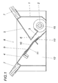
- the discharge device from a housing 1, which receives a discharge screw 2.
- This Discharge screw 2 is preceded by an inlet channel 3 within the housing 1, which is delimited on the underside by a sliding wall 4.
- This sliding wall 4 forms with an opposite, also inclined wall 5 a funnel-like inlet section of the housing 1, which in the inlet channel 3rd merges with the boundary wall opposite the sliding wall 4 with 6 is designated. Since the walls 4 and 5 each inclined floor sections 7 one continue storage space, not shown, closes the funnel-shaped Inlet part of the housing 1 between the walls 4 and 5 directly to the Discharge opening 8 of the storage room between the bottom sections 7.
- the sliding wall 4 forms a recess 9, which is parallel to the discharge screw 2 extends and receives a vibrating plate 10 which in slot guides 11 of the end walls 12 of the housing 1 transverse to the discharge screw 2 along the sliding wall 4 is slidably held.
- a vibrating plate 10 which in slot guides 11 of the end walls 12 of the housing 1 transverse to the discharge screw 2 along the sliding wall 4 is slidably held.
- partitions between the end walls 12 corresponding slot guides 11 may be provided. Since the vibrating plate 10 forms a lower edge-parallel section 13, which is opposite to the subsequent The sheet metal section is angled downward, and the slot guides 11 have a course adapted to the angled shape of the vibrating plate 10, is when the vibrating plate 10 moves along the slot guides 11 an additional displacement of the vibrating plate 10 transversely to the sliding wall 4 reached.
- the drive of the vibrating plate 10 takes place according to FIG. 2 via a Eccentric drive 14, which according to the illustrated embodiment from a on the end face of the worm shaft 15 eccentrically arranged crank pin 16 exists on which a connecting lever 17 is mounted as a connecting rod.
- This Connection lever 17 is articulated on the vibrating plate 10 via an axis 18, so that with each rotation of the worm shaft 15 a back and forth Swinging movement of the vibrating plate 10 is connected.
- the sliding wall 4 in Area of the inlet channel 3 forms the vibrating plate 10 in the area of the inlet duct 3 with the lower section 13 a slide, which is the further conveyance of the feed channel 3 Wood pellet to discharge screw 2 supports because of this section 13 with the boundary wall 6 of the inlet channel 3 against the discharge screw 2 diverges.
- Wood pellets are made according to the drive of the discharge screw 2 through the vibrating plate 10 into the inlet channel 3 and from there to the discharge screw 2 promoted, due to the dependence of the funding movement of Vibrating plates 10 from the rotational speed of the discharge screw 2
- Amount of wood pellets fed via the vibrating plate 10 of the discharge screw 2 corresponds to the delivery rate of the discharge screw 2, so that with a such a discharge device advantageous to the respective fuel requirement adapted discharge of the wood pellets from the storage room is guaranteed.
Landscapes
- Engineering & Computer Science (AREA)
- Mechanical Engineering (AREA)
- Chemical & Material Sciences (AREA)
- Combustion & Propulsion (AREA)
- General Engineering & Computer Science (AREA)
- Filling Or Emptying Of Bunkers, Hoppers, And Tanks (AREA)
- Jigging Conveyors (AREA)
Abstract
Description
- Fig. 1
- eine erfindungsgemäße Vorrichtung zum Austragen von Holzpellets aus einem Lagerraum in einem vereinfachten Querschnitt und
- Fig. 2
- diese Vorrichtung in einer stirnseitigen Ansicht.
Claims (5)
- Vorrichtung zum Austragen von Holzpellets aus einem Lagerraum mit einem an eine Austragsöffnung (8) zwischen geneigten Bodenabschnitten (7) anschließbaren, eine Austragschnecke (2) aufnehmenden Gehäuse (1), das eine zur Austragschnecke (2) abfallende Gleitwand (4)aufweist, dadurch gekennzeichnet, daß die Gleitwand (4) eine zur Austragschnecke (2) parallele Ausnehmung (9) zur Aufnahme eines quer zur Austragschnecke (2) entlang der Gleitwand (4) verschiebbar gelagerten Rüttelbleches (10) bildet, das über einen Exzentertrieb (14) von der Welle (15) der Austragschnecke (2) antreibbar ist.
- Vorrichtung nach Anspruch 1, dadurch gekennzeichnet, daß das Rüttelblech (10) mit einem unteren randparallelen Abschnitt (13) in einen nach unten durch die Gleitwand (4) begrenzten Zulaufkanal (3) zur Austragschnecke (2) ragt, dessen der Gleitwand (4) gegenüberliegende Begrenzungswand (6) mit dem unteren Abschnitt (13) des Rüttelbleches (10) gegen die Austragschnecke (2) hin divergiert.
- Vorrichtung nach Anspruch 2, dadurch gekennzeichnet, daß der untere Abschnitt (13) des Rüttelbleches (10) gegenüber dem anschließenden Blechabschnitt abwärts abgewinkelt ist.
- Vorrichtung nach Anspruch 3, dadurch gekennzeichnet, daß das Rüttelblech (10) in Schlitzführungen (11) mit einem der abgewinkelten Form des Rüttelbleches (10) entsprechenden Verlauf verschiebbar geführt ist.
- Vorrichtung nach einem der Ansprüche 1 bis 4, dadurch gekennzeichnet, daß der Exzentertrieb (14) aus einem auf der Stirnseite der Schneckenwelle (15) exzentrisch angeordneten Kurbelzapfen (16) für einen am Rüttelblech (10) angelenkten Verbindungshebel (17) besteht.
Applications Claiming Priority (2)
| Application Number | Priority Date | Filing Date | Title |
|---|---|---|---|
| AT0046901U AT5370U1 (de) | 2001-06-12 | 2001-06-12 | Vorrichtung zum austragen von holzpellets aus einem lagerraum |
| AT46901U | 2001-06-12 |
Publications (3)
| Publication Number | Publication Date |
|---|---|
| EP1267123A2 true EP1267123A2 (de) | 2002-12-18 |
| EP1267123A3 EP1267123A3 (de) | 2003-03-26 |
| EP1267123B1 EP1267123B1 (de) | 2009-09-09 |
Family
ID=3491426
Family Applications (1)
| Application Number | Title | Priority Date | Filing Date |
|---|---|---|---|
| EP02450134A Expired - Lifetime EP1267123B1 (de) | 2001-06-12 | 2002-06-07 | Vorrichtung zum Austragen von Holzpellets aus einem Lagerraum |
Country Status (3)
| Country | Link |
|---|---|
| EP (1) | EP1267123B1 (de) |
| AT (2) | AT5370U1 (de) |
| DE (1) | DE50213829D1 (de) |
Cited By (3)
| Publication number | Priority date | Publication date | Assignee | Title |
|---|---|---|---|---|
| WO2004078625A1 (en) * | 2003-03-03 | 2004-09-16 | Nordstroem Kjell | Feeding means for a fuel storage |
| WO2007123480A1 (en) * | 2006-04-21 | 2007-11-01 | Lidani Ab | Device at a container for combustible goods arranged to be transported by a conveyor from the container to subsequent management |
| AT511375A1 (de) * | 2011-04-21 | 2012-11-15 | Marc Mag Simbuerger | Abscheid- und dosiertechnik |
Family Cites Families (4)
| Publication number | Priority date | Publication date | Assignee | Title |
|---|---|---|---|---|
| US2560480A (en) * | 1947-05-13 | 1951-07-10 | John B Rogers | Hopper shaker plate and comb assembly |
| CH256762A (de) * | 1947-06-28 | 1948-08-31 | Rueegsegger Walter | Beschickungsvorrichtung für mit festen Brennstoffen betriebene Feuerungsanlagen. |
| DE3007490C2 (de) * | 1980-02-28 | 1983-04-21 | Hoopman Onderzoek en Ontwikkeling B.V., Aalten | Austrag- und Dosiervorrichtung für insbesondere klumpenbildendes Futter |
| AT378356B (de) * | 1983-05-25 | 1985-07-25 | Oetiker Hans Maschinen | Einrichtung zur vermeidung von ueberlastungen von foerdereinrichtungen |
-
2001
- 2001-06-12 AT AT0046901U patent/AT5370U1/de not_active IP Right Cessation
-
2002
- 2002-06-07 AT AT02450134T patent/ATE442552T1/de active
- 2002-06-07 EP EP02450134A patent/EP1267123B1/de not_active Expired - Lifetime
- 2002-06-07 DE DE50213829T patent/DE50213829D1/de not_active Expired - Lifetime
Cited By (3)
| Publication number | Priority date | Publication date | Assignee | Title |
|---|---|---|---|---|
| WO2004078625A1 (en) * | 2003-03-03 | 2004-09-16 | Nordstroem Kjell | Feeding means for a fuel storage |
| WO2007123480A1 (en) * | 2006-04-21 | 2007-11-01 | Lidani Ab | Device at a container for combustible goods arranged to be transported by a conveyor from the container to subsequent management |
| AT511375A1 (de) * | 2011-04-21 | 2012-11-15 | Marc Mag Simbuerger | Abscheid- und dosiertechnik |
Also Published As
| Publication number | Publication date |
|---|---|
| AT5370U1 (de) | 2002-06-25 |
| ATE442552T1 (de) | 2009-09-15 |
| EP1267123B1 (de) | 2009-09-09 |
| EP1267123A3 (de) | 2003-03-26 |
| DE50213829D1 (de) | 2009-10-22 |
Similar Documents
| Publication | Publication Date | Title |
|---|---|---|
| DE2649785A1 (de) | Pumpe mit mehreren hin- und hergehenden kolben | |
| DE102005040971B4 (de) | Spiralverdichter mit Funktion zum Verhindern eines Schmierölverlustes | |
| EP1267123B1 (de) | Vorrichtung zum Austragen von Holzpellets aus einem Lagerraum | |
| EP2942436A1 (de) | Rechen mit räumer | |
| EP1454066B1 (de) | Tauchpumpenanordnung mit einem schwimmerschalter | |
| DE3528963C2 (de) | ||
| DE2240685A1 (de) | Messpumpe | |
| EP0563700A1 (de) | Vorrichtung zum Regeln des Luftdurchsatzes in einem Luftkanal | |
| DE1938650C3 (de) | Presse zum Verdichten von trockenem, faserigem Gut | |
| DE3141965C2 (de) | ||
| DE2232982A1 (de) | Vorrichtung zum abschneiden und formen von axialen anschlussleitern elektrischer schaltungselemente | |
| DE202008003260U1 (de) | Maschine zur Behandlung von Besteck | |
| DE1553055A1 (de) | Fluegelradpumpe fuer Fluessigkeiten | |
| DE69107118T2 (de) | Vorrichtung zur Abgabe von Teig. | |
| DE3409840C2 (de) | ||
| DE855978C (de) | Austragvorrichtung fuer Bunker, insbesondere fuer feinkoerniges Schuettgut | |
| EP0856243B1 (de) | Gülle-Austragsvorrichtung | |
| DE970265C (de) | Kreiselpumpe zum Foerdern von Dickstoffen, insbesondere von Moertel, Beton, sandigem Wasser u. dgl. | |
| DE2916633A1 (de) | Sortiergeraet mit uebergabeeinrichtung fuer befestiger | |
| DE2748907A1 (de) | Vorrichtung zur ausgabe einer dosierten menge eines pulverfoermigen produkts o.dgl. in einiger entfernung | |
| DE102007028244A1 (de) | Bearbeitungsvorrichtung | |
| DE202008004400U1 (de) | Aufnahme- und Dosiervorrichtung für eine Teilchenförderanlage | |
| AT158157B (de) | Förderanlage zum Aufnehmen von Schüttgut mit Zuführungstellern. | |
| DE3247290A1 (de) | Hydraulische pumpe | |
| DE2009510A1 (de) | Silo-Ausbringvorrichtung |
Legal Events
| Date | Code | Title | Description |
|---|---|---|---|
| PUAI | Public reference made under article 153(3) epc to a published international application that has entered the european phase |
Free format text: ORIGINAL CODE: 0009012 |
|
| AK | Designated contracting states |
Kind code of ref document: A2 Designated state(s): AT BE CH CY DE DK ES FI FR GB GR IE IT LI LU MC NL PT SE TR |
|
| AX | Request for extension of the european patent |
Free format text: AL;LT;LV;MK;RO;SI |
|
| PUAL | Search report despatched |
Free format text: ORIGINAL CODE: 0009013 |
|
| AK | Designated contracting states |
Kind code of ref document: A3 Designated state(s): AT BE CH CY DE DK ES FI FR GB GR IE IT LI LU MC NL PT SE TR |
|
| AX | Request for extension of the european patent |
Extension state: AL LT LV MK RO SI |
|
| 17P | Request for examination filed |
Effective date: 20030919 |
|
| AKX | Designation fees paid |
Designated state(s): AT BE CH CY DE DK ES FI FR GB GR IE IT LI LU MC NL PT SE TR |
|
| 17Q | First examination report despatched |
Effective date: 20080418 |
|
| GRAP | Despatch of communication of intention to grant a patent |
Free format text: ORIGINAL CODE: EPIDOSNIGR1 |
|
| GRAS | Grant fee paid |
Free format text: ORIGINAL CODE: EPIDOSNIGR3 |
|
| GRAA | (expected) grant |
Free format text: ORIGINAL CODE: 0009210 |
|
| AK | Designated contracting states |
Kind code of ref document: B1 Designated state(s): AT BE CH CY DE DK ES FI FR GB GR IE IT LI LU MC NL PT SE TR |
|
| REG | Reference to a national code |
Ref country code: GB Ref legal event code: FG4D Free format text: NOT ENGLISH |
|
| REG | Reference to a national code |
Ref country code: CH Ref legal event code: EP |
|
| REG | Reference to a national code |
Ref country code: IE Ref legal event code: FG4D |
|
| REF | Corresponds to: |
Ref document number: 50213829 Country of ref document: DE Date of ref document: 20091022 Kind code of ref document: P |
|
| PG25 | Lapsed in a contracting state [announced via postgrant information from national office to epo] |
Ref country code: SE Free format text: LAPSE BECAUSE OF FAILURE TO SUBMIT A TRANSLATION OF THE DESCRIPTION OR TO PAY THE FEE WITHIN THE PRESCRIBED TIME-LIMIT Effective date: 20090909 Ref country code: FI Free format text: LAPSE BECAUSE OF FAILURE TO SUBMIT A TRANSLATION OF THE DESCRIPTION OR TO PAY THE FEE WITHIN THE PRESCRIBED TIME-LIMIT Effective date: 20090909 |
|
| NLV1 | Nl: lapsed or annulled due to failure to fulfill the requirements of art. 29p and 29m of the patents act | ||
| PG25 | Lapsed in a contracting state [announced via postgrant information from national office to epo] |
Ref country code: NL Free format text: LAPSE BECAUSE OF FAILURE TO SUBMIT A TRANSLATION OF THE DESCRIPTION OR TO PAY THE FEE WITHIN THE PRESCRIBED TIME-LIMIT Effective date: 20090909 |
|
| PG25 | Lapsed in a contracting state [announced via postgrant information from national office to epo] |
Ref country code: CY Free format text: LAPSE BECAUSE OF FAILURE TO SUBMIT A TRANSLATION OF THE DESCRIPTION OR TO PAY THE FEE WITHIN THE PRESCRIBED TIME-LIMIT Effective date: 20090909 |
|
| REG | Reference to a national code |
Ref country code: IE Ref legal event code: FD4D |
|
| PG25 | Lapsed in a contracting state [announced via postgrant information from national office to epo] |
Ref country code: ES Free format text: LAPSE BECAUSE OF FAILURE TO SUBMIT A TRANSLATION OF THE DESCRIPTION OR TO PAY THE FEE WITHIN THE PRESCRIBED TIME-LIMIT Effective date: 20091220 Ref country code: IE Free format text: LAPSE BECAUSE OF FAILURE TO SUBMIT A TRANSLATION OF THE DESCRIPTION OR TO PAY THE FEE WITHIN THE PRESCRIBED TIME-LIMIT Effective date: 20090909 Ref country code: PT Free format text: LAPSE BECAUSE OF FAILURE TO SUBMIT A TRANSLATION OF THE DESCRIPTION OR TO PAY THE FEE WITHIN THE PRESCRIBED TIME-LIMIT Effective date: 20100111 |
|
| PLBE | No opposition filed within time limit |
Free format text: ORIGINAL CODE: 0009261 |
|
| STAA | Information on the status of an ep patent application or granted ep patent |
Free format text: STATUS: NO OPPOSITION FILED WITHIN TIME LIMIT |
|
| PG25 | Lapsed in a contracting state [announced via postgrant information from national office to epo] |
Ref country code: DK Free format text: LAPSE BECAUSE OF FAILURE TO SUBMIT A TRANSLATION OF THE DESCRIPTION OR TO PAY THE FEE WITHIN THE PRESCRIBED TIME-LIMIT Effective date: 20090909 |
|
| 26N | No opposition filed |
Effective date: 20100610 |
|
| PG25 | Lapsed in a contracting state [announced via postgrant information from national office to epo] |
Ref country code: GR Free format text: LAPSE BECAUSE OF FAILURE TO SUBMIT A TRANSLATION OF THE DESCRIPTION OR TO PAY THE FEE WITHIN THE PRESCRIBED TIME-LIMIT Effective date: 20091210 |
|
| PG25 | Lapsed in a contracting state [announced via postgrant information from national office to epo] |
Ref country code: MC Free format text: LAPSE BECAUSE OF NON-PAYMENT OF DUE FEES Effective date: 20100630 |
|
| PG25 | Lapsed in a contracting state [announced via postgrant information from national office to epo] |
Ref country code: IT Free format text: LAPSE BECAUSE OF FAILURE TO SUBMIT A TRANSLATION OF THE DESCRIPTION OR TO PAY THE FEE WITHIN THE PRESCRIBED TIME-LIMIT Effective date: 20090909 |
|
| REG | Reference to a national code |
Ref country code: CH Ref legal event code: PUE Owner name: CHRISTOF INTERNATIONAL MANAGEMENT GMBH Free format text: HOFER, ERICH#SEELEITEN 24#5120 ST. PANTALEON (AT) -TRANSFER TO- CHRISTOF INTERNATIONAL MANAGEMENT GMBH#ESSLINGGASSE 17/2#1010 WIEN (AT) |
|
| REG | Reference to a national code |
Ref country code: CH Ref legal event code: NV Representative=s name: E. BLUM & CO. AG PATENT- UND MARKENANWAELTE VSP |
|
| REG | Reference to a national code |
Ref country code: AT Ref legal event code: PC Ref document number: 442552 Country of ref document: AT Kind code of ref document: T Owner name: CHRISTOF INTERNATIONAL MANAGEMENT GMBH, AT Effective date: 20111213 |
|
| REG | Reference to a national code |
Ref country code: DE Ref legal event code: R081 Ref document number: 50213829 Country of ref document: DE Owner name: CHRISTOF INTERNATIONAL MANAGEMENT GMBH, AT Free format text: FORMER OWNER: HOFER, ERICH, ST. PANTALEON, AT Effective date: 20120329 Ref country code: DE Ref legal event code: R082 Ref document number: 50213829 Country of ref document: DE Representative=s name: BARTELS & PARTNER PATENTANWAELTE, DE Effective date: 20120329 Ref country code: DE Ref legal event code: R082 Ref document number: 50213829 Country of ref document: DE Representative=s name: BARTELS UND PARTNER PATENTANWAELTE, DE Effective date: 20120329 |
|
| PG25 | Lapsed in a contracting state [announced via postgrant information from national office to epo] |
Ref country code: LU Free format text: LAPSE BECAUSE OF NON-PAYMENT OF DUE FEES Effective date: 20100607 |
|
| PG25 | Lapsed in a contracting state [announced via postgrant information from national office to epo] |
Ref country code: TR Free format text: LAPSE BECAUSE OF FAILURE TO SUBMIT A TRANSLATION OF THE DESCRIPTION OR TO PAY THE FEE WITHIN THE PRESCRIBED TIME-LIMIT Effective date: 20090909 |
|
| REG | Reference to a national code |
Ref country code: FR Ref legal event code: PLFP Year of fee payment: 14 |
|
| PGFP | Annual fee paid to national office [announced via postgrant information from national office to epo] |
Ref country code: GB Payment date: 20150626 Year of fee payment: 14 Ref country code: CH Payment date: 20150630 Year of fee payment: 14 |
|
| PGFP | Annual fee paid to national office [announced via postgrant information from national office to epo] |
Ref country code: AT Payment date: 20150630 Year of fee payment: 14 Ref country code: FR Payment date: 20150626 Year of fee payment: 14 |
|
| PGFP | Annual fee paid to national office [announced via postgrant information from national office to epo] |
Ref country code: DE Payment date: 20150706 Year of fee payment: 14 |
|
| PGFP | Annual fee paid to national office [announced via postgrant information from national office to epo] |
Ref country code: BE Payment date: 20150629 Year of fee payment: 14 |
|
| PG25 | Lapsed in a contracting state [announced via postgrant information from national office to epo] |
Ref country code: BE Free format text: LAPSE BECAUSE OF NON-PAYMENT OF DUE FEES Effective date: 20160630 |
|
| REG | Reference to a national code |
Ref country code: DE Ref legal event code: R119 Ref document number: 50213829 Country of ref document: DE |
|
| REG | Reference to a national code |
Ref country code: CH Ref legal event code: PL |
|
| REG | Reference to a national code |
Ref country code: AT Ref legal event code: MM01 Ref document number: 442552 Country of ref document: AT Kind code of ref document: T Effective date: 20160607 |
|
| GBPC | Gb: european patent ceased through non-payment of renewal fee |
Effective date: 20160607 |
|
| REG | Reference to a national code |
Ref country code: FR Ref legal event code: ST Effective date: 20170228 |
|
| PG25 | Lapsed in a contracting state [announced via postgrant information from national office to epo] |
Ref country code: CH Free format text: LAPSE BECAUSE OF NON-PAYMENT OF DUE FEES Effective date: 20160630 Ref country code: LI Free format text: LAPSE BECAUSE OF NON-PAYMENT OF DUE FEES Effective date: 20160630 Ref country code: FR Free format text: LAPSE BECAUSE OF NON-PAYMENT OF DUE FEES Effective date: 20160630 Ref country code: DE Free format text: LAPSE BECAUSE OF NON-PAYMENT OF DUE FEES Effective date: 20170103 |
|
| PG25 | Lapsed in a contracting state [announced via postgrant information from national office to epo] |
Ref country code: AT Free format text: LAPSE BECAUSE OF NON-PAYMENT OF DUE FEES Effective date: 20160607 Ref country code: GB Free format text: LAPSE BECAUSE OF NON-PAYMENT OF DUE FEES Effective date: 20160607 |