EP1267390B1 - Procédé de transfert d'une pièce en forme essentiellement de disque et dispositif pour effectuer d'un tel transfert - Google Patents
Procédé de transfert d'une pièce en forme essentiellement de disque et dispositif pour effectuer d'un tel transfert Download PDFInfo
- Publication number
- EP1267390B1 EP1267390B1 EP02100696A EP02100696A EP1267390B1 EP 1267390 B1 EP1267390 B1 EP 1267390B1 EP 02100696 A EP02100696 A EP 02100696A EP 02100696 A EP02100696 A EP 02100696A EP 1267390 B1 EP1267390 B1 EP 1267390B1
- Authority
- EP
- European Patent Office
- Prior art keywords
- workpiece carrier
- holding device
- workpiece
- adhesive
- holding
- Prior art date
- Legal status (The legal status is an assumption and is not a legal conclusion. Google has not performed a legal analysis and makes no representation as to the accuracy of the status listed.)
- Expired - Lifetime
Links
Images



Classifications
-
- H—ELECTRICITY
- H10—SEMICONDUCTOR DEVICES; ELECTRIC SOLID-STATE DEVICES NOT OTHERWISE PROVIDED FOR
- H10P—GENERIC PROCESSES OR APPARATUS FOR THE MANUFACTURE OR TREATMENT OF DEVICES COVERED BY CLASS H10
- H10P72/00—Handling or holding of wafers, substrates or devices during manufacture or treatment thereof
- H10P72/30—Handling or holding of wafers, substrates or devices during manufacture or treatment thereof for conveying, e.g. between different workstations
- H10P72/33—Handling or holding of wafers, substrates or devices during manufacture or treatment thereof for conveying, e.g. between different workstations into and out of processing chamber
- H10P72/3306—Horizontal transfer of a single workpiece
-
- H—ELECTRICITY
- H10—SEMICONDUCTOR DEVICES; ELECTRIC SOLID-STATE DEVICES NOT OTHERWISE PROVIDED FOR
- H10P—GENERIC PROCESSES OR APPARATUS FOR THE MANUFACTURE OR TREATMENT OF DEVICES COVERED BY CLASS H10
- H10P72/00—Handling or holding of wafers, substrates or devices during manufacture or treatment thereof
- H10P72/04—Apparatus for manufacture or treatment
- H10P72/0428—Apparatus for mechanical treatment or grinding or cutting
-
- H—ELECTRICITY
- H10—SEMICONDUCTOR DEVICES; ELECTRIC SOLID-STATE DEVICES NOT OTHERWISE PROVIDED FOR
- H10P—GENERIC PROCESSES OR APPARATUS FOR THE MANUFACTURE OR TREATMENT OF DEVICES COVERED BY CLASS H10
- H10P72/00—Handling or holding of wafers, substrates or devices during manufacture or treatment thereof
- H10P72/04—Apparatus for manufacture or treatment
- H10P72/0442—Apparatus for placing on an insulating substrate, e.g. tape
-
- Y—GENERAL TAGGING OF NEW TECHNOLOGICAL DEVELOPMENTS; GENERAL TAGGING OF CROSS-SECTIONAL TECHNOLOGIES SPANNING OVER SEVERAL SECTIONS OF THE IPC; TECHNICAL SUBJECTS COVERED BY FORMER USPC CROSS-REFERENCE ART COLLECTIONS [XRACs] AND DIGESTS
- Y10—TECHNICAL SUBJECTS COVERED BY FORMER USPC
- Y10S—TECHNICAL SUBJECTS COVERED BY FORMER USPC CROSS-REFERENCE ART COLLECTIONS [XRACs] AND DIGESTS
- Y10S156/00—Adhesive bonding and miscellaneous chemical manufacture
- Y10S156/934—Apparatus having delaminating means adapted for delaminating a specified article
- Y10S156/941—Means for delaminating semiconductive product
- Y10S156/942—Means for delaminating semiconductive product with reorientation means
-
- Y—GENERAL TAGGING OF NEW TECHNOLOGICAL DEVELOPMENTS; GENERAL TAGGING OF CROSS-SECTIONAL TECHNOLOGIES SPANNING OVER SEVERAL SECTIONS OF THE IPC; TECHNICAL SUBJECTS COVERED BY FORMER USPC CROSS-REFERENCE ART COLLECTIONS [XRACs] AND DIGESTS
- Y10—TECHNICAL SUBJECTS COVERED BY FORMER USPC
- Y10S—TECHNICAL SUBJECTS COVERED BY FORMER USPC CROSS-REFERENCE ART COLLECTIONS [XRACs] AND DIGESTS
- Y10S414/00—Material or article handling
- Y10S414/135—Associated with semiconductor wafer handling
-
- Y—GENERAL TAGGING OF NEW TECHNOLOGICAL DEVELOPMENTS; GENERAL TAGGING OF CROSS-SECTIONAL TECHNOLOGIES SPANNING OVER SEVERAL SECTIONS OF THE IPC; TECHNICAL SUBJECTS COVERED BY FORMER USPC CROSS-REFERENCE ART COLLECTIONS [XRACs] AND DIGESTS
- Y10—TECHNICAL SUBJECTS COVERED BY FORMER USPC
- Y10T—TECHNICAL SUBJECTS COVERED BY FORMER US CLASSIFICATION
- Y10T156/00—Adhesive bonding and miscellaneous chemical manufacture
- Y10T156/11—Methods of delaminating, per se; i.e., separating at bonding face
- Y10T156/1168—Gripping and pulling work apart during delaminating
- Y10T156/1189—Gripping and pulling work apart during delaminating with shearing during delaminating
-
- Y—GENERAL TAGGING OF NEW TECHNOLOGICAL DEVELOPMENTS; GENERAL TAGGING OF CROSS-SECTIONAL TECHNOLOGIES SPANNING OVER SEVERAL SECTIONS OF THE IPC; TECHNICAL SUBJECTS COVERED BY FORMER USPC CROSS-REFERENCE ART COLLECTIONS [XRACs] AND DIGESTS
- Y10—TECHNICAL SUBJECTS COVERED BY FORMER USPC
- Y10T—TECHNICAL SUBJECTS COVERED BY FORMER US CLASSIFICATION
- Y10T156/00—Adhesive bonding and miscellaneous chemical manufacture
- Y10T156/17—Surface bonding means and/or assemblymeans with work feeding or handling means
-
- Y—GENERAL TAGGING OF NEW TECHNOLOGICAL DEVELOPMENTS; GENERAL TAGGING OF CROSS-SECTIONAL TECHNOLOGIES SPANNING OVER SEVERAL SECTIONS OF THE IPC; TECHNICAL SUBJECTS COVERED BY FORMER USPC CROSS-REFERENCE ART COLLECTIONS [XRACs] AND DIGESTS
- Y10—TECHNICAL SUBJECTS COVERED BY FORMER USPC
- Y10T—TECHNICAL SUBJECTS COVERED BY FORMER US CLASSIFICATION
- Y10T156/00—Adhesive bonding and miscellaneous chemical manufacture
- Y10T156/19—Delaminating means
- Y10T156/1978—Delaminating bending means
Definitions
- the invention relates to a method according to claim 1 for converting a substantially disc-shaped workpiece.
- the invention further relates to an apparatus according to claim 13 for carrying out such a method.
- a method for processing a substantially disk-shaped product of semiconductor technology which has along at least one first main surface a number of electronic circuit bodies and a second main surface opposite the first main surface.
- a layered, adhesive material is applied to the opposite major surface of the product, on which an at least substantially dimensionally stable carrier element for surface connection with this opposite major surface of the product is applied.
- the invention has the object to provide a method by which a simple and cost-effective implementation of a workpiece of the type mentioned by a first workpiece carrier is made possible on a second workpiece carrier.
- the invention also has the object to provide an apparatus for carrying out such a method.
- the workpiece is thus located on the first workpiece carrier, on which it is fastened along its first main surface with the aid of the first bond.
- the workpiece is converted in carrying out the method according to the invention to a second workpiece carrier, on which it is finally arranged adhering at least substantially flat over its second major surface.
- the connection between the second main surface of the workpiece and the second workpiece carrier takes place through the second bond, and since their adhesive force is significantly greater than the adhesive force of the first bond, the first bond is securely separated when applying the tensile force between the holding devices, while the second Bonding holds the workpiece on the second workpiece carrier.
- the holding devices serve to transfer the tensile force to the workpiece carrier and are separated again after the transfer of the workpiece from the workpiece carriers.
- At least substantially rigidly configured workpiece carriers can be used.
- the attachment of the workpiece carrier to the holding devices can be made either by gluing or by magnetic forces. These bonds or magnetic forces have adhesive forces between the workpiece carriers and the holding devices, which are significantly greater than the adhesive force of the first bond, so that when applying the tensile force, the workpiece carriers remain securely connected to the holding devices.
- an ejector device encompassed by at least one of the holding devices. This uses to carry out the separation process advantageously at least one ejector pin or a compressed gas device for exerting pressure on the workpiece to be detached.
- the workpiece carrier is arranged on at least one of the holding devices, on which the fastening of the workpiece carrier with a magnetic device, on a relative to the magnetic device movable, substantially flat configured support element.
- the support element is moved out of the effective range of the magnetic device together with the workpiece carrier. This moving out can preferably be accomplished by arranging at least one of the workpiece carriers on a rollable flat-band-shaped first support element, preferably made of steel, and the workpiece carrier for separating the holding device by rolling the flat-band-shaped first support element onto a flat-band-shaped second support element is implemented.
- a device for converting a substantially disk-shaped workpiece from a first workpiece carrier, on which the workpiece is at least substantially adhesively bonded along a first of its main surfaces by means of a first bond, to a second workpiece carrier on which the Workpiece at least largely adheres flat on one of the first major surface of the workpiece opposite second of its major surfaces by means of a second bond, the adhesive force is significantly greater than the adhesive force of the first bond, apply and attach.
- the device according to the invention further comprises a first holding device for fastening the first workpiece carrier to this first holding device and a second holding device for fastening the second workpiece carrier to this second holding device.
- a device of the type according to the invention can preferably treat a workpiece which is a product of semiconductor technology, preferably a semiconductor wafer, and which further preferably along at least its second major surface to form a number of mechanically perpendicular to the second main surface mechanically separated, electronic Circuit bodies is designed.
- the invention then allows by vorappelbare with their implementation in a simple manner providing the workpiece on the second workpiece carrier for subsequent processing of its first major surface, for example, in a working stage for thinning, for coating or the like.
- the device according to the invention has a simple design and enables a secure, cost-effective and thus efficient production.
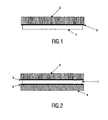
- FIG. 1 In the schematic representation after FIG. 1 is a substantially disc-shaped workpiece 1, in particular a thin semiconductor wafer, flat along its first major surface, which forms the top in the illustrated position of the workpiece 1, fixed by means of a first bond 3 on a first, at least substantially rigidly designed workpiece carrier 2.
- the first adhesion 3 is preferably made with a first adhesive layer formed as the first double-sided adhesive film 3.
- This first double-sided adhesive film 3 consists in a conventional manner of a film-shaped plastic body whose two surfaces are covered with adhesive layers. In this case, a first of these surfaces with a first adhesive layer faces the first workpiece carrier 2 and a second of these surfaces with a second adhesive layer faces the workpiece 1.
- a representation of this assignment can be found in FIG. 4 ,
- the presentation of the Fig. 2 schematically shows the next process step.
- the workpiece 1 and the first workpiece carrier 2 are at least largely adhesive on a second major surface of the workpiece 1, which is opposite to the first main surface and in the illustrated position of the workpiece 1 forms its underside, with the aid of a second bond 5 on a second, at least attached largely rigid trained workpiece carrier 4.
- the adhesive force of the second bond 5 is significantly greater than the adhesive force of the first bond 3.
- the second bond 5 is preferably made with an adhesive layer formed as a double-sided adhesive film; this adhesive layer, referred to below as the second adhesive layer, is formed by a second double-sided adhesive film.
- the second double-sided adhesive film 5 is also in a conventional manner of a film-shaped plastic body, the two surfaces are covered with adhesive layers. In this case, a first of these surfaces with a third adhesive layer facing the second workpiece carrier 4 and a second of these surfaces with a fourth adhesive layer facing the workpiece 1.
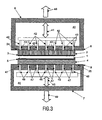
- Fig. 3 shows in a first embodiment, as in Fig. 2 shown schematically Arrangement of workpiece 1, workpiece carriers 2, 4 and connecting them bonds 3, 5 is arranged between two holding devices. Therein, the first workpiece carrier 2 is fastened to a first of these holding devices with the reference numeral 6, and the second workpiece carrier 4 is fastened to the second of these holding devices by the reference numeral 7.
- the attachment of the first workpiece carrier 2 to the first holding device 6 takes place in this first embodiment by means of a third bond 8, and the attachment of the second workpiece carrier 4 to the second holding device 7 by means of a fourth bond 9.
- the adhesive forces of the third bond 8 between The first workpiece carrier 2 and the first holding device 6 and the fourth bond 9 between the second workpiece carrier 4 and the second holding device 7 are significantly greater than the adhesive force of the first bond 3 and also greater than the adhesive force of the second bond 5. This ensures that during the separation process, the first bond 3 is first separated.
- the third and the fourth bond 8, 9 can again preferably be made with double-sided adhesive films-a third and a fourth double-sided adhesive film.
- Each of these double-sided adhesive films 8 and 9 again consists of a film-shaped plastic body whose two surfaces are covered with adhesive layers.
- a first of these surfaces of the fourth double-sided adhesive film 9 with a seventh adhesive layer facing the second workpiece carrier 4 and a second of these surfaces of the fourth double-sided adhesive film 9 with an eighth adhesive layer of the second holding device 7 FIG. 4
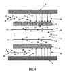
- Fig. 4 are in a schematic representation of the aforementioned surfaces and adhesive layers designated in more detail in their assignment to each other.
- the reference signs of which have been kept unchanged the following further elements are outlined with the following reference signs: the first main surface 10 and the second one Main surface 11 of the workpiece 1; the plastic body 12, the first surface 13 with the first adhesive layer 15, and the second surface 14 with the second adhesive layer 16 of the first double-sided adhesive film 3; the plastic body 17, the first surface 18 with the third adhesive layer 20 and the second surface 19 with the fourth adhesive layer 21 of the second double-sided adhesive film 5; the plastic body 22, the first surface 23 with the fifth adhesive layer 25 and the second surface 24 with the sixth adhesive layer 26 of the third double-sided adhesive film 8; the plastic body 27, the first surface 28 with the seventh adhesive layer 30, and the second surface 29 with the eighth adhesive layer 31 of the fourth double-sided adhesive film 9.
- the weakest adhesive force In a formation of the first bond as the first double-sided adhesive film 3, preferably the second adhesive layer 16 with respect to the workpiece 1, the weakest adhesive force, whereby when separating the workpiece 1 from the first workpiece carrier 2, this first double-sided adhesive film 3 remains on the first workpiece carrier 2 and thus releasing the workpiece 1.
- a magnetic field 32 between the first holding device 6 and the first workpiece carrier 2 and in place of the fourth bond 9 a magnetic field 33 between the second holding device 7 and the second workpiece carrier 4 drawn.
- the workpiece carriers 2,4 are formed with ferromagnetic material.
- the holding devices 6, 7 have an optionally effective or ineffective adjustable first or second magnetic device for attaching the associated workpiece carriers 2 and 4 to the holding devices by means of magnetic attraction.
- the occurring magnetic forces between the holding device 6 and 7 and the associated workpiece carrier 2 and 4 are chosen to be significantly larger than the adhesive force of the first bond 3.
- FIG. 4 For orientation, the following elements are also designated: A surface 34 of the first holding device 6, along which the first holding device 6 with the first Workpiece carrier 2 is connected at least largely flat; a surface 35 of the second holding device 7, along which the second holding device 7 is connected to the second workpiece carrier 4 at least substantially flat; a surface 36 of the first workpiece carrier 2, along which the first workpiece carrier 2 is connected to the surface 34 of the first holding device 6 at least substantially flat; a surface 37 of the first workpiece carrier 2, along which the first workpiece carrier 2 is connected to the first main surface 10 of the workpiece 1 at least substantially flat; a surface 38 of the second workpiece carrier 4, along which the second workpiece carrier 4 is connected to the second main surface 11 of the workpiece 1 at least extensively flat; and a surface 39 of the second workpiece carrier 4, along which the second workpiece carrier 4 is connected to the surface 35 of the second holding device 7 at least substantially flat.
- the first holding device 6 comprises a first ejecting device 40.
- This is provided with a plunger 41 and ejector pins 42 are formed.
- the ejector pins 42 are guided through recesses (for example bores) 43 in the surface 34 facing the first workpiece carrier 2, so that they can enter into frictional connection with the first workpiece carrier 2.
- the second holding device 7 a second ejection device 44.
- This is formed with a plunger 45 and ejector 46.
- the ejector pins 46 are guided through recesses (for example bores) 47 in the surface 35 facing the second workpiece carrier 4, so that they can enter into frictional connection with the second workpiece carrier 4.
- recesses for example bores
- Fig. 3 shows the first embodiment of the device according to the invention after completion of the process step in which the holding devices 6, 7 with the workpiece carriers 2.4 get connected.
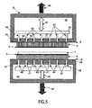
- Fig. 5 shows the arrangement after Fig. 3 Following the next process step, wherein the elements already described are again provided with identical packszieichen
- the first adhesive bond 3 and from it in training with a double-sided adhesive film, in particular the second adhesive layer 16 dissolves as the weakest connection between said elements of the arrangement.
- the state of the arrangement is shown after this separation process.
- Fig. 6 schematically shows the implementation of the next method steps in the embodiment of the arrangement according to Fig. 3 and 5 following separation of the workpiece carrier 2, 4 of the holding devices 6, 7.
- the elements already described are again provided with the same reference numerals.
- the first workpiece carrier 2 is separated from the first holding device 6 by operating the plunger 41 of the first ejection device 40 according to this embodiment. This is indicated by the dark hatching of the arrow 41.
- the pressure punch 41 moves the ejector pins 42 through the recesses 43 against the first workpiece carrier 2 and thereby solves the third bond 8. If this is formed in the manner described as a double-sided adhesive film which adheres to the surface 34, in this separation process in particular the fifth Adhesive layer 25 dissolved on the first surface 23 of this film.
- the film remains on the first holding device 6 and can for the next connection of the first holding device 6 with a (further) first workpiece carrier 2 (for another workpiece 1) are used.
- the third double-sided adhesive film 8 is perforated in the region of the recesses 43 corresponding to their cross section or the cross section of the ejector pins 42.
- FIG Fig. 10 A thus formed surface 34 of the first holding device 6 with the third double-sided adhesive film 8 is shown schematically in FIG Fig. 10 will be discussed in the following.
- the arrangement after Fig. 6 further comprises a receiver 50 for receiving the first workpiece carrier 2 after its detachment from the first holding device 6. On this receiver 50, the first workpiece carrier 2 is stored for further use.
- Holding device 7 separate second workpiece carrier 4 are used with the workpiece 1.
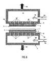
- Fig. 7 shows a modification of the above arrangement and the method performed therewith a second embodiment of the invention.
- This includes the ejectors of the holding devices 6, 7 instead of the plunger 41, 45 and ejector pins 42, 46 depending on a compressed gas device 51 and 52, by means of which the workpiece carrier 2 or 4 by Pressure on the surface 34 and 35 of the respective holding device 6 and 7 facing surface 36 and 39 of the first and second workpiece carrier 2 and 4 are separated from said, respective holding device 6 and 7 respectively.
- a compressed gas device 51 and 52 by means of which the workpiece carrier 2 or 4 by Pressure on the surface 34 and 35 of the respective holding device 6 and 7 facing surface 36 and 39 of the first and second workpiece carrier 2 and 4 are separated from said, respective holding device 6 and 7 respectively.
- the first of the two compressed gas devices with the reference numeral 51 in the first holding device 6 comprises a first compressed gas port 53, through which a compressed gas, which in the simplest case consists of compressed air, but may also have a different composition, if this is desirable for the handling of the workpieces (Protective gas), is passed into a cavity referred to as a pressure chamber, which is formed in the first holding device 6.
- This pressure chamber connects the first compressed gas connection 53 with the recesses 43 in the surface 34 of the first holding device 6, which now serve as gas outlet openings.
- an arrow 55 the introduction of compressed gas and thus the force on the first workpiece carrier 2 is indicated.
- the second of the two compressed gas devices with the reference numeral 52 in the second holding device 7 comprises a second compressed gas port 54, through which the compressed gas is passed into a further pressure chamber, which is formed in accordance with the second holding device 7.
- This further pressure chamber connects the second compressed gas connection 54 with the now serving as gas outlet openings 47 in the surface 35 of the second holding device 7.
- Fig. 8 shows the arrangement after Fig. 7 following the next method step, wherein the elements already described are again provided with identical reference numerals. Due to the effect of the applied to the holding devices 6 and 7 tensile forces, their effectiveness as in the first embodiment according to Fig. 3 is indicated by dark hatching of the arrows 48 and 49, the configuration of the holding devices 6, 7, the workpiece carriers 2, 4 and the workpiece 1 is pulled apart. In this case, the first bond 3 dissolves again and, when it is formed with a double-sided adhesive film, in particular the second adhesive layer 16 as the weakest connection between the elements of the arrangement mentioned. In Fig. 8 is the state of the arrangement after shown this separation process.
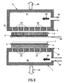
- Fig. 9 schematically shows the implementation of the next method steps in the embodiment of the arrangement according to Fig. 7 and 8th following separation of the workpiece carrier 2, 4 of the holding devices 6, 7.
- the elements already described are again provided with the same reference numerals.
- the first workpiece carrier 2 is separated from the first holding device 6 by operating the first compressed gas device 51 according to this embodiment. This is indicated by the dark hatching of the arrow 55.
- the pressure of the compressed gas acts through the recesses 43 on the first workpiece carrier 2 and thereby solves the third bond 8. Is this again in the manner already described as a double-sided adhesive film adhering to the surface 34, in this separation process in particular the fifth Adhesive layer 25 dissolved on the first surface 23 of this film.
- the film remains on the first holding device 6 and can be used for the next connection of the first holding device 6 with a (further) first workpiece carrier 2 (for another workpiece 1).
- the third double-sided adhesive film 8 is perforated in the region of the recesses 43 corresponding to the cross section thereof.
- a thus formed surface 34 of the first holding device 6 with the third double-sided adhesive film 8 corresponds in its design schematically the Fig. 10 , which will be discussed below.
- the arrangement after Fig. 9 comprises a pickup 50 for receiving the first workpiece carrier 2 after its detachment from the first holding device 6. On this pickup 50, the first workpiece carrier 2 is stored for further use.
- the second workpiece carrier 4 is separated from the second holding device 7 also in this second embodiment.
- the second compressed gas device 52 is used for this purpose; the operation is indicated by the dark hatching of the arrow 56.
- the fourth bond 9 is released; at training the fourth bond 9 as double-sided adhesive film is again preferably its seventh adhesive layer 30, which is located on the first surface 28 of the fourth double-sided adhesive film 9, separated, so that here the double-sided adhesive film 9 on the surface 35 of the second holding device 7 remains , A trained according to the transducer 50, not shown pickup can be used to take over the second holding device 7 separate second workpiece carrier 4 with the workpiece 1.
- Fig. 10 shows an embodiment of the surface 34 of the first holding device 6 with the attached thereon third double-sided adhesive film 8 and the recesses 43 for the Auswerferite 42.
- the third double-sided adhesive film 8 has recesses whose position coincides with that of the recesses 43.
- the ejector pins 42 can exert pressure on the first workpiece carrier 2 without detaching the third double-sided adhesive film 8 from the surface 34.
- Fig. 10 is also the second holder 7 designed with the surface 35, wherein in place of the third double-sided adhesive film 8, the fourth double-sided adhesive film 9, in place of the recesses 43, the recesses 47 and the ejector pins 42, the ejector 46 occur.
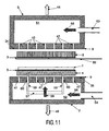
- Fig. 11 shows a modification of the in the FIGS. 7 . 8th and 9
- a second Ejector 57 in a modification of the second ejector 44, as shown in the Figures 3 . 5 and 6 of the first embodiment, comprises a number of ejector pins 57, which may preferably be smaller than that of the ejector pins 46.
- the ejector pins 59 are guided by recesses 60.
- Fig. 11 shows this third embodiment in a state comparable to that Fig. 9 .
- the ejector pins 59 of the second ejector 57 are extended, which is shown in FIG Fig. 11 is indicated by the dark hatched arrow 58.
- the already dissolved second workpiece carrier 4 is repealed by the Auswerferiten 59, wherein in particular the spatial distance between the surface 35 and the second workpiece carrier 4 can be increased in a simple and defined manner, and the second workpiece carrier 4 can, for. B. in the manner already mentioned on a second pickup, are removed from the second holder 7.
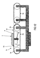
- Fig. 12 shows a schematic representation of a modification for an embodiment of a holding device on the example of the holding device for the second workpiece carrier 4 in training with a magnetic device and flat band-shaped, rollable support elements according to a fourth embodiment.
- This modification of the holding device is designated by the reference numeral 71.
- the holding device 71 comprises an electromagnet 72, on the outer, at least substantially flat surface 73, a first treadmill 76 - preferably formed as a continuous running belt and steel - rests, which is placed around two rollers 74, 75 and can be rolled through them.
- On this first treadmill 76 which further preferably on its side facing away from the electromagnet 72 with an adhesive layer 77 - formed, for example, as a double-sided adhesive film - is covered, is the second workpiece carrier 4 with the workpiece 1.
- the second workpiece carrier 4 is formed with a ferromagnetic material so that it can be attracted by the electromagnet 72.
- the holding device 71 can also be used as the first holding device for the first workpiece carrier 2.
- the solenoid 72 is turned on.
- the magnetic attraction is indicated by a dark hatched arrow 79.
- the adhesive layer 77 creates a fixation on the first treadmill.
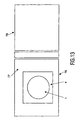
- Fig. 13 shows the arrangement with the holding device 71, the first conveyor belt 76, the second workpiece carrier 4 and the workpiece 1 in the schematic plan view.
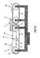
- the electromagnet 72 After the separation of the first bond 3, the electromagnet 72 according to Fig. 14 switched off and thus the second workpiece carrier 4 released from the holding device 71.
- the switching off of the electromagnet 72 is by omitting the hatching of the arrow 79 in FIG Fig. 14 indicated.
- the first conveyor belt 76 is unrolled and thus the second workpiece carrier 4 is removed from the area of action of the electromagnet 72.
- the second workpiece carrier 4 is moved down by the unrolling of the first treadmill 76 and onto a second treadmill 78, wherein at the same time the adhesive layer 77 is automatically separated.
- the second treadmill is preferably permeable to air and formed without adhesive layer and serves for the further transport of the second workpiece carrier 4.
- the arrows 80 denote the Direction of movement of the treadmills 76 and 78 when unrolling.
- the described methods and apparatus for securing the workpiece carriers to the fixtures and for separating the workpiece carriers from the fixtures may also be combined such that different arrangements and methods are used for the first and second fixtures.
- a second holding device according to the fourth embodiment according to Fig. 12 to 14 with a first holding device according to the second embodiment according to Fig. 7 to 9 be combined.
Landscapes
- Container, Conveyance, Adherence, Positioning, Of Wafer (AREA)
- Specific Conveyance Elements (AREA)
- Packaging For Recording Disks (AREA)
- Grinding Of Cylindrical And Plane Surfaces (AREA)
- Constituent Portions Of Griding Lathes, Driving, Sensing And Control (AREA)
- Manufacturing Of Magnetic Record Carriers (AREA)
Claims (25)
- Procédé de transfert d'une pièce (1) en forme essentiellement de disque d'un premier porte-pièce (4), sur lequel la pièce est reliée en adhérant au moins en grande partie à plat le long d'une première de ses surfaces principales au moyen d'un premier collage (3), à un second porte-pièce (4), comprenant les étapes de procédé suivantes consistant à :- fixer le second porte-pièce (4) en adhérant au moins en grande partie à plat sur une deuxième de ses surfaces principales opposée à la première surface principale de la pièce (1) au moyen d'un deuxième collage (5), dont la force adhésive est nettement plus grande que la force adhésive du premier collage,- fixer le premier porte-pièce (2) sur un premier dispositif de retenue (6),caractérisé en outre par les étapes de procédé suivantes consistant à :- fixer le second porte-pièce (2) sur un second dispositif de retenue (6),- séparer la pièce (1) reliée de manière adhésive au premier porte-pièce (7) au moyen du premier collage (3) du premier porte-pièce (2) le long du premier collage (3) par application d'une force de traction (48, 49) au moins partiellement verticale par rapport aux surfaces principales de la pièce (1) entre le premier et le second dispositifs de retenue (6, 7), le premier collage (3) étant séparé lors de l'application de la force de traction (48, 49) entre les dispositifs de retenue (6, 7), alors que le deuxième collage (5) retient la pièce (1) sur le second porte-pièce (4),- séparer le premier porte-pièce (2) du premier dispositif de retenue (6),- séparer le second porte-pièce (4) avec la pièce (1) reliée à celui-ci du second dispositif de retenue (7).
- Procédé selon la revendication 1,
caractérisé en ce
que des portes-pièces réalisés au moins en grande partie de manière rigide sont utilisés comme portes-pièces (6, 7). - Procédé selon la revendication 1 ou 2,
caractérisé en ce
que la fixation du premier porte-pièce (2) sur le premier dispositif de retenue (6) est entreprise par un troisième collage (8), la force adhésive du troisième collage (8) entre le premier porte-pièce (2) et le premier dispositif de retenue (6) étant nettement plus grande que la force adhésive du premier collage (3). - Procédé selon la revendication 1 ou 2,
caractérisé en ce
que la fixation du second porte-pièce (4) sur le second dispositif de retenue (7) est entreprise par un quatrième collage (9), la force adhésive du quatrième collage (9) entre le second porte-pièce (4) et le second dispositif de retenue (7) étant nettement plus grande que la force adhésive du premier collage (3). - Procédé selon la revendication 1 ou 2,
caractérisé en ce
que le premier porte-pièce (2) est réalisé avec du matériau ferromagnétique et la fixation du premier porte-pièce (2) sur le premier dispositif de retenue (6) est entreprise par un premier dispositif magnétique réglable au choix efficacement ou inefficacement qui génère une attraction magnétique entre le premier porte-pièce (2) et le premier dispositif de retenue (6) avec une première force magnétique qui est nettement plus grande que la force adhésive du premier collage (3). - Procédé selon la revendication 1 ou 2,
caractérisé en ce
que le second porte-pièce (4) est réalisé avec du matériau ferromagnétique et la fixation du second porte-pièce (4) sur le second dispositif de retenue (7) est entreprise par un second dispositif magnétique réglable au choix efficacement ou inefficacement qui génère une attraction magnétique entre le second porte-pièce (4) et le second dispositif de retenue (7) avec une seconde force magnétique qui est nettement plus grande que la force adhésive du premier collage (3). - Procédé selon la revendication 3 ou 4,
caractérisé en ce
que pour la séparation d'au moins l'un des dispositifs de retenue (6, 7) du porte-pièce (2, 4) fixé sur lui, un dispositif d'éjection (44) compris par au moins l'un de ces dispositifs de retenue (6, 7) est utilisé. - Procédé selon la revendication 7,
caractérisé en ce
que pour la séparation du dispositif de retenue (6, 7) du porte-pièce (2, 4) fixé sur lui, un dispositif d'éjection comportant au moins une tige d'éjection (42 (46), 59) est utilisé, dans lequel au moyen de la tige d'éjection (46), le porte-pièce (2, 4) fixé sur ce dispositif de retenue (6, 7) est détaché du dispositif de retenue (6, 7) par une pression sur le coté du porte-pièce (2, 4) qui est tourné vers le dispositif de retenue (6, 7) pour la fixation du porte-pièce (2, 4) sur ce dispositif de retenue (6, 7). - Procédé selon la revendication 7,
caractérisé en ce
que pour la séparation du dispositif de retenue (6, 7) du porte-pièce (2, 4) fixé sur lui, un dispositif d'éjection comportant au moins un dispositif à gaz comprimé est utilisé, dans lequel au moyen du dispositif à gaz comprimé, le porte-pièce fixé sur ce dispositif de retenue est détaché du dispositif de retenue par une pression sur le coté du porte-pièce qui est tourné vers le dispositif de retenue pour la fixation du porte-pièce sur ce dispositif de retenue. - Procédé selon la revendication 5 ou 6,
caractérisé en ce
que pour au moins l'un des dispositifs de retenue (6, 7), sur lequel la fixation du porte-pièce (2, 4) est entreprise avec un dispositif aimanté (72), le porte-pièce (2, 4) est disposé sur un élément d'appui (76, 78) configuré essentiellement plan, mobile par rapport au dispositif aimanté, lequel élément d'appui est déplacé pour la séparation du porte-pièce (2, 4) du dispositif de retenue (6, 9) conjointement avec le porte-pièce (2, 4) hors de la zone d'action du dispositif aimanté (72). - Procédé selon la revendication 10,
caractérisé en ce
qu'au moins l'un des portes-pièces (6, 7) est disposé sur un premier élément d'appui (76) déroulable, en forme de bande plate, formé de préférence en acier et le porte-pièce (2, 4) est transféré pour la séparation du dispositif de retenue (6, 7) par déroulement du premier élément d'appui (76) en forme de bande plate à un second élément d'appui (78) en forme de bande plate. - Procédé selon la revendication 1, 4 ou 5,
caractérisé en ce
qu'au moins l'un des collages (3, 5) est réalisé avec un film collant des deux côtés. - Dispositif pour effectuer un procédé selon l'une quelconque des revendications précédentes de transfert d'une pièce (1) en forme essentiellement de disque d'un premier porte-pièce (2), sur lequel la pièce (1) est reliée en adhérant au moins en grande partie à plat le long d'une première de ses surfaces principales au moyen d'un premier collage (3), à un second porte-pièce (4), sur lequel la pièce (1) doit être appliquée et fixée en adhérant au moins en grande partie à plat sur une deuxième de ses surfaces principales opposée à la première surface principale de la pièce (1) au moyen d'un deuxième collage (5), dont la force adhésive est nettement plus grande que la force adhésive du premier collage (3), un premier dispositif de retenue (6) pour la fixation du premier porte-pièce (2) sur ce premier dispositif de retenue (6), et
caractérisé par un second dispositif de retenue (7) pour la fixation du second porte-pièce (4) sur ce second dispositif de retenue (7) et un dispositif de traction pour l'application d'une force de traction (48, 49) au moins partiellement verticale par rapport aux surfaces principales de la pièce entre le premier et le second dispositifs de retenue (6, 7). - Dispositif selon la revendication 13,
caractérisé en ce
que la pièce (1) est un produit de la technique des semi-conducteurs, de préférence un disque semi-conducteur qui est conçu le long d'au moins sa seconde surface principale pour la réalisation d'un nombre de corps de circuits électroniques, à séparer mécaniquement essentiellement verticalement par rapport à la seconde surface principale. - Dispositif selon la revendication 13 ou 14,
caractérisé en ce
que les portes-pièces (2, 4) sont réalisés au moins essentiellement de manière rigide. - Dispositif selon la revendication 13, 14 ou 15,
caractérisé en ce
que la fixation du premier porte-pièce (2) sur le premier dispositif de retenue (6) est réalisée comme un troisième collage (8), la force adhésive du troisième collage (8) entre le premier porte-pièce (2) et le premier dispositif de retenue (6) étant nettement plus grande que la force adhésive du premier collage (3). - Dispositif selon la revendication 13, 14 ou 15,
caractérisé en ce
que la fixation du second porte-pièce (4) sur le second dispositif de retenue (7) est réalisée comme un quatrième collage (9), la force adhésive du quatrième collage (9) entre le second porte-pièce (4) et le second dispositif de retenue (7) étant nettement plus grande que la force adhésive du premier collage (3). - Dispositif selon la revendication 13, 14 ou 15,
caractérisé par
une réalisation du premier porte-pièce (2) avec du matériau ferromagnétique ainsi que par un premier dispositif aimanté réglable au choix efficacement ou inefficacement pour la fixation du premier porte-pièce (2) sur le premier dispositif de retenue (6) à l'aide d'une attraction magnétique entre le premier porte-pièce (2) et le premier dispositif de retenue (6) avec une première force magnétique qui est nettement plus grande que la force adhésive du premier collage (3). - Dispositif selon la revendication 13, 14 ou 15,
caractérisé par
une réalisation du second porte-pièce (4) avec du matériau ferromagnétique ainsi que par un second dispositif aimanté réglable au choix efficacement ou inefficacement pour la fixation du second porte-pièce (4) sur le second dispositif de retenue (7) à l'aide d'une attraction magnétique entre le second porte-pièce (4) et le second dispositif de retenue (7) avec une seconde force magnétique qui est nettement plus grande que la force adhésive du premier collage (3). - Dispositif selon la revendication 16 ou 17,
caractérisé par
un dispositif d'éjection compris par au moins l'un des dispositifs de retenue (6, 7) pour la séparation d'au moins l'un de ces dispositifs de retenue (6, 7) du porte-pièce (2, 4) fixé sur lui. - Dispositif selon la revendication 20,
caractérisé en ce
que le dispositif d'éjection (44) pour la séparation du dispositif de retenue (6, 7) du porte-pièce fixé sur lui comporte au moins une tige d'éjection (42, 46, 59), au moyen de laquelle le porte-pièce (2, 4) peut être détaché de ce dispositif de retenue (6, 7) par une pression sur le côté tourné vers le dispositif de retenue (6, 7) du porte-pièce (2, 4). - Dispositif selon la revendication 20,
caractérisé en ce
que le dispositif d'éjection pour la séparation du dispositif de retenue du porte-pièce fixé sur lui comporte au moins un dispositif à gaz comprimé, au moyen duquel le porte-pièce peut être détaché de ce dispositif de retenue par une pression sur le côté tourné vers le dispositif de retenue du porte-pièce. - Dispositif selon la revendication 18 ou 19,
caractérisé en ce
qu'au moins l'un des dispositifs de retenue (6, 7) réalisé avec un dispositif aimanté est configuré avec un premier élément d'appui mobile par rapport au dispositif aimanté (72), configuré essentiellement plan, pouvant être déplacé pour la séparation du porte-pièce (2, 4) du dispositif de retenue (6, 7) conjointement avec le porte-pièce (2, 4) hors de la zone d'action du dispositif aimanté (72) pour la réception du porte-pièce. - Dispositif selon la revendication 23,
caractérisé en ce
que le premier élément d'appui (76) ou les premiers éléments d'appui est ou sont réalisés en forme de bande plate et déroulables pour la séparation des portes-pièces du dispositif de retenue (6, 7) ou des dispositifs de retenue, de préférence en acier et en ce que le dispositif de retenue (6, 7) concerné est configuré avec un second élément d'appui (78) en forme de bande plate ou les dispositifs de retenue concernés sont configurés avec des seconds éléments d'appui en forme de bande plate, auquel ou auxquels le porte-pièce peut être transféré du premier élément d'appui en forme de bande plate par déroulement de celui-ci. - Dispositif selon la revendication 24,
caractérisé en ce
qu'au moins l'un des premiers éléments d'appui (76, 78) en forme de bande plate présente pour la réception du porte-outil sur sa surface en outre au moins partiellement une couche de colle ou un film collant des deux côtés.
Applications Claiming Priority (2)
| Application Number | Priority Date | Filing Date | Title |
|---|---|---|---|
| DE10128924A DE10128924A1 (de) | 2001-06-15 | 2001-06-15 | Verfahren zum Umsetzen eines im wesentlichen scheibenförmigen Werkstücks sowie Vorrichtung zum Durchführen dieses Verfahrens |
| DE10128924 | 2001-06-15 |
Publications (3)
| Publication Number | Publication Date |
|---|---|
| EP1267390A2 EP1267390A2 (fr) | 2002-12-18 |
| EP1267390A3 EP1267390A3 (fr) | 2004-08-25 |
| EP1267390B1 true EP1267390B1 (fr) | 2010-04-07 |
Family
ID=7688306
Family Applications (1)
| Application Number | Title | Priority Date | Filing Date |
|---|---|---|---|
| EP02100696A Expired - Lifetime EP1267390B1 (fr) | 2001-06-15 | 2002-06-12 | Procédé de transfert d'une pièce en forme essentiellement de disque et dispositif pour effectuer d'un tel transfert |
Country Status (5)
| Country | Link |
|---|---|
| US (1) | US6827809B2 (fr) |
| EP (1) | EP1267390B1 (fr) |
| JP (1) | JP4209141B2 (fr) |
| AT (1) | ATE463836T1 (fr) |
| DE (2) | DE10128924A1 (fr) |
Families Citing this family (13)
| Publication number | Priority date | Publication date | Assignee | Title |
|---|---|---|---|---|
| TW484184B (en) * | 1998-11-06 | 2002-04-21 | Canon Kk | Sample separating apparatus and method, and substrate manufacturing method |
| JP3772954B2 (ja) * | 1999-10-15 | 2006-05-10 | 株式会社村田製作所 | チップ状部品の取扱方法 |
| DE10260233B4 (de) * | 2002-12-20 | 2016-05-19 | Infineon Technologies Ag | Verfahren zum Befestigen eines Werkstücks mit einem Feststoff an einem Werkstückträger und Werkstückträger |
| US20050150597A1 (en) * | 2004-01-09 | 2005-07-14 | Silicon Genesis Corporation | Apparatus and method for controlled cleaving |
| JP4570084B2 (ja) * | 2005-02-10 | 2010-10-27 | 日東電工株式会社 | 基板貼合せ方法 |
| DE102005021048A1 (de) * | 2005-05-06 | 2006-12-28 | Infineon Technologies Ag | Vorrichtung zum Stabilisieren eines Werkstücks bei einer Bearbeitung |
| DE102008055155B4 (de) * | 2008-12-23 | 2026-07-30 | Nissan Chemical Industries, Ltd. | Trennverfahren für ein Schichtsystem umfassend einen Wafer, Verwendung einer Polymethacrylatscheibe bei dem Verfahren und Vorrichtung zum Durchführen des Verfahrens |
| US8950459B2 (en) | 2009-04-16 | 2015-02-10 | Suss Microtec Lithography Gmbh | Debonding temporarily bonded semiconductor wafers |
| US8366873B2 (en) * | 2010-04-15 | 2013-02-05 | Suss Microtec Lithography, Gmbh | Debonding equipment and methods for debonding temporary bonded wafers |
| JP5773372B2 (ja) * | 2013-05-13 | 2015-09-02 | リンテック株式会社 | ワーク受渡し機構を有する装置 |
| CN206067049U (zh) | 2016-07-29 | 2017-04-05 | 合肥鑫晟光电科技有限公司 | 膜材以及撕膜装置 |
| CN106965501B (zh) * | 2017-03-27 | 2019-07-05 | 合肥鑫晟光电科技有限公司 | 一种膜状结构、撕膜设备及撕膜方法 |
| KR20250081568A (ko) * | 2023-11-29 | 2025-06-05 | 삼성전자주식회사 | 칩 이젝터 장치 |
Family Cites Families (10)
| Publication number | Priority date | Publication date | Assignee | Title |
|---|---|---|---|---|
| US4462873A (en) * | 1982-07-16 | 1984-07-31 | Eiji Watanabe | Method of fixedly arranging an array of electroformed letters or the like on an article |
| JPS60169148A (ja) * | 1984-02-13 | 1985-09-02 | Dainippon Screen Mfg Co Ltd | 基板の搬送方法及びその装置 |
| US5224581A (en) * | 1989-12-14 | 1993-07-06 | Applied Materials, Inc. | Magnetic semiconductor wafers with handling apparatus and method |
| US5476566A (en) * | 1992-09-02 | 1995-12-19 | Motorola, Inc. | Method for thinning a semiconductor wafer |
| US5324687A (en) * | 1992-10-16 | 1994-06-28 | General Electric Company | Method for thinning of integrated circuit chips for lightweight packaged electronic systems |
| JPH06268051A (ja) * | 1993-03-10 | 1994-09-22 | Mitsubishi Electric Corp | ウエハ剥し装置 |
| US5958794A (en) * | 1995-09-22 | 1999-09-28 | Minnesota Mining And Manufacturing Company | Method of modifying an exposed surface of a semiconductor wafer |
| US6173750B1 (en) * | 1998-02-18 | 2001-01-16 | Hover-Davis, Inc. | Method and apparatus for removing die from a wafer and conveying die to a pickup location |
| DE19850873A1 (de) * | 1998-11-05 | 2000-05-11 | Philips Corp Intellectual Pty | Verfahren zum Bearbeiten eines Erzeugnisses der Halbleitertechnik |
| EP1041624A1 (fr) * | 1999-04-02 | 2000-10-04 | Interuniversitair Microelektronica Centrum Vzw | Methode de transfert de substrates ultra-minces et mis en oeuvre de sa methode dans la fabrication de dispositifs de type couches minces |
-
2001
- 2001-06-15 DE DE10128924A patent/DE10128924A1/de not_active Withdrawn
-
2002
- 2002-06-12 US US10/170,030 patent/US6827809B2/en not_active Expired - Fee Related
- 2002-06-12 AT AT02100696T patent/ATE463836T1/de not_active IP Right Cessation
- 2002-06-12 DE DE50214330T patent/DE50214330D1/de not_active Expired - Lifetime
- 2002-06-12 EP EP02100696A patent/EP1267390B1/fr not_active Expired - Lifetime
- 2002-06-17 JP JP2002176306A patent/JP4209141B2/ja not_active Expired - Fee Related
Also Published As
| Publication number | Publication date |
|---|---|
| DE50214330D1 (de) | 2010-05-20 |
| US6827809B2 (en) | 2004-12-07 |
| JP4209141B2 (ja) | 2009-01-14 |
| DE10128924A1 (de) | 2003-01-23 |
| EP1267390A3 (fr) | 2004-08-25 |
| JP2003086662A (ja) | 2003-03-20 |
| EP1267390A2 (fr) | 2002-12-18 |
| US20030000635A1 (en) | 2003-01-02 |
| ATE463836T1 (de) | 2010-04-15 |
Similar Documents
| Publication | Publication Date | Title |
|---|---|---|
| DE69908395T2 (de) | Chirurgischer wundverband mit abgabesystem und verfahren zu seiner herstellung | |
| EP0529438B1 (fr) | Dispositif pour séparer et enlever une feuille d'un matériau support laminé | |
| EP1267390A2 (fr) | Procédé de transfert d'une pièce en forme essentiellement de disque et dispositif pour effectuer d'un tel transfert | |
| WO2018078132A1 (fr) | Dispositif et procédé de liaison de pièces de tôle pour obtenir un noyau feuilleté | |
| EP2295355B1 (fr) | Procédé, dispositif et bande adhésive pour l'épissage de bandes d'étiquettes et bande d'étiquettes pouvant être épissées | |
| DE69827534T2 (de) | Verfahren zur Laminierung von Plattensubstraten | |
| DE60214182T2 (de) | Methode und vorrichtung zur überführung eines scheibenförmigen werkstücks | |
| EP0479715B1 (fr) | Fermeture pour bande | |
| DE19521022C2 (de) | Verfahren zur Herstellung eines Schichtverbundes | |
| EP1216034B1 (fr) | Procede et dispositif de distribution de portions de stratifie a adhesion de contact a partir d'une feuille support primaire mobile sur une feuille support secondaire mobile | |
| WO2001032044A1 (fr) | Procede de production d'une partie de fermeture adhesive | |
| EP0525692B1 (fr) | Dispositif pour séparer et enlever une feuille d'un matériau support laminé | |
| DE19744991C2 (de) | Verfahren zur Messung der Anfangshaftung einer Haftkleberschicht und Vorrichtung zur Durchführung eines solchen Verfahrens | |
| DE102010004092A1 (de) | Vorrichtung und Verfahren zur Bekantung von Werkstücken | |
| DE60133528T2 (de) | Automatische Trennvorrichtung und Verfahren zur Erzeugung von Schaltungen für die Mikroelektronik | |
| DE69112646T2 (de) | Verfahren und vorrichtung zur herstellung von etiketten. | |
| DE4033834A1 (de) | Verfahren zum herstellen eines ununterbrochenen aufkleberblattes | |
| EP0790205A2 (fr) | Rouleau d'étiquettes avec élément de raccordement | |
| WO2025082707A1 (fr) | Procédé et dispositif de fabrication pour création de languettes de fermeture de couche, et couche avec languettes de fermeture | |
| DE102005006978B3 (de) | Verfahren und Vorrichtung zum Verbinden von Halbleiterelementen oder Interposern mit einem Trägerband und Verwendung einer derartigen Vorrichtung | |
| EP1097083A1 (fr) | Procede et dispositif pour la fabrication de produits adhesifs en surface, a partir d'un stratifie, leur transfert sur une feuille de recouvrement et leur presentation finale | |
| DE102006018499A1 (de) | Verfahren zur Herstellung eines Klebebands | |
| EP0186080B1 (fr) | Procédé de fabrication d'un élément adhésif à propriétés thermoplastiques et son procédé d'utilisation | |
| EP4124449A1 (fr) | Étiquette, bande d'étiquettes et procédé de fabrication d'étiquettes | |
| EP0514952A2 (fr) | Support d'impression |
Legal Events
| Date | Code | Title | Description |
|---|---|---|---|
| PUAI | Public reference made under article 153(3) epc to a published international application that has entered the european phase |
Free format text: ORIGINAL CODE: 0009012 |
|
| AK | Designated contracting states |
Kind code of ref document: A2 Designated state(s): AT BE CH CY DE DK ES FI FR GB GR IE IT LI LU MC NL PT SE TR |
|
| AX | Request for extension of the european patent |
Free format text: AL;LT;LV;MK;RO;SI |
|
| RAP1 | Party data changed (applicant data changed or rights of an application transferred) |
Owner name: KONINKLIJKE PHILIPS ELECTRONICS N.V. Owner name: PHILIPS INTELLECTUAL PROPERTY & STANDARDS GMBH |
|
| PUAL | Search report despatched |
Free format text: ORIGINAL CODE: 0009013 |
|
| AK | Designated contracting states |
Kind code of ref document: A3 Designated state(s): AT BE CH CY DE DK ES FI FR GB GR IE IT LI LU MC NL PT SE TR |
|
| AX | Request for extension of the european patent |
Extension state: AL LT LV MK RO SI |
|
| 17P | Request for examination filed |
Effective date: 20050225 |
|
| AKX | Designation fees paid |
Designated state(s): AT BE CH CY DE DK ES FI FR GB GR IE IT LI LU MC NL PT SE TR |
|
| RAP1 | Party data changed (applicant data changed or rights of an application transferred) |
Owner name: NXP B.V. |
|
| 17Q | First examination report despatched |
Effective date: 20090626 |
|
| GRAP | Despatch of communication of intention to grant a patent |
Free format text: ORIGINAL CODE: EPIDOSNIGR1 |
|
| GRAS | Grant fee paid |
Free format text: ORIGINAL CODE: EPIDOSNIGR3 |
|
| GRAA | (expected) grant |
Free format text: ORIGINAL CODE: 0009210 |
|
| AK | Designated contracting states |
Kind code of ref document: B1 Designated state(s): AT BE CH CY DE DK ES FI FR GB GR IE IT LI LU MC NL PT SE TR |
|
| REG | Reference to a national code |
Ref country code: GB Ref legal event code: FG4D Free format text: NOT ENGLISH |
|
| REG | Reference to a national code |
Ref country code: CH Ref legal event code: EP |
|
| REG | Reference to a national code |
Ref country code: IE Ref legal event code: FG4D Free format text: LANGUAGE OF EP DOCUMENT: GERMAN |
|
| REF | Corresponds to: |
Ref document number: 50214330 Country of ref document: DE Date of ref document: 20100520 Kind code of ref document: P |
|
| REG | Reference to a national code |
Ref country code: NL Ref legal event code: VDEP Effective date: 20100407 |
|
| REG | Reference to a national code |
Ref country code: IE Ref legal event code: FD4D |
|
| PG25 | Lapsed in a contracting state [announced via postgrant information from national office to epo] |
Ref country code: ES Free format text: LAPSE BECAUSE OF FAILURE TO SUBMIT A TRANSLATION OF THE DESCRIPTION OR TO PAY THE FEE WITHIN THE PRESCRIBED TIME-LIMIT Effective date: 20100718 Ref country code: NL Free format text: LAPSE BECAUSE OF FAILURE TO SUBMIT A TRANSLATION OF THE DESCRIPTION OR TO PAY THE FEE WITHIN THE PRESCRIBED TIME-LIMIT Effective date: 20100407 Ref country code: SE Free format text: LAPSE BECAUSE OF FAILURE TO SUBMIT A TRANSLATION OF THE DESCRIPTION OR TO PAY THE FEE WITHIN THE PRESCRIBED TIME-LIMIT Effective date: 20100407 |
|
| PG25 | Lapsed in a contracting state [announced via postgrant information from national office to epo] |
Ref country code: FI Free format text: LAPSE BECAUSE OF FAILURE TO SUBMIT A TRANSLATION OF THE DESCRIPTION OR TO PAY THE FEE WITHIN THE PRESCRIBED TIME-LIMIT Effective date: 20100407 |
|
| BERE | Be: lapsed |
Owner name: NXP B.V. Effective date: 20100630 |
|
| PG25 | Lapsed in a contracting state [announced via postgrant information from national office to epo] |
Ref country code: CY Free format text: LAPSE BECAUSE OF FAILURE TO SUBMIT A TRANSLATION OF THE DESCRIPTION OR TO PAY THE FEE WITHIN THE PRESCRIBED TIME-LIMIT Effective date: 20100407 Ref country code: GR Free format text: LAPSE BECAUSE OF FAILURE TO SUBMIT A TRANSLATION OF THE DESCRIPTION OR TO PAY THE FEE WITHIN THE PRESCRIBED TIME-LIMIT Effective date: 20100708 |
|
| PG25 | Lapsed in a contracting state [announced via postgrant information from national office to epo] |
Ref country code: PT Free format text: LAPSE BECAUSE OF FAILURE TO SUBMIT A TRANSLATION OF THE DESCRIPTION OR TO PAY THE FEE WITHIN THE PRESCRIBED TIME-LIMIT Effective date: 20100809 Ref country code: MC Free format text: LAPSE BECAUSE OF NON-PAYMENT OF DUE FEES Effective date: 20100630 Ref country code: IE Free format text: LAPSE BECAUSE OF FAILURE TO SUBMIT A TRANSLATION OF THE DESCRIPTION OR TO PAY THE FEE WITHIN THE PRESCRIBED TIME-LIMIT Effective date: 20100407 Ref country code: DK Free format text: LAPSE BECAUSE OF FAILURE TO SUBMIT A TRANSLATION OF THE DESCRIPTION OR TO PAY THE FEE WITHIN THE PRESCRIBED TIME-LIMIT Effective date: 20100407 |
|
| REG | Reference to a national code |
Ref country code: CH Ref legal event code: PL |
|
| PLBE | No opposition filed within time limit |
Free format text: ORIGINAL CODE: 0009261 |
|
| STAA | Information on the status of an ep patent application or granted ep patent |
Free format text: STATUS: NO OPPOSITION FILED WITHIN TIME LIMIT |
|
| 26N | No opposition filed |
Effective date: 20110110 |
|
| PG25 | Lapsed in a contracting state [announced via postgrant information from national office to epo] |
Ref country code: IT Free format text: LAPSE BECAUSE OF FAILURE TO SUBMIT A TRANSLATION OF THE DESCRIPTION OR TO PAY THE FEE WITHIN THE PRESCRIBED TIME-LIMIT Effective date: 20100407 |
|
| PG25 | Lapsed in a contracting state [announced via postgrant information from national office to epo] |
Ref country code: CH Free format text: LAPSE BECAUSE OF NON-PAYMENT OF DUE FEES Effective date: 20100630 Ref country code: LI Free format text: LAPSE BECAUSE OF NON-PAYMENT OF DUE FEES Effective date: 20100630 |
|
| PG25 | Lapsed in a contracting state [announced via postgrant information from national office to epo] |
Ref country code: BE Free format text: LAPSE BECAUSE OF NON-PAYMENT OF DUE FEES Effective date: 20100630 |
|
| PG25 | Lapsed in a contracting state [announced via postgrant information from national office to epo] |
Ref country code: AT Free format text: LAPSE BECAUSE OF NON-PAYMENT OF DUE FEES Effective date: 20100612 |
|
| PGFP | Annual fee paid to national office [announced via postgrant information from national office to epo] |
Ref country code: GB Payment date: 20110606 Year of fee payment: 10 |
|
| PGFP | Annual fee paid to national office [announced via postgrant information from national office to epo] |
Ref country code: FR Payment date: 20110727 Year of fee payment: 10 |
|
| PGFP | Annual fee paid to national office [announced via postgrant information from national office to epo] |
Ref country code: DE Payment date: 20110606 Year of fee payment: 10 |
|
| PG25 | Lapsed in a contracting state [announced via postgrant information from national office to epo] |
Ref country code: LU Free format text: LAPSE BECAUSE OF NON-PAYMENT OF DUE FEES Effective date: 20100612 |
|
| PG25 | Lapsed in a contracting state [announced via postgrant information from national office to epo] |
Ref country code: TR Free format text: LAPSE BECAUSE OF FAILURE TO SUBMIT A TRANSLATION OF THE DESCRIPTION OR TO PAY THE FEE WITHIN THE PRESCRIBED TIME-LIMIT Effective date: 20100407 |
|
| GBPC | Gb: european patent ceased through non-payment of renewal fee |
Effective date: 20120612 |
|
| REG | Reference to a national code |
Ref country code: FR Ref legal event code: ST Effective date: 20130228 |
|
| REG | Reference to a national code |
Ref country code: DE Ref legal event code: R119 Ref document number: 50214330 Country of ref document: DE Effective date: 20130101 |
|
| PG25 | Lapsed in a contracting state [announced via postgrant information from national office to epo] |
Ref country code: FR Free format text: LAPSE BECAUSE OF NON-PAYMENT OF DUE FEES Effective date: 20120702 Ref country code: DE Free format text: LAPSE BECAUSE OF NON-PAYMENT OF DUE FEES Effective date: 20130101 Ref country code: GB Free format text: LAPSE BECAUSE OF NON-PAYMENT OF DUE FEES Effective date: 20120612 |