EP1268112B1 - Stud discharge device - Google Patents
Stud discharge device Download PDFInfo
- Publication number
- EP1268112B1 EP1268112B1 EP01927590A EP01927590A EP1268112B1 EP 1268112 B1 EP1268112 B1 EP 1268112B1 EP 01927590 A EP01927590 A EP 01927590A EP 01927590 A EP01927590 A EP 01927590A EP 1268112 B1 EP1268112 B1 EP 1268112B1
- Authority
- EP
- European Patent Office
- Prior art keywords
- discharge device
- channel
- stud
- air supply
- supply line
- Prior art date
- Legal status (The legal status is an assumption and is not a legal conclusion. Google has not performed a legal analysis and makes no representation as to the accuracy of the status listed.)
- Expired - Lifetime
Links
- 230000000903 blocking effect Effects 0.000 claims description 19
- 238000003466 welding Methods 0.000 claims description 6
- 238000010276 construction Methods 0.000 description 2
- 230000006378 damage Effects 0.000 description 2
- 238000011161 development Methods 0.000 description 2
- 230000018109 developmental process Effects 0.000 description 2
- 208000020564 Eye injury Diseases 0.000 description 1
- 208000027418 Wounds and injury Diseases 0.000 description 1
- 238000007664 blowing Methods 0.000 description 1
- 231100001261 hazardous Toxicity 0.000 description 1
- 208000014674 injury Diseases 0.000 description 1
- 230000001960 triggered effect Effects 0.000 description 1
Images
Classifications
-
- B—PERFORMING OPERATIONS; TRANSPORTING
- B23—MACHINE TOOLS; METAL-WORKING NOT OTHERWISE PROVIDED FOR
- B23K—SOLDERING OR UNSOLDERING; WELDING; CLADDING OR PLATING BY SOLDERING OR WELDING; CUTTING BY APPLYING HEAT LOCALLY, e.g. FLAME CUTTING; WORKING BY LASER BEAM
- B23K9/00—Arc welding or cutting
- B23K9/20—Stud welding
- B23K9/206—Stud welding with automatic stud supply
Definitions
- the invention relates to a bolt outlet device for the supply of successively arranged bolts or pins by means of blowing air through a Channel to a stud welder, the bolt outlet a Bearing element with a coaxial to the channel mounting recess for receiving a discharge bush or a supply hose has.
- feed hose Here is the delivery hose for bolts between the Bolzenauslassvorraum and the welding tool defined.
- a feeder unit of the type mentioned for example, always then a hazardous situation, if a supply hose or a discharge removed from a mounting hole of the bolt outlet and Subsequently, a bolt conveying operation intentionally or unintentionally triggered becomes.
- the directly outgoing welding stud can by his high kinetic energy leading to significant physical damage, primarily eye injuries, to lead.
- a device for supplying small parts to be processed to a processing device in particular bolt supply device for a Stud welding device known (DE 195 32 937 Cl).
- a measuring device to monitor the proper condition and / or the correct Connection of a connecting element with a feed unit and / or a stud feeder for the stud welder application.
- This known construction already solved the problem, a threat excluded by operators even if the hose or the Connecting element is damaged or completely destroyed.
- electric or electronic means used to the aforementioned reliability to fulfill.
- the present invention is based on the object, a simple designed to create a pneumatic-acting construction, which the effectively excludes the aforementioned source of danger.
- This object is achieved in that one with the channel connected air supply at least one leading to the mounting recess, through the discharge bush or through the supply hose end closable Subchannel is assigned.
- the secondary channel can have a larger diameter have as the air supply line. According to the invention, moreover, the Possibility that the air supply line and / or the secondary channel of a Branch off main channel.
- the length of the secondary channel either larger or smaller than that of the air supply line.
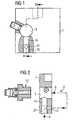
- a part of a bolt outlet device for the supply of successively arranged bolts or Pins represented by blown air through a channel 2 to a stud welder.
- the bolt outlet device has a bearing element 1 with a to the channel 2 coaxial mounting recess 3 for receiving a in Fig. 2nd shown discharge bushing 10 or a supply hose.
- the supply hose is in this case the delivery hose for bolts between the bolt outlet and a welding tool, not shown.
- an air supply line 12 is connected, which is a secondary channel 14 is assigned.
- This secondary channel 14 leads to Fig. 1 and 2 to the Mounting recess 3 and is also through the discharge bushing 10 or closed by the feed tube end.
- the sub-channel 14 has a larger diameter than the air supply line 12th on.
- This air supply line 12 and / or the secondary channel 14 branches of a Main channel 20 of FIG. 2 from. In the position shown in Fig.
- the length of Secondary channel 14 is greater than that of the air supply line 12.
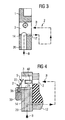
- the air supply line 12 'in the upper region of the secondary channel is arranged and at least partially over its length to the mounting recess 3 is free.
- the bearing element 1 the length of the secondary channel 14 ' smaller than that of the air supply pipe 12 '.
- the air supply line 12 or 12 ' extend parallel or obliquely to the longitudinal axis of the mounting recess 3. In any case, make sure that the flow resistance within the Side channels 14 and 14 'considerably lower than that of the air supply line 12th or 12 'is, in order to open assembly recess 3 no high kinetic energy to act on a located in the channel 2 bolt.
- this aforementioned pneumatic Blow-out lock to combine with a mechanical blow-out:
- a mechanical blocking element 22 is arranged at the end of the channel 2, which protrudes in blocking position S in the mounting recess 3. In open position the channel 2 is released.
- the blocking element 22 is by storing or removing the discharge bush 10 or the feed tube into or out of the mounting recess 3 from the Open position shown in dashed lines in the blocking position S and vice versa transferable.
- the bearing element 1 has a receiving groove 25 for storing the blocking element 22 in the open position, d. H. able in which the Abcommendedbuchse 10 or the feed tube in the mounting recess 3 stored and locked therein.
- the blocking element 22 may be formed as a spring, which is free Mounting recess 3 automatically from the open position to the blocking position moved because of the spring force.
- This spring can end face of the bearing element 1 via a bearing 35 to be attached to a holder 30.
Landscapes
- Engineering & Computer Science (AREA)
- Physics & Mathematics (AREA)
- Plasma & Fusion (AREA)
- Mechanical Engineering (AREA)
- Quick-Acting Or Multi-Walled Pipe Joints (AREA)
- Feeding Of Articles To Conveyors (AREA)
- Glass Compositions (AREA)
- Carbon And Carbon Compounds (AREA)
- Rolling Contact Bearings (AREA)
- Magnetic Bearings And Hydrostatic Bearings (AREA)
- Exhaust Gas After Treatment (AREA)
Abstract
Description
Die Erfindung bezieht sich auf eine Bolzenauslasseinrichtung zur Zuführung von hintereinander angeordneten Bolzen oder Stiften mittels Blasluft durch einen Kanal zu einem Bolzenschweißgerät, wobei die Bolzenauslasseinrichtung ein Lagerelement mit einer zum Kanal koaxialen Montageausnehmung zur Aufnahme einer Abführbuchse oder eines Zuführschlauchs aufweist. Mit Zuführschlauch ist hierbei der Förderschlauch für Bolzen zwischen der Bolzenauslassvorrichtung und dem Schweißwerkzeug definiert.The invention relates to a bolt outlet device for the supply of successively arranged bolts or pins by means of blowing air through a Channel to a stud welder, the bolt outlet a Bearing element with a coaxial to the channel mounting recess for receiving a discharge bush or a supply hose has. With feed hose Here is the delivery hose for bolts between the Bolzenauslassvorrichtung and the welding tool defined.
Als allgemein bekannter Stand der Technik sind bereits derartige Bolzenauslasseinrichtungen bekannt (EP 0 406 645 B1). Diese können beispielsweise mit Sortiereinrichtungen versehen sein, welche jedoch zumeist so gestaltet sind, dass eine Gefährdung des Bedienpersonals vorliegt; sie sind außerdem nicht CE-konform.As a well-known prior art are already such Bolzenauslasseinrichtungen known (EP 0 406 645 B1). These can, for example, with sorting facilities be provided, but which are usually designed so that there is a danger to the operating personnel; they are also not CE compliant.
Bei einer Zuführeinheit der eingangs genannten Art liegt beispielsweise immer dann eine Gefahrensituation vor, wenn ein Zuführschlauch oder eine Abführbuchse aus einer Montagebohrung der Bolzenauslasseinrichtung entfernt und anschließend ein Bolzenfördervorgang absichtlich oder unabsichtlich ausgelöst wird. Der auf direktem Wege herausfliegende Schweißbolzen kann durch seine hohe kinetische Energie zu erheblichen körperlichen Schäden, vorrangig Augenverletzungen, führen.In a feeder unit of the type mentioned, for example, always then a hazardous situation, if a supply hose or a discharge removed from a mounting hole of the bolt outlet and Subsequently, a bolt conveying operation intentionally or unintentionally triggered becomes. The directly outgoing welding stud can by his high kinetic energy leading to significant physical damage, primarily eye injuries, to lead.
Weiterhin ist eine Vorrichtung zum Zuführen von zu verarbeitenden Kleinteilen zu einem Verarbeitungsgerät, insbesondere Bolzenzuführvorrichtung für ein Bolzenschweißgerät bekannt (DE 195 32 937 Cl). Hier findet eine Messvorrichtung zur Überwachung des ordnungsgemäßen Zustandes und/oder der korrekten Verbindung eines Verbindungselements mit einer Zuführeinheit und/oder einer Bolzenzuführvorrichtung für das Bolzenschweißgerät Anwendung. Bei dieser bekannten Konstruktion wird bereits die Aufgabe gelöst, eine Gefährdung von Bedienungspersonen auch dann auszuschließen, wenn der Schlauch bzw. das Verbindungselement beschädigt oder vollkommen zerstört ist. Hier werden elektrische bzw. elektronische Mittel eingesetzt, um die vorgenannte Funktionssicherheit zu erfüllen.Furthermore, a device for supplying small parts to be processed to a processing device, in particular bolt supply device for a Stud welding device known (DE 195 32 937 Cl). Here is a measuring device to monitor the proper condition and / or the correct Connection of a connecting element with a feed unit and / or a stud feeder for the stud welder application. at This known construction already solved the problem, a threat excluded by operators even if the hose or the Connecting element is damaged or completely destroyed. Here are electric or electronic means used to the aforementioned reliability to fulfill.
Der vorliegenden Erfindung liegt entsprechend die Aufgabe zugrunde, eine einfach gestaltete, pneumatisch wirkende Konstruktion zu schaffen, welche die vorgenannte Gefahrenquelle effektiv ausschließt.The present invention is based on the object, a simple designed to create a pneumatic-acting construction, which the effectively excludes the aforementioned source of danger.
Diese Aufgabe wird erfindungsgemäß dadurch gelöst, dass einer mit dem Kanal verbundenen Luftzuführleitung mindestens ein zu der Montageausnehmung führender, durch die Abführbuchse oder durch den Zuführschlauch endseitig verschließbarer Nebenkanal zugeordnet ist. Durch die Schaffung dieses Nebenkanals ergibt sich der Vorteil, dass bei offener Montageausnehmung die kinetische Energie der Blasluft nicht mehr auf einen im Kanal vorliegenden Schweißbolzen einwirkt, so dass dieser nicht aus diesem Kanal herausschießen kann, wodurch die vorgenannte Gefahrenquelle beseitigt ist.This object is achieved in that one with the channel connected air supply at least one leading to the mounting recess, through the discharge bush or through the supply hose end closable Subchannel is assigned. By creating this side channel there is the advantage that with open mounting recess the kinetic Energy of the blown air is no longer on a present in the channel welding stud acts so that it can not shoot out of this channel, causing the aforementioned source of danger has been eliminated.
In vorteilhafter Weiterbildung kann der Nebenkanal einen größeren Durchmesser als die Luftzuführleitung aufweisen. Erfindungsgemäß besteht darüber hinaus die Möglichkeit, dass die Luftzuführleitung und/oder der Nebenkanal von einem Hauptkanal abzweigen. Hierbei kann im Lagerelement die Länge des Nebenkanals entweder größer oder kleiner als die der Luftzuführleitung sein. In an advantageous development, the secondary channel can have a larger diameter have as the air supply line. According to the invention, moreover, the Possibility that the air supply line and / or the secondary channel of a Branch off main channel. Here, in the bearing element, the length of the secondary channel either larger or smaller than that of the air supply line.
Zusätzlich besteht die Möglichkeit, noch eine mechanische Ausblassperre in der Weise zuzufügen, dass endseitig des Kanals ein mechanisches Sperrelement angeordnet ist, welches in Sperrstellung in die Montageausnehmung ragt und in Offenstellung den Kanal freigibt. Das Sperrelement kann hierbei durch Aufnehmen bzw. Entfernen der Abführbuchse oder des Zuführschlauchs in die bzw. aus der Montageausnehmung aus der Offenstellung in die Sperrstellung und umgekehrt überführbar sein.In addition, there is the possibility of still a mechanical Ausblassperre in the Add a way that the end of the channel a mechanical locking element is arranged, which protrudes in the blocking position in the mounting recess and in Open position releases the channel. The blocking element can in this case by recording or removing the discharge bush or the supply hose in or out the mounting recess from the open position to the blocking position and vice versa be transferable.
Vorteilhafte Weiterbildungen ergeben sich aus den Unteransprüchen.Advantageous developments emerge from the subclaims.
Die Erfindung wird nachfolgend anhand von in der Zeichnung dargestellten Ausführungsbeispielen näher beschrieben. In der Zeichnung zeigen:
- Fig. 1
- eine schematische Vorderansicht eines Teils der Bolzenauslasseinrichtung, teils gebrochen;
- Fig. 2
- einen Schnitt gemäß der Linie II-II in Fig. 1 vor dem Einsetzen einer Abführbuchse;
- Fig. 3
- einen Schnitt analog Fig. 2 gemäß einer anderen Ausführungsform der Erfindung;
- Fig. 4
- eine weitere Ausführungsmöglichkeit der Erfindung analog den vorgenannten Schnitten mit Einsatz eines zusätzlichen mechanischen Sperrelements in Schließstellung.
- Fig. 1
- a schematic front view of a part of the bolt outlet, partly broken;
- Fig. 2
- a section along the line II-II in Figure 1 before inserting a discharge bush.
- Fig. 3
- a section analogous to Figure 2 according to another embodiment of the invention.
- Fig. 4
- another embodiment of the invention analogous to the aforementioned sections with the use of an additional mechanical locking element in the closed position.
In den Fig. 1 und 2 ist in einer ersten Ausführungsform ein Teil einer Bolzenauslasseinrichtung
zur Zuführung von hintereinander angeordneten Bolzen oder
Stiften mittels Blasluft durch einen Kanal 2 zu einem Bolzenschweißgerät dargestellt.
Hierbei weist die Bolzenauslasseinrichtung ein Lagerelement 1 mit einer
zum Kanal 2 koaxialen Montageausnehmung 3 zur Aufnahme einer in Fig. 2
dargestellten Abführbuchse 10 oder eines Zuführschlauchs auf.In FIGS. 1 and 2, in a first embodiment, a part of a bolt outlet device
for the supply of successively arranged bolts or
Pins represented by blown air through a
Der Zuführschlauch ist hierbei der Förderschlauch für Bolzen zwischen der Bolzenauslasseinrichtung und einem nicht näher dargestellten Schweißwerkzeug.The supply hose is in this case the delivery hose for bolts between the bolt outlet and a welding tool, not shown.
Mit dem Kanal 2 ist eine Luftzuführleitung 12 verbunden, welcher ein Nebenkanal
14 zugeordnet ist. Dieser Nebenkanal 14 führt nach Fig. 1 und 2 zu der
Montageausnehmung 3 und ist darüber hinaus durch die Abführbuchse 10 oder
durch den Zuführschlauch endseitig verschließbar. Vorteilhafterweise weist hierbei
der Nebenkanal 14 einen größeren Durchmesser als die Luftzuführleitung 12
auf. Diese Luftzuführleitung 12 und/oder der Nebenkanal 14 zweigen von einem
Hauptkanal 20 nach Fig. 2 ab. In der in Fig. 2 dargestellten Position liegt die
Montageausnehmung 3 frei, so dass der Hauptteil des von einer nicht mehr dargestellten
Quelle kommenden Blasluftstroms B über den Kanal 14 und die Montageausnehmung
3 ins Freie tritt und damit einem nicht näher dargestellten, in
dem Kanal 2 befindlichen Bolzen keine kinetische Energie verleiht; dieser Bolzen
kann daher nicht in gefährlicher Weise aus dem Kanal 2 herausschießen und
zu Verletzungen führen.With the
Bei der in Fig. 1 und 2 dargestellten Lösung ist im Lagerelement 1 die Länge des
Nebenkanals 14 größer als die der Luftzufuhrleitung 12. Nach Fig. 3 besteht auch
die Möglichkeit, dass die Luftzuführleitung 12' im oberen Bereich des Nebenkanals
angeordnet ist und zumindest teilweise über ihre Länge zur Montageausnehmung
3 frei liegt. Hier ist im Lagerelement 1 die Länge des Nebenkanals 14'
kleiner als die der Luftzuführleitung 12'. In the solution shown in Fig. 1 and 2 in the bearing element 1, the length of
Bei den vorgenannten Ausführungsformen kann die Luftzuführleitung 12 oder
12' parallel oder schräg zu der Längsachse der Montageausnehmung 3 verlaufen.
In jedem Fall ist sicherzustellen, dass der Strömungswiderstand innerhalb des
Nebenkanals 14 bzw. 14' erheblich geringer als der der Luftzuführleitung 12
bzw. 12' ist, um bei offener Montageausnehmung 3 keine hohe kinetische Energie
auf einen im Kanal 2 befindlichen Bolzen wirken zu lassen.In the aforementioned embodiments, the
Gemäß Fig. 4 besteht auch die Möglichkeit, diese vorgenannte pneumatische
Ausblassperre mit einer mechanischen Ausblassperre zu kombinieren: In diesem
Fall ist endseitig des Kanals 2 ein mechanisches Sperrelement 22 angeordnet,
welches in Sperrstellung S in die Montageausnehmung 3 ragt. In Offenstellung
wird der Kanal 2 freigegeben.According to Fig. 4, it is also possible, this aforementioned pneumatic
Blow-out lock to combine with a mechanical blow-out: In this
Case, a
Das Sperrelement 22 ist durch Einlagern bzw. Entfernen der Abführbuchse 10
oder des Zuführschlauchs in die bzw. aus der Montageausnehmung 3 aus der
gestrichelt dargestellten Offenstellung in die Sperrstellung S und umgekehrt
überführbar. Vorteilhafterweise besitzt das Lagerelement 1 eine Aufnahmenut 25
zum Einlagern des Sperrelements 22 in der Offenstellung, d. h. in der Lage, in
welcher die Abführbuchse 10 oder der Zuführschlauch in der Montageausnehmung
3 eingelagert und darin arretiert ist.The blocking
Das Sperrelement 22 kann als Feder ausgebildet sein, welche sich bei freier
Montageausnehmung 3 selbsttätig aus der Offenstellung in die Sperrstellung
bewegt und zwar infolge der Federkraft. Diese Feder kann stimseitig des Lagerlements
1 über eine Lagerstelle 35 an einem Halter 30 befestigt sein. The blocking
Insgesamt ergibt sich eine pneumatische oder einer pneumatisch-mechanische
Ausblassperre, welche sicherstellt, dass ein im Kanal 2 befindlicher Bolzen 40
nicht in unerwünschter Weise herausschießen kann. Die Erfindung ist sowohl bei
Rotorvereinzelnern als auch bei anderen bereits in der Praxis befindlichen
Kostruktionen einsetzbar.Overall, there is a pneumatic or a pneumatic-mechanical
Ausblassperre, which ensures that a located in the
Claims (12)
- Stud discharge device for feeding studs or pins arranged one behind the other through a channel (2) to a stud welding device by means of blast air (B), the stud discharge device having a bearing element (1) with a mounting opening (3) which is coaxial with the channel (2) and which is provided for receiving a delivery bush (10) or a feed tube, characterised in that at least one secondary channel (14; 14'), which leads to the mounting opening (3) and which can be closed at the end by the delivery bush (10) or by the feed tube, is assigned to an air supply line (12; 12') connected to the channel (2).
- Stud discharge device according to Claim 1, characterised in that the secondary channel 14; 14') has a greater diameter than the air supply line (12; 12').
- Stud discharge device according to Claim 1 or 2, characterised in that the air supply line (12; 12') and/or the secondary channel (14; 14') branch off from a main channel (20).
- Stud discharge device according to one of the preceding claims, characterised in that the length of the secondary channel (14) in the bearing element (1) is greater than that of the air supply line (12) (Fig. 2).
- Stud discharge device according to one of Claims 1 to 3, characterised in that the length of the secondary channel (14') in the bearing element (1) is less than that of the air supply line (12') (Fig. 3).
- Stud discharge device according to Claim 5, characterised in that the air supply line (12') is open to the mounting opening (3) over at least part of its length.
- Stud discharge device according to one of the preceding claims, characterised in that the air supply line (12; 12') runs parallel or obliquely to the longitudinal axis of the mounting opening (3).
- Stud discharge device according to one of the preceding claims, characterised in that the flow resistance inside the secondary channel (14; 14') is considerably less than that in the air supply line (12; 12').
- Stud discharge device according to one of the preceding claims, characterised in that there is arranged at the end of the channel (2) a mechanical blocking element (22) which in the blocking position (S) projects into the mounting opening (3) and in the open position frees the channel (2),
and in that the blocking element (22) can be moved from the open position to the blocking position by removing the delivery bush (10) or the feed tube from the mounting opening (3), or in that the blocking element (22) can be moved from the blocking position to the open position by fitting the delivery bush (10) or the feed tube in the mounting opening (3). - Stud discharge device according to Claim 9, characterised in that the bearing element (1) has a receiving groove (25) for accommodating the blocking element (22) in the open position.
- Stud discharge device according to Claim 9 and 10, characterised in that the blocking element (22) is designed as a spring which moves automatically from the open position to the blocking position (S) when the mounting opening (3) is free.
- Stud discharge device according to Claim 11, characterised in that the spring is fastened to a holder (30) at the front of the bearing element (1) via a bearing (35).
Applications Claiming Priority (3)
| Application Number | Priority Date | Filing Date | Title |
|---|---|---|---|
| DE10015494 | 2000-03-29 | ||
| DE10015494A DE10015494C2 (en) | 2000-03-29 | 2000-03-29 | Stud discharge |
| PCT/DE2001/001137 WO2001072461A1 (en) | 2000-03-29 | 2001-03-23 | Stud discharge device |
Publications (2)
| Publication Number | Publication Date |
|---|---|
| EP1268112A1 EP1268112A1 (en) | 2003-01-02 |
| EP1268112B1 true EP1268112B1 (en) | 2004-08-18 |
Family
ID=7636769
Family Applications (1)
| Application Number | Title | Priority Date | Filing Date |
|---|---|---|---|
| EP01927590A Expired - Lifetime EP1268112B1 (en) | 2000-03-29 | 2001-03-23 | Stud discharge device |
Country Status (4)
| Country | Link |
|---|---|
| EP (1) | EP1268112B1 (en) |
| AT (1) | ATE273767T1 (en) |
| DE (2) | DE10015494C2 (en) |
| WO (1) | WO2001072461A1 (en) |
Cited By (1)
| Publication number | Priority date | Publication date | Assignee | Title |
|---|---|---|---|---|
| EP4570400A1 (en) | 2023-12-11 | 2025-06-18 | Newfrey LLC | Feeding unit and coupling body of a feeding unit comprising a locking element |
Family Cites Families (5)
| Publication number | Priority date | Publication date | Assignee | Title |
|---|---|---|---|---|
| US3583599A (en) * | 1968-10-21 | 1971-06-08 | Trw Inc | Apparatus for feeding a plurality of small parts |
| US3792223A (en) * | 1970-06-01 | 1974-02-12 | Trw Inc | Stud welding tool and stud loading device therefor |
| DE8607260U1 (en) * | 1986-03-15 | 1986-05-07 | OBO Bettermann oHG, 5750 Menden | Sorting device for welding studs |
| DE3922439A1 (en) * | 1989-07-07 | 1991-01-10 | Trw Nelson Bolzenschweiss Tech | DEVICE FOR THE SINGLE FEEDING OF PINS AND / OR PINS ARRANGED BETWEEN GUIDE RAILS |
| DE19532937C1 (en) * | 1995-09-06 | 1996-11-21 | Trw Nelson Bolzenschweisstechn | Appts. for supplying small parts to processing device, esp. bolts to welding machine |
-
2000
- 2000-03-29 DE DE10015494A patent/DE10015494C2/en not_active Expired - Fee Related
-
2001
- 2001-03-23 EP EP01927590A patent/EP1268112B1/en not_active Expired - Lifetime
- 2001-03-23 WO PCT/DE2001/001137 patent/WO2001072461A1/en not_active Ceased
- 2001-03-23 DE DE50103324T patent/DE50103324D1/en not_active Expired - Lifetime
- 2001-03-23 AT AT01927590T patent/ATE273767T1/en not_active IP Right Cessation
Cited By (2)
| Publication number | Priority date | Publication date | Assignee | Title |
|---|---|---|---|---|
| EP4570400A1 (en) | 2023-12-11 | 2025-06-18 | Newfrey LLC | Feeding unit and coupling body of a feeding unit comprising a locking element |
| WO2025125223A1 (en) | 2023-12-11 | 2025-06-19 | Newfrey Llc | Feeding unit and coupling body of a feeding unit comprising a locking element |
Also Published As
| Publication number | Publication date |
|---|---|
| WO2001072461A1 (en) | 2001-10-04 |
| DE10015494C2 (en) | 2002-02-07 |
| DE10015494A1 (en) | 2001-10-11 |
| ATE273767T1 (en) | 2004-09-15 |
| DE50103324D1 (en) | 2004-09-23 |
| EP1268112A1 (en) | 2003-01-02 |
Similar Documents
| Publication | Publication Date | Title |
|---|---|---|
| DE10041984B4 (en) | Device for locking the steering spindle of a vehicle | |
| DE102010039135A1 (en) | Device for holding systems and aircraft or spacecraft | |
| DE202015106360U1 (en) | Milling head unit, milling cutter shank and screw-on milling cutter | |
| EP1268112B1 (en) | Stud discharge device | |
| EP3208567B1 (en) | Sound absorber | |
| AT396079B (en) | ARRANGEMENT FOR A DRILL FOR THE STORAGE AND SUPPORT OF AN INSERT | |
| DE102005019945B4 (en) | Carrier tool for a cutting insert with two cutting edges and cutting insert with two cutting edges | |
| EP3144099A1 (en) | Insert for a drilling machine | |
| EP1280950A1 (en) | Tuck-in selvedge motion for a weaving machine | |
| DE102019111843A1 (en) | Cutting tool | |
| EP3442086B1 (en) | Pipe socket of an electrical installation housing | |
| DE102018103227B4 (en) | valve unit | |
| DE10015495C1 (en) | Rivet ejection device for feeding rivets to welding machine has feed channel for rivets normally blocked at output end by releasable mechanical blocking element | |
| DE102004005427B3 (en) | Wire guide device, e.g. for making springs, has axes guided in long holes, longitudinal center lines of which are not parallel to each other | |
| DE3726507A1 (en) | Thread-splicing device | |
| DE10157787A1 (en) | Method for fitting turning tool to holder has a combination of a conical seat with a cylindrical location for a secure fitting | |
| DE4111845C2 (en) | Device for the longitudinal cutting of tubes, in particular plastic sample tubes | |
| DE20023834U1 (en) | Rivet ejection device for feeding rivets to welding machine has feed channel for rivets normally blocked at output end by releasable mechanical blocking element | |
| DE202005019134U1 (en) | Cutting tool for turning lathe, has clips with two edges running parallel to each other, and profile provided in area of both edges, where profiles of edges in one section are different from profiles of edges in other section | |
| DE9002696U1 (en) | hinge | |
| DE102016105776B4 (en) | Fastening element for a rope holder and rope holder with fastening element | |
| DE102023201106A1 (en) | Wedge clamp and guying device with such a wedge clamp | |
| EP0414672A1 (en) | Linear unit for handling equipment and similar for use in manufacturing industry. | |
| DE102021110462A1 (en) | Rotary cutting tool and holding element for a rotary cutting tool | |
| DE202021103457U1 (en) | Hollow profile and connection arrangement of a hollow profile on a component provided with a threaded hole |
Legal Events
| Date | Code | Title | Description |
|---|---|---|---|
| PUAI | Public reference made under article 153(3) epc to a published international application that has entered the european phase |
Free format text: ORIGINAL CODE: 0009012 |
|
| 17P | Request for examination filed |
Effective date: 20020913 |
|
| AK | Designated contracting states |
Kind code of ref document: A1 Designated state(s): AT BE CH CY DE DK ES FI FR GB GR IE IT LI LU MC NL PT SE TR |
|
| AX | Request for extension of the european patent |
Free format text: AL;LT;LV;MK;RO;SI |
|
| GRAP | Despatch of communication of intention to grant a patent |
Free format text: ORIGINAL CODE: EPIDOSNIGR1 |
|
| GRAS | Grant fee paid |
Free format text: ORIGINAL CODE: EPIDOSNIGR3 |
|
| GRAA | (expected) grant |
Free format text: ORIGINAL CODE: 0009210 |
|
| AK | Designated contracting states |
Kind code of ref document: B1 Designated state(s): AT BE CH CY DE DK ES FI FR GB GR IE IT LI LU MC NL PT SE TR |
|
| PG25 | Lapsed in a contracting state [announced via postgrant information from national office to epo] |
Ref country code: IT Free format text: LAPSE BECAUSE OF FAILURE TO SUBMIT A TRANSLATION OF THE DESCRIPTION OR TO PAY THE FEE WITHIN THE PRESCRIBED TIME-LIMIT;WARNING: LAPSES OF ITALIAN PATENTS WITH EFFECTIVE DATE BEFORE 2007 MAY HAVE OCCURRED AT ANY TIME BEFORE 2007. THE CORRECT EFFECTIVE DATE MAY BE DIFFERENT FROM THE ONE RECORDED. Effective date: 20040818 Ref country code: TR Free format text: LAPSE BECAUSE OF FAILURE TO SUBMIT A TRANSLATION OF THE DESCRIPTION OR TO PAY THE FEE WITHIN THE PRESCRIBED TIME-LIMIT Effective date: 20040818 Ref country code: FI Free format text: LAPSE BECAUSE OF FAILURE TO SUBMIT A TRANSLATION OF THE DESCRIPTION OR TO PAY THE FEE WITHIN THE PRESCRIBED TIME-LIMIT Effective date: 20040818 Ref country code: NL Free format text: LAPSE BECAUSE OF FAILURE TO SUBMIT A TRANSLATION OF THE DESCRIPTION OR TO PAY THE FEE WITHIN THE PRESCRIBED TIME-LIMIT Effective date: 20040818 Ref country code: IE Free format text: LAPSE BECAUSE OF FAILURE TO SUBMIT A TRANSLATION OF THE DESCRIPTION OR TO PAY THE FEE WITHIN THE PRESCRIBED TIME-LIMIT Effective date: 20040818 |
|
| REG | Reference to a national code |
Ref country code: GB Ref legal event code: FG4D Free format text: NOT ENGLISH |
|
| REG | Reference to a national code |
Ref country code: CH Ref legal event code: EP |
|
| REG | Reference to a national code |
Ref country code: IE Ref legal event code: FG4D Free format text: GERMAN |
|
| REF | Corresponds to: |
Ref document number: 50103324 Country of ref document: DE Date of ref document: 20040923 Kind code of ref document: P |
|
| PG25 | Lapsed in a contracting state [announced via postgrant information from national office to epo] |
Ref country code: SE Free format text: LAPSE BECAUSE OF FAILURE TO SUBMIT A TRANSLATION OF THE DESCRIPTION OR TO PAY THE FEE WITHIN THE PRESCRIBED TIME-LIMIT Effective date: 20041118 Ref country code: GR Free format text: LAPSE BECAUSE OF FAILURE TO SUBMIT A TRANSLATION OF THE DESCRIPTION OR TO PAY THE FEE WITHIN THE PRESCRIBED TIME-LIMIT Effective date: 20041118 Ref country code: DK Free format text: LAPSE BECAUSE OF FAILURE TO SUBMIT A TRANSLATION OF THE DESCRIPTION OR TO PAY THE FEE WITHIN THE PRESCRIBED TIME-LIMIT Effective date: 20041118 |
|
| PG25 | Lapsed in a contracting state [announced via postgrant information from national office to epo] |
Ref country code: ES Free format text: LAPSE BECAUSE OF FAILURE TO SUBMIT A TRANSLATION OF THE DESCRIPTION OR TO PAY THE FEE WITHIN THE PRESCRIBED TIME-LIMIT Effective date: 20041129 |
|
| GBT | Gb: translation of ep patent filed (gb section 77(6)(a)/1977) |
Effective date: 20041215 |
|
| LTIE | Lt: invalidation of european patent or patent extension |
Effective date: 20040818 |
|
| NLV1 | Nl: lapsed or annulled due to failure to fulfill the requirements of art. 29p and 29m of the patents act | ||
| PG25 | Lapsed in a contracting state [announced via postgrant information from national office to epo] |
Ref country code: LU Free format text: LAPSE BECAUSE OF NON-PAYMENT OF DUE FEES Effective date: 20050323 Ref country code: AT Free format text: LAPSE BECAUSE OF NON-PAYMENT OF DUE FEES Effective date: 20050323 Ref country code: CY Free format text: LAPSE BECAUSE OF FAILURE TO SUBMIT A TRANSLATION OF THE DESCRIPTION OR TO PAY THE FEE WITHIN THE PRESCRIBED TIME-LIMIT Effective date: 20050323 |
|
| REG | Reference to a national code |
Ref country code: IE Ref legal event code: FD4D |
|
| PG25 | Lapsed in a contracting state [announced via postgrant information from national office to epo] |
Ref country code: BE Free format text: LAPSE BECAUSE OF NON-PAYMENT OF DUE FEES Effective date: 20050331 Ref country code: MC Free format text: LAPSE BECAUSE OF NON-PAYMENT OF DUE FEES Effective date: 20050331 Ref country code: LI Free format text: LAPSE BECAUSE OF NON-PAYMENT OF DUE FEES Effective date: 20050331 Ref country code: CH Free format text: LAPSE BECAUSE OF NON-PAYMENT OF DUE FEES Effective date: 20050331 |
|
| PLBE | No opposition filed within time limit |
Free format text: ORIGINAL CODE: 0009261 |
|
| STAA | Information on the status of an ep patent application or granted ep patent |
Free format text: STATUS: NO OPPOSITION FILED WITHIN TIME LIMIT |
|
| ET | Fr: translation filed | ||
| 26N | No opposition filed |
Effective date: 20050519 |
|
| BERE | Be: lapsed |
Owner name: *NELSON BOLZENSCHWEISS-TECHNIK G.M.B.H. & CO. K.G. Effective date: 20050331 |
|
| REG | Reference to a national code |
Ref country code: CH Ref legal event code: PL |
|
| BERE | Be: lapsed |
Owner name: *NELSON BOLZENSCHWEISS-TECHNIK G.M.B.H. & CO. K.G. Effective date: 20050331 |
|
| PG25 | Lapsed in a contracting state [announced via postgrant information from national office to epo] |
Ref country code: PT Free format text: LAPSE BECAUSE OF NON-PAYMENT OF DUE FEES Effective date: 20050118 |
|
| REG | Reference to a national code |
Ref country code: FR Ref legal event code: PLFP Year of fee payment: 16 |
|
| REG | Reference to a national code |
Ref country code: FR Ref legal event code: PLFP Year of fee payment: 17 |
|
| REG | Reference to a national code |
Ref country code: FR Ref legal event code: PLFP Year of fee payment: 18 |
|
| PGFP | Annual fee paid to national office [announced via postgrant information from national office to epo] |
Ref country code: ES Payment date: 20190506 Year of fee payment: 16 |
|
| REG | Reference to a national code |
Ref country code: DE Ref legal event code: R082 Ref document number: 50103324 Country of ref document: DE Representative=s name: EDER SCHIESCHKE & PARTNER MBB, PATENTANWAELTE, DE Ref country code: DE Ref legal event code: R081 Ref document number: 50103324 Country of ref document: DE Owner name: AVISTUD GMBH, DE Free format text: FORMER OWNER: NELSON BOLZENSCHWEISS-TECHNIK GMBH & CO. KG, 58285 GEVELSBERG, DE Ref country code: DE Ref legal event code: R081 Ref document number: 50103324 Country of ref document: DE Owner name: IVOSTUD GMBH, DE Free format text: FORMER OWNER: NELSON BOLZENSCHWEISS-TECHNIK GMBH & CO. KG, 58285 GEVELSBERG, DE |
|
| REG | Reference to a national code |
Ref country code: GB Ref legal event code: 732E Free format text: REGISTERED BETWEEN 20190718 AND 20190724 |
|
| PGFP | Annual fee paid to national office [announced via postgrant information from national office to epo] |
Ref country code: GB Payment date: 20190404 Year of fee payment: 19 |
|
| REG | Reference to a national code |
Ref country code: DE Ref legal event code: R082 Ref document number: 50103324 Country of ref document: DE Representative=s name: EDER SCHIESCHKE & PARTNER MBB, PATENTANWAELTE, DE Ref country code: DE Ref legal event code: R081 Ref document number: 50103324 Country of ref document: DE Owner name: IVOSTUD GMBH, DE Free format text: FORMER OWNER: AVISTUD GMBH, 58339 BRECKERFELD, DE |
|
| PGFP | Annual fee paid to national office [announced via postgrant information from national office to epo] |
Ref country code: DE Payment date: 20200327 Year of fee payment: 20 |
|
| PG25 | Lapsed in a contracting state [announced via postgrant information from national office to epo] |
Ref country code: FR Free format text: LAPSE BECAUSE OF NON-PAYMENT OF DUE FEES Effective date: 20200331 |
|
| REG | Reference to a national code |
Ref country code: DE Ref legal event code: R071 Ref document number: 50103324 Country of ref document: DE |
|
| GBPC | Gb: european patent ceased through non-payment of renewal fee |
Effective date: 20200323 |
|
| PG25 | Lapsed in a contracting state [announced via postgrant information from national office to epo] |
Ref country code: GB Free format text: LAPSE BECAUSE OF NON-PAYMENT OF DUE FEES Effective date: 20200323 |