EP1268112B1 - Dispositif pour decharger des goujons - Google Patents
Dispositif pour decharger des goujons Download PDFInfo
- Publication number
- EP1268112B1 EP1268112B1 EP01927590A EP01927590A EP1268112B1 EP 1268112 B1 EP1268112 B1 EP 1268112B1 EP 01927590 A EP01927590 A EP 01927590A EP 01927590 A EP01927590 A EP 01927590A EP 1268112 B1 EP1268112 B1 EP 1268112B1
- Authority
- EP
- European Patent Office
- Prior art keywords
- discharge device
- channel
- stud
- air supply
- supply line
- Prior art date
- Legal status (The legal status is an assumption and is not a legal conclusion. Google has not performed a legal analysis and makes no representation as to the accuracy of the status listed.)
- Expired - Lifetime
Links
- 230000000903 blocking effect Effects 0.000 claims description 19
- 238000003466 welding Methods 0.000 claims description 6
- 238000010276 construction Methods 0.000 description 2
- 230000006378 damage Effects 0.000 description 2
- 238000011161 development Methods 0.000 description 2
- 230000018109 developmental process Effects 0.000 description 2
- 208000020564 Eye injury Diseases 0.000 description 1
- 208000027418 Wounds and injury Diseases 0.000 description 1
- 238000007664 blowing Methods 0.000 description 1
- 231100001261 hazardous Toxicity 0.000 description 1
- 208000014674 injury Diseases 0.000 description 1
- 230000001960 triggered effect Effects 0.000 description 1
Images
Classifications
-
- B—PERFORMING OPERATIONS; TRANSPORTING
- B23—MACHINE TOOLS; METAL-WORKING NOT OTHERWISE PROVIDED FOR
- B23K—SOLDERING OR UNSOLDERING; WELDING; CLADDING OR PLATING BY SOLDERING OR WELDING; CUTTING BY APPLYING HEAT LOCALLY, e.g. FLAME CUTTING; WORKING BY LASER BEAM
- B23K9/00—Arc welding or cutting
- B23K9/20—Stud welding
- B23K9/206—Stud welding with automatic stud supply
Definitions
- the invention relates to a bolt outlet device for the supply of successively arranged bolts or pins by means of blowing air through a Channel to a stud welder, the bolt outlet a Bearing element with a coaxial to the channel mounting recess for receiving a discharge bush or a supply hose has.
- feed hose Here is the delivery hose for bolts between the Bolzenauslassvorraum and the welding tool defined.
- a feeder unit of the type mentioned for example, always then a hazardous situation, if a supply hose or a discharge removed from a mounting hole of the bolt outlet and Subsequently, a bolt conveying operation intentionally or unintentionally triggered becomes.
- the directly outgoing welding stud can by his high kinetic energy leading to significant physical damage, primarily eye injuries, to lead.
- a device for supplying small parts to be processed to a processing device in particular bolt supply device for a Stud welding device known (DE 195 32 937 Cl).
- a measuring device to monitor the proper condition and / or the correct Connection of a connecting element with a feed unit and / or a stud feeder for the stud welder application.
- This known construction already solved the problem, a threat excluded by operators even if the hose or the Connecting element is damaged or completely destroyed.
- electric or electronic means used to the aforementioned reliability to fulfill.
- the present invention is based on the object, a simple designed to create a pneumatic-acting construction, which the effectively excludes the aforementioned source of danger.
- This object is achieved in that one with the channel connected air supply at least one leading to the mounting recess, through the discharge bush or through the supply hose end closable Subchannel is assigned.
- the secondary channel can have a larger diameter have as the air supply line. According to the invention, moreover, the Possibility that the air supply line and / or the secondary channel of a Branch off main channel.
- the length of the secondary channel either larger or smaller than that of the air supply line.
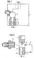
- a part of a bolt outlet device for the supply of successively arranged bolts or Pins represented by blown air through a channel 2 to a stud welder.
- the bolt outlet device has a bearing element 1 with a to the channel 2 coaxial mounting recess 3 for receiving a in Fig. 2nd shown discharge bushing 10 or a supply hose.
- the supply hose is in this case the delivery hose for bolts between the bolt outlet and a welding tool, not shown.
- an air supply line 12 is connected, which is a secondary channel 14 is assigned.
- This secondary channel 14 leads to Fig. 1 and 2 to the Mounting recess 3 and is also through the discharge bushing 10 or closed by the feed tube end.
- the sub-channel 14 has a larger diameter than the air supply line 12th on.
- This air supply line 12 and / or the secondary channel 14 branches of a Main channel 20 of FIG. 2 from. In the position shown in Fig.
- the length of Secondary channel 14 is greater than that of the air supply line 12.
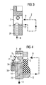
- the air supply line 12 'in the upper region of the secondary channel is arranged and at least partially over its length to the mounting recess 3 is free.
- the bearing element 1 the length of the secondary channel 14 ' smaller than that of the air supply pipe 12 '.
- the air supply line 12 or 12 ' extend parallel or obliquely to the longitudinal axis of the mounting recess 3. In any case, make sure that the flow resistance within the Side channels 14 and 14 'considerably lower than that of the air supply line 12th or 12 'is, in order to open assembly recess 3 no high kinetic energy to act on a located in the channel 2 bolt.
- this aforementioned pneumatic Blow-out lock to combine with a mechanical blow-out:
- a mechanical blocking element 22 is arranged at the end of the channel 2, which protrudes in blocking position S in the mounting recess 3. In open position the channel 2 is released.
- the blocking element 22 is by storing or removing the discharge bush 10 or the feed tube into or out of the mounting recess 3 from the Open position shown in dashed lines in the blocking position S and vice versa transferable.
- the bearing element 1 has a receiving groove 25 for storing the blocking element 22 in the open position, d. H. able in which the Abcommendedbuchse 10 or the feed tube in the mounting recess 3 stored and locked therein.
- the blocking element 22 may be formed as a spring, which is free Mounting recess 3 automatically from the open position to the blocking position moved because of the spring force.
- This spring can end face of the bearing element 1 via a bearing 35 to be attached to a holder 30.
Landscapes
- Engineering & Computer Science (AREA)
- Physics & Mathematics (AREA)
- Plasma & Fusion (AREA)
- Mechanical Engineering (AREA)
- Quick-Acting Or Multi-Walled Pipe Joints (AREA)
- Feeding Of Articles To Conveyors (AREA)
- Rolling Contact Bearings (AREA)
- Magnetic Bearings And Hydrostatic Bearings (AREA)
- Exhaust Gas After Treatment (AREA)
- Carbon And Carbon Compounds (AREA)
- Glass Compositions (AREA)
Claims (12)
- Dispositif de délivrance de goujons pour amener des goujons ou des broches disposées les unes derrière les autres, au moyen d'un air de soufflage (B) à l'intérieur d'un canal (2) jusqu'à un appareil de soudage de goujons, le dispositif de délivrance de goujons possédant un élément de support (1) comportant un évidement de montage (3) qui est coaxial au canal (2) et sert à loger un manchon d'évacuation (10) ou un tuyau d'amenée, caractérisé en ce qu'à une canalisation d'amenée d'air (12;12') reliée au canal (2) est associé au moins un canal secondaire (14; 14') qui aboutit à l'évidement de montage (3) et peut être fermé à son extrémité par le manchon d'évacuation (10) ou par le tuyau d'amenée.
- Dispositif de délivrance de goujons selon la revendication 1, caractérisé en ce que le canal secondaire (14,14') possède un diamètre supérieur à celui de la canalisation d'amenée d'air (12;12').
- Dispositif de délivrance de goujons selon les revendications 1 ou 2, caractérisé en ce que la canalisation d'amenée d'air (12;12') et/ou le canal secondaire (14;14') s'étendent en dérivation à partir d'un canal principal (20).
- Dispositif de délivrance de goujons selon l'une des revendications précédentes, caractérisé en ce que dans l'élément de support (1), la longueur du canal secondaire (14) est supérieure à celle de la canalisation d'amenée d'air (12) (figure 2).
- Dispositif de délivrance de goujons selon l'une des revendications 1 à 3, caractérisé en ce que dans l'élément de support (1), la longueur du canal secondaire (14') est inférieure à celle de la canalisation (12') d'amenée d'air (figure 3).
- Dispositif de délivrance de goujons selon la revendication 5, caractérisé en ce que la canalisation d'amenée d'air (12') est ouverte au moins partiellement sur sa longueur en direction de l'ouverture de montage (3).
- Dispositif de délivrance de goujons selon l'une des revendications précédentes, caractérisé en ce que la canalisation d'amenée d'air (12; 12') est parallèle ou oblique par rapport à l'axe longitudinal de l'évidement de montage (3).
- Dispositif de délivrance de goujons selon l'une des revendications précédentes, caractérisé en ce que la résistance d'écoulement est nettement plus faible à l'intérieur du canal secondaire (14;14') que dans la canalisation d'amenée d'air (12;12').
- Dispositif de délivrance de goujons selon l'une des revendications précédentes, caractérisé en ce que sur le côté d'extrémité du canal (2) est disposé un élément de blocage mécanique (22), qui, dans la position de blocage (S), fait saillie dans l'évidement de montage (3) et, dans la position ouverte, libère le canal (2), et
que l'élément de blocage (22) peut être transféré, par retrait du manchon d'évacuation (10) ou du tuyau d'amenée, à partir de l'ouverture de montage (3), depuis la position ouverte dans la position de blocage ou que l'élément de blocage (22) peut être transféré au moyen du montage du manchon d'évacuation (10) ou du tuyau d'amenée dans l'évidement de montage (3), depuis la position de blocage dans la position ouverte. - Dispositif de délivrance de goujons selon la revendication 9, caractérisé en ce que l'élément de support (1) comporte une rainure de réception (25) utilisée pour l'insertion de l'élément de blocage (22) dans la position ouverte.
- Dispositif de délivrance de goujons selon les revendications 9 et 10, caractérisé en ce que l'élément de blocage (22) est agencé sous la forme d'un ressort, qui se déplace automatiquement de la position ouverte dans la position fermée (S), dans le cas où l'évidement de montage (3) est libre.
- Dispositif de délivrance de goujons selon la revendication 11, caractérisé en ce que le ressort est fixé sur le côté frontal de l'élément de support (1) sur un support (30) par l'intermédiaire d'un point de support (35).
Applications Claiming Priority (3)
| Application Number | Priority Date | Filing Date | Title |
|---|---|---|---|
| DE10015494A DE10015494C2 (de) | 2000-03-29 | 2000-03-29 | Bolzenauslasseinrichtung |
| DE10015494 | 2000-03-29 | ||
| PCT/DE2001/001137 WO2001072461A1 (fr) | 2000-03-29 | 2001-03-23 | Dispositif pour decharger des goujons |
Publications (2)
| Publication Number | Publication Date |
|---|---|
| EP1268112A1 EP1268112A1 (fr) | 2003-01-02 |
| EP1268112B1 true EP1268112B1 (fr) | 2004-08-18 |
Family
ID=7636769
Family Applications (1)
| Application Number | Title | Priority Date | Filing Date |
|---|---|---|---|
| EP01927590A Expired - Lifetime EP1268112B1 (fr) | 2000-03-29 | 2001-03-23 | Dispositif pour decharger des goujons |
Country Status (4)
| Country | Link |
|---|---|
| EP (1) | EP1268112B1 (fr) |
| AT (1) | ATE273767T1 (fr) |
| DE (2) | DE10015494C2 (fr) |
| WO (1) | WO2001072461A1 (fr) |
Cited By (1)
| Publication number | Priority date | Publication date | Assignee | Title |
|---|---|---|---|---|
| EP4570400A1 (fr) | 2023-12-11 | 2025-06-18 | Newfrey LLC | Unité d'alimentation et corps d'accouplement d'une unité d'alimentation comprenant un élément de verrouillage |
Family Cites Families (5)
| Publication number | Priority date | Publication date | Assignee | Title |
|---|---|---|---|---|
| US3583599A (en) * | 1968-10-21 | 1971-06-08 | Trw Inc | Apparatus for feeding a plurality of small parts |
| US3792223A (en) * | 1970-06-01 | 1974-02-12 | Trw Inc | Stud welding tool and stud loading device therefor |
| DE8607260U1 (de) * | 1986-03-15 | 1986-05-07 | OBO Bettermann oHG, 5750 Menden | Sortiervorrichtung für Anschweißbolzen |
| DE3922439A1 (de) * | 1989-07-07 | 1991-01-10 | Trw Nelson Bolzenschweiss Tech | Vorrichtung zur einzelzufuehrung von hintereinander zwischen fuehrungsschienen angeordneten bolzen und/oder stiften |
| DE19532937C1 (de) * | 1995-09-06 | 1996-11-21 | Trw Nelson Bolzenschweisstechn | Vorrichtung zum Zuführen von zu verarbeitenden Kleinteilen zu einem Verarbeitungsgerät, insbesondere Bolzenzuführvorrichtung für ein Bolzenschweißgerät |
-
2000
- 2000-03-29 DE DE10015494A patent/DE10015494C2/de not_active Expired - Fee Related
-
2001
- 2001-03-23 WO PCT/DE2001/001137 patent/WO2001072461A1/fr not_active Ceased
- 2001-03-23 DE DE50103324T patent/DE50103324D1/de not_active Expired - Lifetime
- 2001-03-23 AT AT01927590T patent/ATE273767T1/de not_active IP Right Cessation
- 2001-03-23 EP EP01927590A patent/EP1268112B1/fr not_active Expired - Lifetime
Cited By (2)
| Publication number | Priority date | Publication date | Assignee | Title |
|---|---|---|---|---|
| EP4570400A1 (fr) | 2023-12-11 | 2025-06-18 | Newfrey LLC | Unité d'alimentation et corps d'accouplement d'une unité d'alimentation comprenant un élément de verrouillage |
| WO2025125223A1 (fr) | 2023-12-11 | 2025-06-19 | Newfrey Llc | Unité d'alimentation et corps d'accouplement d'une unité d'alimentation comprenant un élément de verrouillage |
Also Published As
| Publication number | Publication date |
|---|---|
| WO2001072461A1 (fr) | 2001-10-04 |
| ATE273767T1 (de) | 2004-09-15 |
| EP1268112A1 (fr) | 2003-01-02 |
| DE10015494A1 (de) | 2001-10-11 |
| DE10015494C2 (de) | 2002-02-07 |
| DE50103324D1 (de) | 2004-09-23 |
Similar Documents
| Publication | Publication Date | Title |
|---|---|---|
| DE10041984B4 (de) | Vorrichtung zur Verriegelung der Lenkspindel eines Fahrzeuges | |
| DE102010039135B4 (de) | Luft- oder Raumfahrzeug mit einer Vorrichtung zur Halterung von Systemen | |
| EP3170598A1 (fr) | Tête de fraise, tige de fraise et fraise vissable | |
| EP1268112B1 (fr) | Dispositif pour decharger des goujons | |
| EP3208567B1 (fr) | Amortisseur de bruit | |
| AT396079B (de) | Anordnung fuer eine bohrmaschine zur lagerung und abstuetzung eines einsteckendstuecks | |
| DE102005019945B4 (de) | Trägerwerkzeug für eine Schneidplatte mit zwei Schneiden und Schneidplatte mit zwei Schneiden | |
| EP3144099A1 (fr) | Insert pour perceuse | |
| EP1280950A1 (fr) | Dispositif de rentrage de bouts d'un metier a tisser | |
| DE102019111843A1 (de) | Zerspanungswerkzeug | |
| EP3442086B1 (fr) | Manchon de tube pour boîtier d'installation électrique | |
| DE102018103227B4 (de) | Ventileinheit | |
| DE10015495C1 (de) | Bolzenauslasseinrichtung | |
| DE102004005427B3 (de) | Vorrichtung zur Führung von Drähten | |
| DE3726507A1 (de) | Fadenspleissvorrichtung | |
| DE10157787A1 (de) | Werkzeug für die spanabhebende Bearbeitung | |
| DE4111845C2 (de) | Vorrichtung zum Längsauftrennen von Rohren, insbesondere von Probenrohren aus Kunststoff | |
| DE20023834U1 (de) | Bolzenauslasseinrichtung | |
| DE202005019134U1 (de) | Trägerwerkzeug für eine Schneidplatte mit zwei Schneiden und Schneidplatte mit zwei Schneiden | |
| DE9002696U1 (de) | Scharnier | |
| DE102016105776B4 (de) | Befestigungselement für einen Seilhalter und Seilhalter mit Befestigungselement | |
| DE102023201106A1 (de) | Keilabspannklemme sowie Abspannvorrichtung mit einer solchen Keilabspannklemme | |
| EP0414672A1 (fr) | Unite lineaire pour la manutention d'equipement et analogue, pour utilisation dans l'industrie manufacturiere. | |
| DE102021110462A1 (de) | Rotationsschneidwerkzeug sowie Halteelement für ein Rotationsschneidwerkzeug | |
| DE202021103457U1 (de) | Hohlprofil und Verbindungsanordnung eines Hohlprofils an einem mit einer Gewindebohrung versehenen Bauteil |
Legal Events
| Date | Code | Title | Description |
|---|---|---|---|
| PUAI | Public reference made under article 153(3) epc to a published international application that has entered the european phase |
Free format text: ORIGINAL CODE: 0009012 |
|
| 17P | Request for examination filed |
Effective date: 20020913 |
|
| AK | Designated contracting states |
Kind code of ref document: A1 Designated state(s): AT BE CH CY DE DK ES FI FR GB GR IE IT LI LU MC NL PT SE TR |
|
| AX | Request for extension of the european patent |
Free format text: AL;LT;LV;MK;RO;SI |
|
| GRAP | Despatch of communication of intention to grant a patent |
Free format text: ORIGINAL CODE: EPIDOSNIGR1 |
|
| GRAS | Grant fee paid |
Free format text: ORIGINAL CODE: EPIDOSNIGR3 |
|
| GRAA | (expected) grant |
Free format text: ORIGINAL CODE: 0009210 |
|
| AK | Designated contracting states |
Kind code of ref document: B1 Designated state(s): AT BE CH CY DE DK ES FI FR GB GR IE IT LI LU MC NL PT SE TR |
|
| PG25 | Lapsed in a contracting state [announced via postgrant information from national office to epo] |
Ref country code: IT Free format text: LAPSE BECAUSE OF FAILURE TO SUBMIT A TRANSLATION OF THE DESCRIPTION OR TO PAY THE FEE WITHIN THE PRESCRIBED TIME-LIMIT;WARNING: LAPSES OF ITALIAN PATENTS WITH EFFECTIVE DATE BEFORE 2007 MAY HAVE OCCURRED AT ANY TIME BEFORE 2007. THE CORRECT EFFECTIVE DATE MAY BE DIFFERENT FROM THE ONE RECORDED. Effective date: 20040818 Ref country code: TR Free format text: LAPSE BECAUSE OF FAILURE TO SUBMIT A TRANSLATION OF THE DESCRIPTION OR TO PAY THE FEE WITHIN THE PRESCRIBED TIME-LIMIT Effective date: 20040818 Ref country code: FI Free format text: LAPSE BECAUSE OF FAILURE TO SUBMIT A TRANSLATION OF THE DESCRIPTION OR TO PAY THE FEE WITHIN THE PRESCRIBED TIME-LIMIT Effective date: 20040818 Ref country code: NL Free format text: LAPSE BECAUSE OF FAILURE TO SUBMIT A TRANSLATION OF THE DESCRIPTION OR TO PAY THE FEE WITHIN THE PRESCRIBED TIME-LIMIT Effective date: 20040818 Ref country code: IE Free format text: LAPSE BECAUSE OF FAILURE TO SUBMIT A TRANSLATION OF THE DESCRIPTION OR TO PAY THE FEE WITHIN THE PRESCRIBED TIME-LIMIT Effective date: 20040818 |
|
| REG | Reference to a national code |
Ref country code: GB Ref legal event code: FG4D Free format text: NOT ENGLISH |
|
| REG | Reference to a national code |
Ref country code: CH Ref legal event code: EP |
|
| REG | Reference to a national code |
Ref country code: IE Ref legal event code: FG4D Free format text: GERMAN |
|
| REF | Corresponds to: |
Ref document number: 50103324 Country of ref document: DE Date of ref document: 20040923 Kind code of ref document: P |
|
| PG25 | Lapsed in a contracting state [announced via postgrant information from national office to epo] |
Ref country code: SE Free format text: LAPSE BECAUSE OF FAILURE TO SUBMIT A TRANSLATION OF THE DESCRIPTION OR TO PAY THE FEE WITHIN THE PRESCRIBED TIME-LIMIT Effective date: 20041118 Ref country code: GR Free format text: LAPSE BECAUSE OF FAILURE TO SUBMIT A TRANSLATION OF THE DESCRIPTION OR TO PAY THE FEE WITHIN THE PRESCRIBED TIME-LIMIT Effective date: 20041118 Ref country code: DK Free format text: LAPSE BECAUSE OF FAILURE TO SUBMIT A TRANSLATION OF THE DESCRIPTION OR TO PAY THE FEE WITHIN THE PRESCRIBED TIME-LIMIT Effective date: 20041118 |
|
| PG25 | Lapsed in a contracting state [announced via postgrant information from national office to epo] |
Ref country code: ES Free format text: LAPSE BECAUSE OF FAILURE TO SUBMIT A TRANSLATION OF THE DESCRIPTION OR TO PAY THE FEE WITHIN THE PRESCRIBED TIME-LIMIT Effective date: 20041129 |
|
| GBT | Gb: translation of ep patent filed (gb section 77(6)(a)/1977) |
Effective date: 20041215 |
|
| LTIE | Lt: invalidation of european patent or patent extension |
Effective date: 20040818 |
|
| NLV1 | Nl: lapsed or annulled due to failure to fulfill the requirements of art. 29p and 29m of the patents act | ||
| PG25 | Lapsed in a contracting state [announced via postgrant information from national office to epo] |
Ref country code: LU Free format text: LAPSE BECAUSE OF NON-PAYMENT OF DUE FEES Effective date: 20050323 Ref country code: AT Free format text: LAPSE BECAUSE OF NON-PAYMENT OF DUE FEES Effective date: 20050323 Ref country code: CY Free format text: LAPSE BECAUSE OF FAILURE TO SUBMIT A TRANSLATION OF THE DESCRIPTION OR TO PAY THE FEE WITHIN THE PRESCRIBED TIME-LIMIT Effective date: 20050323 |
|
| REG | Reference to a national code |
Ref country code: IE Ref legal event code: FD4D |
|
| PG25 | Lapsed in a contracting state [announced via postgrant information from national office to epo] |
Ref country code: BE Free format text: LAPSE BECAUSE OF NON-PAYMENT OF DUE FEES Effective date: 20050331 Ref country code: MC Free format text: LAPSE BECAUSE OF NON-PAYMENT OF DUE FEES Effective date: 20050331 Ref country code: LI Free format text: LAPSE BECAUSE OF NON-PAYMENT OF DUE FEES Effective date: 20050331 Ref country code: CH Free format text: LAPSE BECAUSE OF NON-PAYMENT OF DUE FEES Effective date: 20050331 |
|
| PLBE | No opposition filed within time limit |
Free format text: ORIGINAL CODE: 0009261 |
|
| STAA | Information on the status of an ep patent application or granted ep patent |
Free format text: STATUS: NO OPPOSITION FILED WITHIN TIME LIMIT |
|
| ET | Fr: translation filed | ||
| 26N | No opposition filed |
Effective date: 20050519 |
|
| BERE | Be: lapsed |
Owner name: *NELSON BOLZENSCHWEISS-TECHNIK G.M.B.H. & CO. K.G. Effective date: 20050331 |
|
| REG | Reference to a national code |
Ref country code: CH Ref legal event code: PL |
|
| BERE | Be: lapsed |
Owner name: *NELSON BOLZENSCHWEISS-TECHNIK G.M.B.H. & CO. K.G. Effective date: 20050331 |
|
| PG25 | Lapsed in a contracting state [announced via postgrant information from national office to epo] |
Ref country code: PT Free format text: LAPSE BECAUSE OF NON-PAYMENT OF DUE FEES Effective date: 20050118 |
|
| REG | Reference to a national code |
Ref country code: FR Ref legal event code: PLFP Year of fee payment: 16 |
|
| REG | Reference to a national code |
Ref country code: FR Ref legal event code: PLFP Year of fee payment: 17 |
|
| REG | Reference to a national code |
Ref country code: FR Ref legal event code: PLFP Year of fee payment: 18 |
|
| PGFP | Annual fee paid to national office [announced via postgrant information from national office to epo] |
Ref country code: ES Payment date: 20190506 Year of fee payment: 16 |
|
| REG | Reference to a national code |
Ref country code: DE Ref legal event code: R082 Ref document number: 50103324 Country of ref document: DE Representative=s name: EDER SCHIESCHKE & PARTNER MBB, PATENTANWAELTE, DE Ref country code: DE Ref legal event code: R081 Ref document number: 50103324 Country of ref document: DE Owner name: AVISTUD GMBH, DE Free format text: FORMER OWNER: NELSON BOLZENSCHWEISS-TECHNIK GMBH & CO. KG, 58285 GEVELSBERG, DE Ref country code: DE Ref legal event code: R081 Ref document number: 50103324 Country of ref document: DE Owner name: IVOSTUD GMBH, DE Free format text: FORMER OWNER: NELSON BOLZENSCHWEISS-TECHNIK GMBH & CO. KG, 58285 GEVELSBERG, DE |
|
| REG | Reference to a national code |
Ref country code: GB Ref legal event code: 732E Free format text: REGISTERED BETWEEN 20190718 AND 20190724 |
|
| PGFP | Annual fee paid to national office [announced via postgrant information from national office to epo] |
Ref country code: GB Payment date: 20190404 Year of fee payment: 19 |
|
| REG | Reference to a national code |
Ref country code: DE Ref legal event code: R082 Ref document number: 50103324 Country of ref document: DE Representative=s name: EDER SCHIESCHKE & PARTNER MBB, PATENTANWAELTE, DE Ref country code: DE Ref legal event code: R081 Ref document number: 50103324 Country of ref document: DE Owner name: IVOSTUD GMBH, DE Free format text: FORMER OWNER: AVISTUD GMBH, 58339 BRECKERFELD, DE |
|
| PGFP | Annual fee paid to national office [announced via postgrant information from national office to epo] |
Ref country code: DE Payment date: 20200327 Year of fee payment: 20 |
|
| PG25 | Lapsed in a contracting state [announced via postgrant information from national office to epo] |
Ref country code: FR Free format text: LAPSE BECAUSE OF NON-PAYMENT OF DUE FEES Effective date: 20200331 |
|
| REG | Reference to a national code |
Ref country code: DE Ref legal event code: R071 Ref document number: 50103324 Country of ref document: DE |
|
| GBPC | Gb: european patent ceased through non-payment of renewal fee |
Effective date: 20200323 |
|
| PG25 | Lapsed in a contracting state [announced via postgrant information from national office to epo] |
Ref country code: GB Free format text: LAPSE BECAUSE OF NON-PAYMENT OF DUE FEES Effective date: 20200323 |