EP1268349B1 - Procede ameliore de nettoyage de l'eau - Google Patents
Procede ameliore de nettoyage de l'eau Download PDFInfo
- Publication number
- EP1268349B1 EP1268349B1 EP01904662A EP01904662A EP1268349B1 EP 1268349 B1 EP1268349 B1 EP 1268349B1 EP 01904662 A EP01904662 A EP 01904662A EP 01904662 A EP01904662 A EP 01904662A EP 1268349 B1 EP1268349 B1 EP 1268349B1
- Authority
- EP
- European Patent Office
- Prior art keywords
- water
- liquid
- oil
- injection
- separator
- Prior art date
- Legal status (The legal status is an assumption and is not a legal conclusion. Google has not performed a legal analysis and makes no representation as to the accuracy of the status listed.)
- Expired - Lifetime
Links
- XLYOFNOQVPJJNP-UHFFFAOYSA-N water Substances O XLYOFNOQVPJJNP-UHFFFAOYSA-N 0.000 title claims abstract description 150
- 238000000034 method Methods 0.000 title claims abstract description 32
- 238000004140 cleaning Methods 0.000 title claims description 18
- 230000008569 process Effects 0.000 title claims description 17
- 239000007788 liquid Substances 0.000 claims abstract description 96
- 229930195733 hydrocarbon Natural products 0.000 claims abstract description 46
- 150000002430 hydrocarbons Chemical class 0.000 claims abstract description 46
- 238000000605 extraction Methods 0.000 claims abstract description 44
- 238000002347 injection Methods 0.000 claims abstract description 43
- 239000007924 injection Substances 0.000 claims abstract description 43
- 230000014759 maintenance of location Effects 0.000 claims abstract description 20
- 239000000203 mixture Substances 0.000 claims abstract description 19
- 239000004215 Carbon black (E152) Substances 0.000 claims abstract description 18
- 238000000926 separation method Methods 0.000 claims description 35
- 239000012071 phase Substances 0.000 claims description 33
- 238000004519 manufacturing process Methods 0.000 claims description 20
- 238000011144 upstream manufacturing Methods 0.000 claims description 11
- 238000012546 transfer Methods 0.000 claims description 8
- 238000009826 distribution Methods 0.000 claims description 5
- 239000007791 liquid phase Substances 0.000 claims description 5
- 239000006185 dispersion Substances 0.000 claims description 4
- 230000003068 static effect Effects 0.000 claims description 4
- 230000008929 regeneration Effects 0.000 claims 1
- 238000011069 regeneration method Methods 0.000 claims 1
- ZZUFCTLCJUWOSV-UHFFFAOYSA-N furosemide Chemical compound C1=C(Cl)C(S(=O)(=O)N)=CC(C(O)=O)=C1NCC1=CC=CO1 ZZUFCTLCJUWOSV-UHFFFAOYSA-N 0.000 abstract 1
- 239000007789 gas Substances 0.000 description 29
- 239000012530 fluid Substances 0.000 description 16
- 125000005575 polycyclic aromatic hydrocarbon group Polymers 0.000 description 15
- 230000000694 effects Effects 0.000 description 10
- 238000012986 modification Methods 0.000 description 8
- 230000004048 modification Effects 0.000 description 8
- 239000012223 aqueous fraction Substances 0.000 description 7
- 239000000243 solution Substances 0.000 description 7
- 239000000126 substance Substances 0.000 description 7
- UHOVQNZJYSORNB-UHFFFAOYSA-N Benzene Chemical compound C1=CC=CC=C1 UHOVQNZJYSORNB-UHFFFAOYSA-N 0.000 description 6
- YXFVVABEGXRONW-UHFFFAOYSA-N Toluene Chemical compound CC1=CC=CC=C1 YXFVVABEGXRONW-UHFFFAOYSA-N 0.000 description 6
- VNWKTOKETHGBQD-UHFFFAOYSA-N methane Chemical compound C VNWKTOKETHGBQD-UHFFFAOYSA-N 0.000 description 6
- 238000002156 mixing Methods 0.000 description 5
- 150000001875 compounds Chemical class 0.000 description 4
- 239000000839 emulsion Substances 0.000 description 4
- 102000003729 Neprilysin Human genes 0.000 description 3
- 108090000028 Neprilysin Proteins 0.000 description 3
- CTQNGGLPUBDAKN-UHFFFAOYSA-N O-Xylene Chemical compound CC1=CC=CC=C1C CTQNGGLPUBDAKN-UHFFFAOYSA-N 0.000 description 3
- 238000013461 design Methods 0.000 description 3
- 230000007613 environmental effect Effects 0.000 description 3
- 238000005188 flotation Methods 0.000 description 3
- 238000012545 processing Methods 0.000 description 3
- 239000008096 xylene Substances 0.000 description 3
- UFWIBTONFRDIAS-UHFFFAOYSA-N Naphthalene Chemical compound C1=CC=CC2=CC=CC=C21 UFWIBTONFRDIAS-UHFFFAOYSA-N 0.000 description 2
- 230000000875 corresponding effect Effects 0.000 description 2
- 238000007872 degassing Methods 0.000 description 2
- 230000006872 improvement Effects 0.000 description 2
- 239000003949 liquefied natural gas Substances 0.000 description 2
- 239000003921 oil Substances 0.000 description 2
- JTJMJGYZQZDUJJ-UHFFFAOYSA-N phencyclidine Chemical class C1CCCCN1C1(C=2C=CC=CC=2)CCCCC1 JTJMJGYZQZDUJJ-UHFFFAOYSA-N 0.000 description 2
- 239000002904 solvent Substances 0.000 description 2
- 238000012360 testing method Methods 0.000 description 2
- 238000010977 unit operation Methods 0.000 description 2
- OTMSDBZUPAUEDD-UHFFFAOYSA-N Ethane Chemical compound CC OTMSDBZUPAUEDD-UHFFFAOYSA-N 0.000 description 1
- 238000010521 absorption reaction Methods 0.000 description 1
- 230000002730 additional effect Effects 0.000 description 1
- 231100000693 bioaccumulation Toxicity 0.000 description 1
- 230000008859 change Effects 0.000 description 1
- 238000007906 compression Methods 0.000 description 1
- 230000006835 compression Effects 0.000 description 1
- 238000001816 cooling Methods 0.000 description 1
- 230000001419 dependent effect Effects 0.000 description 1
- 230000006866 deterioration Effects 0.000 description 1
- 238000001035 drying Methods 0.000 description 1
- 238000005516 engineering process Methods 0.000 description 1
- 238000001704 evaporation Methods 0.000 description 1
- 230000008020 evaporation Effects 0.000 description 1
- 238000002474 experimental method Methods 0.000 description 1
- 230000002349 favourable effect Effects 0.000 description 1
- 238000005194 fractionation Methods 0.000 description 1
- 230000009931 harmful effect Effects 0.000 description 1
- 238000009533 lab test Methods 0.000 description 1
- 239000003345 natural gas Substances 0.000 description 1
- 230000002035 prolonged effect Effects 0.000 description 1
- 238000000746 purification Methods 0.000 description 1
- 230000009467 reduction Effects 0.000 description 1
- 230000001105 regulatory effect Effects 0.000 description 1
- 238000011160 research Methods 0.000 description 1
- 238000001179 sorption measurement Methods 0.000 description 1
Images
Classifications
-
- C—CHEMISTRY; METALLURGY
- C02—TREATMENT OF WATER, WASTE WATER, SEWAGE, OR SLUDGE
- C02F—TREATMENT OF WATER, WASTE WATER, SEWAGE, OR SLUDGE
- C02F1/00—Treatment of water, waste water, or sewage
- C02F1/26—Treatment of water, waste water, or sewage by extraction
-
- C—CHEMISTRY; METALLURGY
- C02—TREATMENT OF WATER, WASTE WATER, SEWAGE, OR SLUDGE
- C02F—TREATMENT OF WATER, WASTE WATER, SEWAGE, OR SLUDGE
- C02F1/00—Treatment of water, waste water, or sewage
- C02F1/38—Treatment of water, waste water, or sewage by centrifugal separation
-
- C—CHEMISTRY; METALLURGY
- C02—TREATMENT OF WATER, WASTE WATER, SEWAGE, OR SLUDGE
- C02F—TREATMENT OF WATER, WASTE WATER, SEWAGE, OR SLUDGE
- C02F2101/00—Nature of the contaminant
- C02F2101/30—Organic compounds
- C02F2101/32—Hydrocarbons, e.g. oil
Definitions
- the invention relates to an improved method for purifying water containing dissolved hydrocarbons and chemicals.
- the improvement implies that some of the most environment hostile, dissolvable components also can be separated. This may be achieved by minor modifications of the existing purification equipment, by using a condensate flow from the production system as extraction medium.
- Hydrocyclones are used for purifying water in a production plant for oil and gas. This technology meets the present cleaning requirements of 40 ppm for free oil in water, most often within good margins. Harmful effects of serious degree on the environment occur rarely at such low concentrations of spillage.
- Hydrocyclones do not remove dissolved hydrocarbons from the water.
- Produced water contains also dissolved components, including aromatics such as benzene, toluene and xylene (BTX), naphthalene, phenantrene (NPD), and polyaromatic hydrocarbons (PAH).
- aromatics such as benzene, toluene and xylene (BTX), naphthalene, phenantrene (NPD), and polyaromatic hydrocarbons (PAH).
- aromatics such as benzene, toluene and xylene (BTX), naphthalene, phenantrene (NPD), and polyaromatic hydrocarbons (PAH).
- BTX benzene
- NPD phenantrene
- PAH polyaromatic hydrocarbons
- liquefied hydrocarbons may be used for extraction of liquefied compounds in water, may be considered as known, even if the hydrocarbon phase is "liquified natural gas".
- PCT/NO97/00060 (WO 98/37941) describes in principle application of "liquefied natural gas" for improving separation of dispersed oil in hydrocyclone based systems.
- a major feature in the Patent Specification is that increase of differences in density between the oil phase and the water phase is credited as providing a major effect.
- the Patent Specification does also specify that dissolved components are removed during the process, but the specification lacks a description on how this may be achieved.
- the present invention relates to a process for removal of dissolved components from produced water in hydrocyclone based systems, and where a suitable extraction fluid may be chosen/produced for the purpose. Emphasis is made with respect to the requirements which must be met in order to make the separation of the dissolved components function.
- a surprising and cost saving element is that extraction fluid may be produced from a condensate phase in the very same production plant, from which the water is produced.
- the present invention relates to an improved method and a system for extraction of fat or oil soluble components, for example PAH, NPD, and/or BTX, from produced water which is separated from an oil and/or gas plant, and where the method is characterised by injection of a liquid comprising hydrocarbons from an oil and/or gas plant in a water flow, said injection liquid having a lower content of the oil dissolved components than original oil phase in equilibrium with the water, where the injection liquid is finely dispersed in the entire water phase and mixture of water/hydrocarbon is given a predetermined retention, thereby allowing mass transfer of the oil soluble components from the water to the injection liquid, where after the injection liquid is separated from the water in a separator, preferably a hydrocyclone, where the injection liquid is adapted to the working range of the separator both with respect to pressure and temperature.
- a separator preferably a hydrocyclone
- the invention relates to a method for extraction of fat or oil soluble components, for example PAH, NPD, and/or BTX, from produced water which is separated from an oil and/or gas plant, characterised in that it comprises the following steps:
- the present invention relates to a system as described above, characterised in that it comprises means for injecting and distributing a liquid in the water, said liquid consisting of hydrocarbons which are separated out in the oil/gas treatment process of the plant and having a lower content of the oil soluble components than the equilibrium concentration against the water, means for giving the hydrocarbon/water mixture a predetermined time of retention parallel with the liquid being held dispersed in the mixture, and a separator for separation of hydrocarbons from the water subsequent to the period of retention.
- the invention relates to a system for cleaning of water in an oil/gas plant for cleaning of oil soluble components, such as PAH, NPD and/or BTX, from extracted water in a well flow, characterised in that it comprises:
- the invention comprises production of an extraction medium directly from the same plant as the water.
- Production of an extraction medium to a suitable composition, pressure and temperature, will otherwise represent a substantial cost or represent a direct limitation.
- condensate fractions which will be suitable for extraction of dissolved aromatics in water, may be extracted. It is demonstrated in experiments that extraction of dissolved aromatics will occur.
- the present invention relates thus to an improved method for purifying water containing dissolved hydrocarbons and chemicals.
- the following improvement having substantial impact on costs related to such processes, exist :
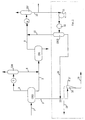
- the extraction process is shown on Figure 1.
- the Figure is made based on an existing production plant for oil and associated gas on the Norwegian Continental shelf.
- the oil contaminated water 2 is separated from oil 3 and gas 4 in a well stream 1 at the inlet separator CD01.
- water containing oil is separated out in a second stage separator, CD2, processed in a separate hydrocyclone unit.
- a typical oil content in the water from such separator is 300 - 2000 ppm. This oil is separated by means of hydrocyclones, till about 20 - 40 ppm, as shown on the Figure.
- water fractions 3 are conducted from the first separator 1 to a second separator where the first fluid fraction is further separated into a second liquid and gas fraction 7, 8.
- the liquid fraction 7 will consist of heavier hydrocarbons, which for example may be conducted into a process plant, while the lighter hydrocarbons in the gas fraction 8 are conducted through a cooler 9 and into a further separator CD7.
- the produced water 2 which escapes out of the separator CD01 will at present let all the dissolved substances escape out with the water, including naphtas, polyaromatic hydrocarbons, benzene, toluene and xylene (BTX). Extraction of these components is achieved by means of the extraction process indicated within the dotted line.
- the fluid fraction 10 is drawn from a fluid separator CD7, as shown on Figure 1 and the required amount is returned to the water flow. Selection of a suitable fluid fraction 10 is important, as described below. Components included in the improved water treatment system according to the invention is shown inside the dotted line while the remaining components 1-CD7 may be included in an existing process plant.
- the pressure of the water fraction may in practice be higher than for the water flow to be treated. An extra pressure surcharge of 5 bar or more is required in order to disperse condensate in the water flow. Liquid fraction 10 from the third separator CD7 in Figure 1 is therefore directed through a pump 11.
- a condensate 10, 14 may be obtained, comprising a relatively low fraction of the water solubles to be removed from the water fraction 2.
- This condensate 10, 14 may consequently be mixed with the water fraction 2 for mass transfer of these components from the water flow to the condensate, so that the remaining water 19 has a reduced content of the water soluble hydrocarbons.
- the water stream 2 is normally warmer than the condensate 14, and one cannot allow the condensate to evaporate subsequent to the mixing.
- the condensate is heated up in a heat exchanger 12 to the temperature required to avoid evaporation when mixed with the water flow.
- Excess of gas is separated in a fourth separator CD10, where after the fluid fraction is mixed into the water phase 2, in the pipeline system 15 upstream of the water purifying hydrocyclone 16.
- the pressure of the condensate 14 may be adjusted to the pressure at which the hydrocyclone 16 operates, by means of a valve or a pump, depending on the pressure at which the water fraction is taken out.
- the temperature of the liquid fraction should be adjusted by means of a heat exchanger, if it otherwise may be formed free gas when mixed with produced water. Excess of gas will then have to be separated within a separate separator. Both these modifications may be achieved by means of the referenced pump 11, separator CD10 and the heat exchanger 12. If gas is not formed when the condensate 10, 14 is mixed with the water phase, then it is unnecessary to install heat exchanger and separator.
- CD01 is a three phase separator which separates oil, water and gas as separate phases.
- the Figure also shows the use of a gas scrubber CD8 which also separates out a liquid fraction which may be considered used as an extraction medium.
- the invention is best suited to be arranged upstream of separation equipment for oil containing water at a pressure close to the operation pressure for upstream three phase separator.
- a filter coalescer will in certain cases be applied as separator at high pressure, as an alternative to a hydrocyclone, e.g. if problems with stable emulsions are experienced.
- the invention is also suitable for other types of processes, where aromatics are extracted by application of hydrocarbons. This applies for instant to counter flow or parallel flow liquid/liquid extraction processes.
- Hydrocarbon reject and excessive condensate may be reintroduced into the process plant , e.g. in front of the second or the third separator CD2, CD7, in order to purify the water soluble hydrocarbons and for reintroduction into the system.
- the process is suitable for extracting fat dissolvent chemicals from produced water. This is due to the fact that fat dissolvent chemicals also will be dissolved and extracted in a condensate fraction.
- Some of the bio accumulative compounds are characterised in that they are fat dissolvable and for this purpose, the described extraction process is well suited.
- Condensate fractions from a production plant are often suitable since they contain a small amount of PAH and NPD and moderate amounts of BTX. Separation occurs normally for compression and drying equipment at 30 - 40 °C, and pressure of 5 - 45 bar. Condensate which is separated out at a higher pressure has a tendency to evaporate when coming into contact with hot produced water. There is certain characteristics which have to be satisfied for a suitable liquid fraction:
- the condensate 10, 14 to be injected into the water flood should have a mole weight of 50 -100 and a bobble point pressure at the hydrocarbon/water mixture which is lower than the operational pressure in the separator and where the content of the oil soluble components is lower than 50% of the equilibrium concentration with the components in the liquid phase.
- BTX is substantially more volatile components than PAH.
- a liquid fraction is separated out in a gas processing plant which may contain sufficient BTX to avoid separation of substantial extra volume at contact with produced water.
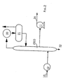
- the fourth separator CD10 shown as a known rectificator, which provides possibilities to take out a liquid fraction with a very low BTX and PAH content.
- the liquid fraction fades in a step.
- Light components will be stripped off at the top of the column, preferably methane and ethane.
- the light components are cooled and separated in a condenser 20, or a separator 21 respectively, where the liquid fraction from the separator 21 is transferred back to the column.
- the residual product in the column will contain less volatile components which may be drained off at the bottom level 22, while one at suitable level in the column will find a suitable concentration of lighter components which is transferred to the pump 11.
- a stripper or a fractionation means is available, and a suitable liquid fraction may then be drawn off directly from the process equipment.
- Water from a production plant for oil and gas has generally a temperature of 50 - 100 °C.
- Light liquid fractions consisting of hydrocarbons will at such high temperature provide good mass transfer with the water phase. It is mainly viscosity and diffusibility which affects the mass transfer.
- Diffusibility may be increased radically if one operates close to the critical point for the hydrocarbon phase. There exists no basis for supercritical conditions being required in order to succeed with this type of extraction process. Supercritical conditions of the hydrocarbon phase provide reduced requirements to area of contact and time of contact between the phases.
- Figure 1 shows a three phase separator CD01 which separates out oil, water and gas as separate phases.
- Table 1 shows concentration of xylene and a more heavy aromatics in the oil phase from three phase separator CD01, in a liquid fraction from an oil scrubber CD8 and in a liquid fraction which is taken out from a liquid separator in the recompression system, respectively. Condensate from two other scrubbers CD5, CD6 (not shown) in the plant are also included for the purpose of comparison.
- the concentration of the aromatics must be substantially lower than in the oil phase from which produced water is separated from. It can be seen that CD7 generally has the lowest concentration of all the groups of aromatics. CD8 has nearly as good concentration, but produces degassing. This means that such condensate must be heated up and gas is separated for injection. This is fully possible, but results in a more expensive solution. Theoretical obtainable separation at equilibrium, CD7 - condensate. Parameter Water, prior to Water, subseq. to Condensate Deg.
- the table shows maximum degree of cleaning if equilibrium is achieved. It is achieved a degree of cleaning of 80 - 90% for PAH in laboratory. Substantially lower degree of cleaning is achieved for BTX since the starting level for BTX in condensate phase is too high. If condensate from CD6 is used, the degree of cleaning for BTX will decrease to 35.5%.
- condensate from CD7 and CD8 are the ones which best satisfies the criteria of selection.
- Condensate from CD5 and CD6 is not suitable, since separation of BTX is too low.
- the volume of condensate from CD5 is also too low to perform a satisfactory separation.
- Results from research show that produced water contains large amounts of droplets of oil/condensate.
- a substantial part of the dispersed hydrocarbons may have a characteristic droplet size of 10 microns or less.
- Hydrocyclones used in hydrocyclone plants shall according to suppliers specification not be able to remove so small droplets. A limit of approximately 20 microns for the range of use is commonly set.
Landscapes
- Chemical & Material Sciences (AREA)
- Engineering & Computer Science (AREA)
- Organic Chemistry (AREA)
- Life Sciences & Earth Sciences (AREA)
- Hydrology & Water Resources (AREA)
- Environmental & Geological Engineering (AREA)
- Water Supply & Treatment (AREA)
- Analytical Chemistry (AREA)
- Mechanical Engineering (AREA)
- Production Of Liquid Hydrocarbon Mixture For Refining Petroleum (AREA)
- Organic Low-Molecular-Weight Compounds And Preparation Thereof (AREA)
- Treatment Of Water By Ion Exchange (AREA)
- Extraction Or Liquid Replacement (AREA)
- Cleaning Or Drying Semiconductors (AREA)
- Processing Of Solid Wastes (AREA)
- Fats And Perfumes (AREA)
- Removal Of Specific Substances (AREA)
- Edible Oils And Fats (AREA)
Claims (15)
- Procédé pour l'extraction de composants solubles dans des graisses ou huiles, par exemple les PAH, NPD et/ou BTX, d'eau de production qui est séparée d'une installation pétrolière et/ou gazière, caractérisé en ce qu'il comprend les étapes suivantes :séparation d'un liquide constitué d'hydrocarbures provenant de l'installation pétrolière et/ou gazière, ledit liquide présentant une teneur en les composants susmentionnés inférieure à la phase huileuse initiale en équilibre avec l'eau,adaptation de la température du liquide à la température de l'eau et adaptation de la pression de bulle à la pression de l'eau,injection du liquide dans le flux d'eau et pulvérisation du liquide dans toute la phase aqueuse et dans le mélange d'eau et d'hydrocarbures,le liquide injecté disposant d'un temps d'exposition prédéterminé dans le mélange, ce qui permet ainsi le transfert de masse des composants solubles dans des graisses ou huiles de l'eau vers le liquide d'injection, etséparation du liquide d'injection de l'eau dans un séparateur, de préférence un hydrocyclone.
- Procédé selon la revendication 1, caractérisé en ce que le liquide est finement distribué au moyen d'une injection au travers d'une buse et/ou distribué dans tout le volume du liquide au moyen d'un mélangeur statique afin de maximiser la surface de contact entre l'eau et le liquide et par conséquent le transfert de masse des composants dissous dans l'eau du liquide d'injection.
- Procédé selon la revendication 1, caractérisé en ce que le temps d'exposition nécessaire au mélange d'eau et d'hydrocarbures présentant un débit valable est obtenu dans le système de conduites situé entre le point d'injection et le séparateur, en plaçant le point d'injection à une distance suffisamment en amont du séparateur.
- Procédé selon la revendication 1, caractérisé en ce que le temps d'exposition entre l'injection du liquide et la séparation du mélange d'hydrocarbures et d'eau est supérieur à 0,3 s.
- Procédé selon la revendication 1, caractérisé en ce que l'eau est séparée d'un flux de pétrole d'une installation de production de pétrole et/ou de gaz, et en ce que le liquide d'injection est constitué d'un condensat qui est extrait d'une manière connue du processus de production de pétrole/gaz de l'installation de production.
- Procédé selon la revendication 1, caractérisé en ce que le liquide d'injection présente une masse molaire de 50-100, a une pression de bulle à la température du mélange d'hydrocarbures et d'eau qui est inférieure à la pression de fonctionnement du séparateur, la teneur en composants solubles dans des huiles étant inférieure à 50% de la concentration à l'équilibre des composants en phase liquide.
- Procédé selon la revendication 1, caractérisé en ce qu'une partie du liquide d'injection est recyclée afin d'obtenir un meilleur degré d'équilibre et d'utilisation du liquide d'injection et/ou en ce que le liquide d'injection est régénéré.
- Procédé selon la revendication 1, caractérisé en ce qu'un coalesceur de filtration est utilisé comme séparateur approprié aux pressions dépassant le fonctionnement atmosphérique.
- Système de nettoyage d'eau dans une installation pétrolière/gazière pour éliminer des composants solubles dans des huiles, tels que les PAH, NPD et/ou BTX, de l'eau extraite d'un flux de puits, caractérisé en ce qu'il comprend :un ou plusieurs séparateurs pour la séparation d'un liquide constitué d'hydrocarbures, présentant une teneur en composants solubles dans des huiles inférieure à la concentration à l'équilibre par rapport à l'eau, de l'installation pétrolière/gazière,un moyen d'adaptation relié au(x) séparateur(s) pour adapter la température du liquide à la température de l'eau et adapter la pression de bulle du liquide à la pression de l'eau,un moyen d'injection relié au moyen d'adaptation pour l'injection et la distribution du liquide dans l'eau,un moyen de rétention, par exemple un tronçon de conduite ou une chambre, pour la rétention du mélange de liquide et d'eau alors que le liquide est maintenu en dispersion dans le mélange, etun séparateur relié au moyen de rétention, de préférence un hydrocyclone, pour séparer le liquide de l'eau à la fin du temps de rétention.
- Système selon la revendication 9, caractérisé en ce qu'il comprend un moyen d'injection, par exemple une buse ou un mélangeur statique pour disperser finement le liquide dans l'eau par injection, afin de maximiser la surface de contact entre l'eau et le liquide et obtenir ainsi un transfert de masse des composants dissous dans l'eau vers le liquide d'injection.
- Système selon la revendication 10, caractérisé en ce que le moyen d'injection est disposé en amont du flux d'eau à une distance prédéterminée du séparateur afin d'obtenir le temps de rétention nécessaire au mélange d'eau et d'hydrocarbures au débit applicable.
- Système selon la revendication 11, caractérisé en ce que la distance est choisie de manière telle que le temps de rétention entre l'injection du liquide et la séparation du mélange d'hydrocarbures et d'eau soit supérieur à 0,3 s.
- Système selon la revendication 9, caractérisé en ce que le système comprend un moyen de séparation de l'eau d'un flux de puits d'une installation de production de pétrole et/ou gaz, et un moyen pour extraire d'une manière connue le condensat du processus de production de pétrole/gaz de l'installation de production afin de former le liquide d'injection.
- Système selon la revendication 9, caractérisé en ce que le système comprend un moyen pour recycler une partie du liquide d'injection afin d'obtenir un meilleur degré d'équilibre et d'utilisation du liquide d'injection et/ou régénérer le liquide d'injection.
- Système selon la revendication 9, caractérisé en ce qu'il comprend un coalesceur de filtration utilisé comme séparateur pour des pressions dépassant les fonctionnements atmosphériques.
Applications Claiming Priority (3)
| Application Number | Priority Date | Filing Date | Title |
|---|---|---|---|
| NO20000617 | 2000-02-08 | ||
| NO20000617A NO312506B2 (no) | 2000-02-08 | 2000-02-08 | Fremgangsmate og vannrenseanlegg for ekstraksjon av fett eller oljeloselige komponenter fra vann i en bronnstrom |
| PCT/NO2001/000041 WO2001058813A1 (fr) | 2000-02-08 | 2001-02-06 | Procede ameliore de nettoyage de l'eau |
Publications (2)
| Publication Number | Publication Date |
|---|---|
| EP1268349A1 EP1268349A1 (fr) | 2003-01-02 |
| EP1268349B1 true EP1268349B1 (fr) | 2005-12-21 |
Family
ID=19910702
Family Applications (1)
| Application Number | Title | Priority Date | Filing Date |
|---|---|---|---|
| EP01904662A Expired - Lifetime EP1268349B1 (fr) | 2000-02-08 | 2001-02-06 | Procede ameliore de nettoyage de l'eau |
Country Status (10)
| Country | Link |
|---|---|
| US (1) | US6875358B2 (fr) |
| EP (1) | EP1268349B1 (fr) |
| AT (1) | ATE313515T1 (fr) |
| AU (1) | AU2001232497A1 (fr) |
| BR (1) | BR0108171B1 (fr) |
| DE (1) | DE60116070D1 (fr) |
| DK (1) | DK1268349T3 (fr) |
| MX (1) | MXPA02007544A (fr) |
| NO (1) | NO312506B2 (fr) |
| WO (1) | WO2001058813A1 (fr) |
Families Citing this family (11)
| Publication number | Priority date | Publication date | Assignee | Title |
|---|---|---|---|---|
| US7008516B2 (en) * | 2001-09-28 | 2006-03-07 | Yoshinobu Kozuka | Method and apparatus for desalinating and concentrating sea water, desalinated deep water and concentrated deep water |
| CA2400258C (fr) * | 2002-09-19 | 2005-01-11 | Suncor Energy Inc. | Separateur de mousse bitumineuse a plaques inclinees et methode de traitement d'hydrocarbures a l'aide d'un cyclone separateur |
| US7736501B2 (en) * | 2002-09-19 | 2010-06-15 | Suncor Energy Inc. | System and process for concentrating hydrocarbons in a bitumen feed |
| US7906023B2 (en) * | 2005-01-25 | 2011-03-15 | Pss Acquisitionco Llc | Wastewater treatment method and apparatus |
| EP2067749A1 (fr) * | 2007-11-29 | 2009-06-10 | Total Petrochemicals France | Procédé pour la purification d'une phase aqueuse contenant des polyaromatiques |
| AU2010274399A1 (en) * | 2009-07-22 | 2012-02-09 | Issei Co., Ltd. | Method for treatment of liquid waste of coating agent |
| US20110062722A1 (en) * | 2009-09-16 | 2011-03-17 | Greatpoint Energy, Inc. | Integrated hydromethanation combined cycle process |
| CA2689021C (fr) | 2009-12-23 | 2015-03-03 | Thomas Charles Hann | Appareil et procede de regulation de debit par le truchement d'une caisse aspirante |
| US20140215903A1 (en) * | 2010-09-21 | 2014-08-07 | Steven Daniel DOIG | Process for separation of a mixture containing a microbial oil and microbial substance |
| WO2013156535A1 (fr) * | 2012-04-17 | 2013-10-24 | Statoil Canada Limited | Procédé de purification de l'eau visant à en éliminer les hydrocarbures |
| GB2501261A (en) * | 2012-04-17 | 2013-10-23 | Statoil Canada Ltd | A method of cleaning water to remove hydrocarbon |
Family Cites Families (15)
| Publication number | Priority date | Publication date | Assignee | Title |
|---|---|---|---|---|
| US2109157A (en) * | 1936-02-04 | 1938-02-22 | Shell Dev | Solvent extraction process |
| US4340076A (en) * | 1979-02-27 | 1982-07-20 | General Technology Applications, Inc. | Dissolving polymers in compatible liquids and uses thereof |
| US4221659A (en) | 1979-03-28 | 1980-09-09 | E. I. Du Pont De Nemours And Company | Process for reducing dichlorobutene contamination in aqueous plant wastes |
| JPS58131104A (ja) | 1982-02-01 | 1983-08-04 | Nippon Steel Chem Co Ltd | 蒸留装置のリボイラ−の洗浄方法 |
| US4401570A (en) | 1982-05-26 | 1983-08-30 | Shell Oil Company | Removal of organic contaminants from waste water |
| WO1988009698A1 (fr) * | 1987-06-10 | 1988-12-15 | Conoco Specialty Products Inc. | Separateur de liquide |
| US4874528A (en) * | 1988-07-18 | 1989-10-17 | General Technology Applications, Inc. | Method for treating dispersions of oleophilic liquids and water |
| US5302294A (en) * | 1991-05-02 | 1994-04-12 | Conoco Specialty Products, Inc. | Separation system employing degassing separators and hydroglyclones |
| RU2022609C1 (ru) | 1991-09-18 | 1994-11-15 | Пятибратов Юрий Петрович | Способ разделения водомасляной эмульсии |
| US5236590A (en) * | 1991-11-21 | 1993-08-17 | Chevron Research And Technology Company | Process for removing dissolved organics from aqueous compositions |
| US5364532A (en) | 1992-09-03 | 1994-11-15 | Petrolite Corporation | Method of removing water soluble organics from oil process water |
| US5853592A (en) * | 1992-09-03 | 1998-12-29 | Baker Hughes Incorporated | Method of removing water soluble organics from oil process water with an organic acid and a mineral acid having a plurality of pKa's |
| NO305346B1 (no) | 1995-08-31 | 1999-05-18 | Tour As C | FremgangsmÕte ved rensing av hydrokarboner |
| FR2738574B1 (fr) * | 1995-09-12 | 1997-11-21 | Total Raffinage Distribution | Procede et dispositif d'extraction des composes aromatiques contenus dans une charge d'hydrocarbures |
| US6077433A (en) | 1997-02-28 | 2000-06-20 | Cagniard De La Tour As | Process for simultaneous extraction of dispersed and dissolved hydrocarbon contaminants from water |
-
2000
- 2000-02-08 NO NO20000617A patent/NO312506B2/no not_active IP Right Cessation
-
2001
- 2001-02-06 MX MXPA02007544A patent/MXPA02007544A/es active IP Right Grant
- 2001-02-06 WO PCT/NO2001/000041 patent/WO2001058813A1/fr not_active Ceased
- 2001-02-06 US US10/203,095 patent/US6875358B2/en not_active Expired - Fee Related
- 2001-02-06 BR BRPI0108171-3A patent/BR0108171B1/pt not_active IP Right Cessation
- 2001-02-06 EP EP01904662A patent/EP1268349B1/fr not_active Expired - Lifetime
- 2001-02-06 DE DE60116070T patent/DE60116070D1/de not_active Expired - Lifetime
- 2001-02-06 AT AT01904662T patent/ATE313515T1/de not_active IP Right Cessation
- 2001-02-06 DK DK01904662T patent/DK1268349T3/da active
- 2001-02-06 AU AU2001232497A patent/AU2001232497A1/en not_active Abandoned
Also Published As
| Publication number | Publication date |
|---|---|
| NO20000617L (no) | 2001-08-09 |
| US20030127387A1 (en) | 2003-07-10 |
| MXPA02007544A (es) | 2002-12-13 |
| US6875358B2 (en) | 2005-04-05 |
| NO312506B1 (no) | 2002-05-21 |
| EP1268349A1 (fr) | 2003-01-02 |
| AU2001232497A1 (en) | 2001-08-20 |
| NO20000617D0 (no) | 2000-02-08 |
| DE60116070D1 (de) | 2006-01-26 |
| BR0108171B1 (pt) | 2010-02-09 |
| DK1268349T3 (da) | 2006-05-01 |
| ATE313515T1 (de) | 2006-01-15 |
| BR0108171A (pt) | 2003-01-21 |
| NO312506B2 (no) | 2002-05-21 |
| WO2001058813A1 (fr) | 2001-08-16 |
Similar Documents
| Publication | Publication Date | Title |
|---|---|---|
| CA2698049C (fr) | Systeme et procede de purification d'un flux aqueux | |
| US11193071B2 (en) | Simultaneous crude oil dehydration, desalting, sweetening, and stabilization | |
| EP3257565B1 (fr) | Procédé et appareil de renforcement de fonctions couplées de séparation pétrole-eau et de dessalage dans un séparateur à froid basse pression | |
| CA3001479C (fr) | Deshydratation sous-marine compacte | |
| EP1268349B1 (fr) | Procede ameliore de nettoyage de l'eau | |
| US10913013B2 (en) | System and method to process effluent brine and interface rag from an oil dehydration/desalting system | |
| US7097761B2 (en) | Method of removing water and contaminants from crude oil containing same | |
| WO2012065243A1 (fr) | Procédé et appareil pour le retrait d'oxygène à partir d'eau de mer | |
| CA2946136C (fr) | Procede et appareil pour recuperer des huiles synthetiques a partir de flux d'huiles composites | |
| AU2006310156B2 (en) | A method of separating a mixture, and a plant for separating a mixture comprising water, oil and gas | |
| US20020079248A1 (en) | Method of removing water and contaminants from crude oil containing same | |
| CN204447409U (zh) | 一种强化冷低压分离器中油水分离及耦合除盐装置 | |
| CA2349872C (fr) | Methode et dispositif permettant d'enlever les contaminants moussants des solvants de traitement d'hydrocarbures | |
| CN105246575A (zh) | 用于从气体混合物和液体混合物中回收二甲醚的系统和方法 | |
| Soliman et al. | Innovative Integrated and Compact Gas Oil Separation Plant for Upstream Surface Facilities | |
| Lyddon et al. | Analysis of various flow schemes for sweetening with amines | |
| CA2364831C (fr) | Methode pour eliminer l'eau et les contaminants du petrole brut | |
| CN109399888B (zh) | 含油污泥的连续脱盐脱水方法和装置 | |
| EP2089131B1 (fr) | Procédé et dispositif de séparation d'un fluide liquide par séparation centrifuge et évaporation | |
| CA3073593A1 (fr) | Appareil et procede pour une installation de traitement | |
| CA1302937B (fr) | Purificateur de petrole brut | |
| WO2017177015A1 (fr) | Procédé pour traiter des fluides contaminés |
Legal Events
| Date | Code | Title | Description |
|---|---|---|---|
| PUAI | Public reference made under article 153(3) epc to a published international application that has entered the european phase |
Free format text: ORIGINAL CODE: 0009012 |
|
| 17P | Request for examination filed |
Effective date: 20020909 |
|
| AK | Designated contracting states |
Kind code of ref document: A1 Designated state(s): AT BE CH CY DE DK ES FI FR GB GR IE IT LI LU MC NL PT SE TR |
|
| AX | Request for extension of the european patent |
Free format text: AL;LT;LV;MK;RO;SI |
|
| 17Q | First examination report despatched |
Effective date: 20040226 |
|
| GRAP | Despatch of communication of intention to grant a patent |
Free format text: ORIGINAL CODE: EPIDOSNIGR1 |
|
| GRAS | Grant fee paid |
Free format text: ORIGINAL CODE: EPIDOSNIGR3 |
|
| GRAA | (expected) grant |
Free format text: ORIGINAL CODE: 0009210 |
|
| AK | Designated contracting states |
Kind code of ref document: B1 Designated state(s): AT BE CH CY DE DK ES FI FR GB GR IE IT LI LU MC NL PT SE TR |
|
| PG25 | Lapsed in a contracting state [announced via postgrant information from national office to epo] |
Ref country code: BE Free format text: LAPSE BECAUSE OF FAILURE TO SUBMIT A TRANSLATION OF THE DESCRIPTION OR TO PAY THE FEE WITHIN THE PRESCRIBED TIME-LIMIT Effective date: 20051221 Ref country code: LI Free format text: LAPSE BECAUSE OF FAILURE TO SUBMIT A TRANSLATION OF THE DESCRIPTION OR TO PAY THE FEE WITHIN THE PRESCRIBED TIME-LIMIT Effective date: 20051221 Ref country code: CH Free format text: LAPSE BECAUSE OF FAILURE TO SUBMIT A TRANSLATION OF THE DESCRIPTION OR TO PAY THE FEE WITHIN THE PRESCRIBED TIME-LIMIT Effective date: 20051221 Ref country code: AT Free format text: LAPSE BECAUSE OF FAILURE TO SUBMIT A TRANSLATION OF THE DESCRIPTION OR TO PAY THE FEE WITHIN THE PRESCRIBED TIME-LIMIT Effective date: 20051221 Ref country code: FI Free format text: LAPSE BECAUSE OF FAILURE TO SUBMIT A TRANSLATION OF THE DESCRIPTION OR TO PAY THE FEE WITHIN THE PRESCRIBED TIME-LIMIT Effective date: 20051221 |
|
| REG | Reference to a national code |
Ref country code: GB Ref legal event code: FG4D |
|
| REG | Reference to a national code |
Ref country code: CH Ref legal event code: EP |
|
| REG | Reference to a national code |
Ref country code: IE Ref legal event code: FG4D |
|
| REF | Corresponds to: |
Ref document number: 60116070 Country of ref document: DE Date of ref document: 20060126 Kind code of ref document: P |
|
| PG25 | Lapsed in a contracting state [announced via postgrant information from national office to epo] |
Ref country code: IE Free format text: LAPSE BECAUSE OF NON-PAYMENT OF DUE FEES Effective date: 20060206 |
|
| PG25 | Lapsed in a contracting state [announced via postgrant information from national office to epo] |
Ref country code: LU Free format text: LAPSE BECAUSE OF NON-PAYMENT OF DUE FEES Effective date: 20060228 Ref country code: MC Free format text: LAPSE BECAUSE OF NON-PAYMENT OF DUE FEES Effective date: 20060228 |
|
| PG25 | Lapsed in a contracting state [announced via postgrant information from national office to epo] |
Ref country code: GR Free format text: LAPSE BECAUSE OF FAILURE TO SUBMIT A TRANSLATION OF THE DESCRIPTION OR TO PAY THE FEE WITHIN THE PRESCRIBED TIME-LIMIT Effective date: 20060321 Ref country code: SE Free format text: LAPSE BECAUSE OF FAILURE TO SUBMIT A TRANSLATION OF THE DESCRIPTION OR TO PAY THE FEE WITHIN THE PRESCRIBED TIME-LIMIT Effective date: 20060321 |
|
| PG25 | Lapsed in a contracting state [announced via postgrant information from national office to epo] |
Ref country code: DE Free format text: LAPSE BECAUSE OF FAILURE TO SUBMIT A TRANSLATION OF THE DESCRIPTION OR TO PAY THE FEE WITHIN THE PRESCRIBED TIME-LIMIT Effective date: 20060322 |
|
| PG25 | Lapsed in a contracting state [announced via postgrant information from national office to epo] |
Ref country code: ES Free format text: LAPSE BECAUSE OF FAILURE TO SUBMIT A TRANSLATION OF THE DESCRIPTION OR TO PAY THE FEE WITHIN THE PRESCRIBED TIME-LIMIT Effective date: 20060401 |
|
| REG | Reference to a national code |
Ref country code: DK Ref legal event code: T3 |
|
| PG25 | Lapsed in a contracting state [announced via postgrant information from national office to epo] |
Ref country code: PT Free format text: LAPSE BECAUSE OF FAILURE TO SUBMIT A TRANSLATION OF THE DESCRIPTION OR TO PAY THE FEE WITHIN THE PRESCRIBED TIME-LIMIT Effective date: 20060522 |
|
| REG | Reference to a national code |
Ref country code: CH Ref legal event code: PL |
|
| ET | Fr: translation filed | ||
| PLBE | No opposition filed within time limit |
Free format text: ORIGINAL CODE: 0009261 |
|
| STAA | Information on the status of an ep patent application or granted ep patent |
Free format text: STATUS: NO OPPOSITION FILED WITHIN TIME LIMIT |
|
| REG | Reference to a national code |
Ref country code: IE Ref legal event code: MM4A |
|
| 26N | No opposition filed |
Effective date: 20060922 |
|
| PG25 | Lapsed in a contracting state [announced via postgrant information from national office to epo] |
Ref country code: TR Free format text: LAPSE BECAUSE OF FAILURE TO SUBMIT A TRANSLATION OF THE DESCRIPTION OR TO PAY THE FEE WITHIN THE PRESCRIBED TIME-LIMIT Effective date: 20051221 |
|
| PG25 | Lapsed in a contracting state [announced via postgrant information from national office to epo] |
Ref country code: CY Free format text: LAPSE BECAUSE OF FAILURE TO SUBMIT A TRANSLATION OF THE DESCRIPTION OR TO PAY THE FEE WITHIN THE PRESCRIBED TIME-LIMIT Effective date: 20051221 |
|
| REG | Reference to a national code |
Ref country code: FR Ref legal event code: TP Owner name: STATOIL PETROLEUM AS, NO Effective date: 20130704 Ref country code: FR Ref legal event code: CD Owner name: STATOIL PETROLEUM AS, NO Effective date: 20130704 |
|
| REG | Reference to a national code |
Ref country code: GB Ref legal event code: 732E Free format text: REGISTERED BETWEEN 20130905 AND 20130911 |
|
| REG | Reference to a national code |
Ref country code: NL Ref legal event code: SD Effective date: 20131220 Ref country code: NL Ref legal event code: TD Effective date: 20131220 |
|
| PGFP | Annual fee paid to national office [announced via postgrant information from national office to epo] |
Ref country code: DK Payment date: 20140218 Year of fee payment: 14 Ref country code: NL Payment date: 20140218 Year of fee payment: 14 |
|
| PGFP | Annual fee paid to national office [announced via postgrant information from national office to epo] |
Ref country code: IT Payment date: 20140224 Year of fee payment: 14 Ref country code: FR Payment date: 20140219 Year of fee payment: 14 |
|
| PGFP | Annual fee paid to national office [announced via postgrant information from national office to epo] |
Ref country code: GB Payment date: 20140218 Year of fee payment: 14 |
|
| REG | Reference to a national code |
Ref country code: NL Ref legal event code: V1 Effective date: 20150901 |
|
| REG | Reference to a national code |
Ref country code: DK Ref legal event code: EBP Effective date: 20150228 |
|
| PG25 | Lapsed in a contracting state [announced via postgrant information from national office to epo] |
Ref country code: NL Free format text: LAPSE BECAUSE OF NON-PAYMENT OF DUE FEES Effective date: 20150901 |
|
| GBPC | Gb: european patent ceased through non-payment of renewal fee |
Effective date: 20150206 |
|
| REG | Reference to a national code |
Ref country code: FR Ref legal event code: ST Effective date: 20151030 |
|
| PG25 | Lapsed in a contracting state [announced via postgrant information from national office to epo] |
Ref country code: IT Free format text: LAPSE BECAUSE OF NON-PAYMENT OF DUE FEES Effective date: 20150206 |
|
| PG25 | Lapsed in a contracting state [announced via postgrant information from national office to epo] |
Ref country code: GB Free format text: LAPSE BECAUSE OF NON-PAYMENT OF DUE FEES Effective date: 20150206 Ref country code: DK Free format text: LAPSE BECAUSE OF NON-PAYMENT OF DUE FEES Effective date: 20150228 |
|
| PG25 | Lapsed in a contracting state [announced via postgrant information from national office to epo] |
Ref country code: FR Free format text: LAPSE BECAUSE OF NON-PAYMENT OF DUE FEES Effective date: 20150302 |