EP1269883A1 - Ensemble de maquillage et etui de stockage de produits cosmetiques - Google Patents
Ensemble de maquillage et etui de stockage de produits cosmetiques Download PDFInfo
- Publication number
- EP1269883A1 EP1269883A1 EP01919775A EP01919775A EP1269883A1 EP 1269883 A1 EP1269883 A1 EP 1269883A1 EP 01919775 A EP01919775 A EP 01919775A EP 01919775 A EP01919775 A EP 01919775A EP 1269883 A1 EP1269883 A1 EP 1269883A1
- Authority
- EP
- European Patent Office
- Prior art keywords
- tubular case
- case
- outer tubular
- intermediate tubular
- engaging
- Prior art date
- Legal status (The legal status is an assumption and is not a legal conclusion. Google has not performed a legal analysis and makes no representation as to the accuracy of the status listed.)
- Granted
Links
Images




Classifications
-
- A—HUMAN NECESSITIES
- A45—HAND OR TRAVELLING ARTICLES
- A45D—HAIRDRESSING OR SHAVING EQUIPMENT; EQUIPMENT FOR COSMETICS OR COSMETIC TREATMENTS, e.g. FOR MANICURING OR PEDICURING
- A45D40/00—Casings or accessories specially adapted for storing or handling solid or pasty toiletry or cosmetic substances, e.g. shaving soaps or lipsticks
- A45D40/26—Appliances specially adapted for applying pasty paint, e.g. using roller, using a ball
- A45D40/262—Appliances specially adapted for applying pasty paint, e.g. using roller, using a ball using a brush or the like
- A45D40/264—Appliances specially adapted for applying pasty paint, e.g. using roller, using a ball using a brush or the like movable within the container
-
- A—HUMAN NECESSITIES
- A45—HAND OR TRAVELLING ARTICLES
- A45D—HAIRDRESSING OR SHAVING EQUIPMENT; EQUIPMENT FOR COSMETICS OR COSMETIC TREATMENTS, e.g. FOR MANICURING OR PEDICURING
- A45D40/00—Casings or accessories specially adapted for storing or handling solid or pasty toiletry or cosmetic substances, e.g. shaving soaps or lipsticks
- A45D40/02—Casings wherein movement of the lipstick or like solid is a sliding movement
-
- A—HUMAN NECESSITIES
- A46—BRUSHWARE
- A46B—BRUSHES
- A46B17/00—Accessories for brushes
- A46B17/04—Protective covers for the bristles
-
- A—HUMAN NECESSITIES
- A46—BRUSHWARE
- A46B—BRUSHES
- A46B2200/00—Brushes characterized by their functions, uses or applications
- A46B2200/10—For human or animal care
- A46B2200/1046—Brush used for applying cosmetics
Definitions
- the present invention provides a storage case for a makeup set or cosmetic article, wherein the storage case includes an outer tubular case equipped with a lid or cover on its front end side, an inner tubular case to which a makeup set or cosmetic article may be attached and that is housed in the outer tubular case, and an intermediate tubular case slidably mounted between the outer tubular case and inner tubular case.
- the intermediate tubular case and the inner tubular case are designed so that they can be locked to the outer tubular case, respectively, and so that they can be moved slidably within the outer tubular case, one followed by the other, thereby solving the problems associated with the prior art storage cases described above.
- the lid or cover (which will be referred to as the "lid") is mounted to the open end of the outer tubular case so that it can automatically close the outer tubular case when the makeup set or cosmetic article is moved back into the storage case.
- the makeup set or cosmetic article may be projected out of the storage case or moved back into the storage case, through the open end of the outer tubular case where the lid is mounted.
- the lid may be forced open by the intermediate tubular case inside the outer tubular case when the intermediate tubular case is slid out of the outer tubular case, and may be closed when the intermediate tubular case is slid back into the outer tubular case.
- the intermediate tubular case serves as a housing in which a facial brush including its tip portion, any other makeup set or cosmetic article may be held. If such makeup set or cosmetic article is directly held in the outer tubular case, it may stain the exterior of the outer tubular case when it is moved back into the outer tubular case.
- the intermediate tubular case is provided to avoid such situation since it allows the makeup set or cosmetic article to be moved back into the outer tubular case, with the makeup set or cosmetic being held within the intermediate tubular case.
- the intermediate tubular case is also mounted slidably inside the outer tubular case so that it can force the lid to open when it is moved toward the open end of the outer tubular case where the lid is mounted.
- the head of the intermediate tubular case may have any form that allows it to open the lid 2 smoothly when the head hits the lid.
- the lid could not be opened smoothly if the head of the intermediate tubular case would have the form such that the head would first hit the side of the lid where the spring 7 is mounted, when the intermediate tubular case is moved toward the lid.
- the head of the intermediate tubular case should be formed such that the head could first hit the side 2a of the lid opposite the side on which the spring 7 is mounted. This would permit the lid to be opened smoothly when the head hits the lid.
- the intermediate tubular case may be configured to include a holding portion for accepting the inner tubular case therein and an engaging portion adjoining the holding portion and that may engage the inner side of the wall of the inner tubular case.
- the holding portion has its cross sectional shape that conforms to that of the outer tubular case, and may be located on the open end side (front side) of the outer tubular case where the lid is mounted, when the inner tubular case is mounted inside the outer tubular case.
- the engaging portion includes a lower plate and an upper plate that are provided for adjoining the rear side of the holding portion.
- the upper plate may be made of an elastic plate.
- the distance between the lower plate and upper plate should be such that the lower plate and upper plate can engage the inner sides of the corresponding upper and lower walls of the outer tubular case, and should be becoming larger from the point where the lower and upper plates are mounted to the holding portion toward the rear ends of the lower and upper plates.
- the distance as measured vertically between the lower and upper plates at the ends thereof should be larger than the distance as measured vertically between the inner sides of the upper and lower walls of the outer tubular case.
- the intermediate tubular case has a longitudinal slit that extends from the holding portion toward the upper plate, and an operating member on the inner tubular case may be projected through the longitudinal slit so that it can be moved longitudinally along the slit.
- the rear end of the upper plate may serve as a bearing portion that allows the rear end of the upper member of the inner tubular case slightly to ride onto the bearing portion.
- the lower plate has a longitudinal slit that extends centrally from the lower wall of the holding portion, through which the lower member of the inner tubular case can engage the inner side of the lower wall of the outer tubular case as described later, when the inner tubular case is mounted inside the intermediate tubular case.
- the intermediate tubular case that has been described above may be mounted slidably inside the outer tubular case by inserting the intermediate tubular case into the outer tubular case, with the lower and upper plates of the engaging portion being brought closer to each other, and then by causing the engaging portion to engage the inner sides of the upper and lower walls of the outer tubular case.
- the inner tubular case may be configured to include a mounting portion within which a makeup set or a cosmetic article such as a lipstick may be mounted securely, and an upper member and a lower member that are provided for adjoining the rear end of the mounting portion.
- the upper member may have its underside on the rear side that is slanted downwardly from the rear end toward the front end, and may have an operating member that forms part of the locking mechanism for the inner tubular case and that may be used to operate the inner and intermediate tubular cases for the sliding movement inside the outer tubular case.
- the operating member may have a projection that can disengageably engage any of the engaging recesses on the outer tubular case.
- the lower member may have a rising member on the rear side that extends upwardly from its rear end toward the rear end of the upper member.
- the distance W1 between the forward or free end of the rising member and the rear end of the upper member should be larger than the width W2 of the bearing portion of the upper plate on the intermediate tubular case that is located at the rear end thereof, so that the bearing portion can be moved up and down through the space between the forward end of the rising member and the rear end of the upper member.
- the inner tubular case constructed as described above may be mounted inside the intermediate tubular case in the following sequence. That is, the upper member on the inner tubular case may be made to project through the longitudinal slit that extends over the upper plate of the intermediate tubular case, starting on the location of the holding portion thereof, so that it can engage the inner side of the upper wall of the outer tubular case, while the lower member on the inner tubular case may be made to project through the longitudinal slit extending over the center of the lower plate of the intermediate tubular case, so that it can engage the inner side of the lower wall of the outer tubular case.
- the inner tubular case may be mounted inside the intermediate tubular case so that it can be moved slidably therein.
- the locking mechanism on the intermediate tubular case is provided for locking the intermediate tubular case to the outer tubular case. It includes a plurality of engaging recesses provided on the outer tubular case and a projection provided on the intermediate tubular case that can disengageably engage any of the engaging recesses.
- the engaging recesses on the outer tubular case may include a first engaging recess that is provided at the beginning of the longitudinal slit on the outer tubular case and a second engaging recess that is provided on the middle point of the longitudinal slit.
- the inner tubular case may be mounted slidably inside the intermediate tubular case, by causing its upper member to project through the longitudinal slit on the intermediate tubular case that starts from the location of the holding portion of the intermediate tubular case and extends over the upper plate of the intermediate tubular case, and then by causing the upper member to engage the inner wall of the upper side of the outer tubular case, while at the same time by causing its lower member to project through the longitudinal slit on the intermediate tubular case that extends through the lower plate of the intermediate tubular case, and then by causing the lower member to engage the inner wall of the lower side of the outer tubular case.
- the upper member that has been pressed down by the operator member or its projection may be released from the down pressure of the operator member, returning to its original position. This may cause the operator member or its projection to be raised toward the engaging recess so that it can engage the engaging recess.
- the inner tubular case may be locked to the outer tubular case.
- the engaging/disengaging means that engages the inner and intermediate tubular cases disengageably may include, for one part, a bearing portion on the intermediate tubular case, and, for the other part, a rising member on the inner tubular case that may engage the bearing portion.
- This engaging/disengaging means may cause both of the intermediate tubular case and inner tubular case or only the inner tubular case to slide, depending upon how the two cases are engaged or disengaged.
- the bearing portion has its upper side that may engage the lower side on the rear end of the upper member of the inner tubular case, allowing the rear end of the upper member slightly to ride onto the bearing portion. Then, pressing the operator member down may cause the bearing portion to be moved down together with the upper member.
- the bearing portion has its rear end that may be supported by the front end of the rising member. As the bearing portion is constructed as described above, it can engage the inner and intermediate tubular cases.
- the longitudinal slit 8 has its terminating end located on the open end side (front side) of the outer tubular case 3, and its starting end located on the side (rear side) opposite the open end side. Furthermore, the longitudinal slit 8 has a first engaging recess 8a and a third engaging recess 8c on its starting end side, a second engaging recess 8b on its middle portion, and a fourth engaging recess 8d on its terminating end side (Fig. 5 (c)).
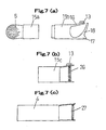
- the engaging portion 10 includes an upper plate 11 and a lower plate 12 that adjoin the rear end of the holding portion 9.
- the upper plate 12 may be made of an elastic plate.
- the upper plate 12 has a bearing portion 12a at its rear end. As shown in Fig. 5 (b), this bearing portion 12a has a projection 12b on the lateral side thereof that will face opposite the lateral side of the longitudinal slit 8 on which the first engaging recess 8a and second engaging recess 8b are located, when the intermediate tubular case 4 is mounted inside the outer tubular case 3.
- the distance as measured vertically between the lower plate 11 and upper plate 12 is becoming larger toward the rear end, starting with the point where those plates are mounted to the holding portion 9.
- the height H1 of the engaging portion 10 that is, the distance as measured vertically between the lower and upper plates 11, 12 on the rear ends thereof is larger than the height or distance H2 as measured vertically between the upper and lower inner walls of the outer tubular case 3 (Fig. 5 (c)).
- the intermediate tubular case 4 that has been constructed as described above may be mounted slidably inside the outer tubular case 3, by inserting the intermediate tubular case 4 into the outer tubular case 3 with the holding portion 9 being placed on the open end side of the outer tubular case 3 and with the distance between the lower and upper plates 11, 12 of the engaging portion 10 being reduced to be smaller than the height H2 between the upper and lower walls of the outer tubular case 3.
- the engaging portion 10 may be brought into engagement with the inner walls of the upper and lower sides of the outer tubular case 3 by the elastic action of the upper plate 12.
- the upper member 16 has its underside 16b on the rear end side that is slanted downwardly from the rear end toward the front end where the mounting portion 15 is located.
- the upper member 16 has an operating member 13 on its upper side.
- the operating member 13 may have a projection 13a on the side thereof that will face opposite the side of the outer tubular case 3 on which the third engaging recess 8c is located, when the inner tubular case 4 is mounted inside the intermediate tubular case 4 that is mounted inside the outer tubular case 3 (Fig. 6 (a)).
- the rear end side of the bearing portion 12a may engage the front side of the rising member 18 on the inner tubular case 6. Then, force may be applied to the rear end side of the bearing portion 12a on the intermediate tubular case 4, which may also urge the intermediate tubular case 4 to begin moving forwardly (in the direction of the arrow 20 in Fig. 1) together with the inner tubular case 6.
- the operating member 13 may be pushed downwardly (in the direction of an arrow 19 in Fig. 1) so that the projection 13a that now engages the fourth engaging recess 8d may be disengaged from the fourth engaging recess 8d.
- force may then be applied to the operating member 13 that causes the inner tubular case 6 to move it backwardly (in the direction of an arrow 24 in Fig. 3).
- the storage case 1 may be restored to its original state (Fig. 1) after it has gone through the sequence as described above.
Landscapes
- Packaging Of Annular Or Rod-Shaped Articles, Wearing Apparel, Cassettes, Or The Like (AREA)
- Purses, Travelling Bags, Baskets, Or Suitcases (AREA)
- Cosmetics (AREA)
Applications Claiming Priority (3)
| Application Number | Priority Date | Filing Date | Title |
|---|---|---|---|
| JP2000102704 | 2000-04-04 | ||
| JP2000102704 | 2000-04-04 | ||
| PCT/JP2001/002926 WO2001074193A1 (fr) | 2000-04-04 | 2001-04-04 | Ensemble de maquillage et etui de stockage de produits cosmetiques |
Publications (3)
| Publication Number | Publication Date |
|---|---|
| EP1269883A1 true EP1269883A1 (fr) | 2003-01-02 |
| EP1269883A4 EP1269883A4 (fr) | 2004-10-20 |
| EP1269883B1 EP1269883B1 (fr) | 2005-08-03 |
Family
ID=18616534
Family Applications (1)
| Application Number | Title | Priority Date | Filing Date |
|---|---|---|---|
| EP01919775A Expired - Lifetime EP1269883B1 (fr) | 2000-04-04 | 2001-04-04 | Ensemble de maquillage et etui de stockage de produits cosmetiques |
Country Status (6)
| Country | Link |
|---|---|
| US (1) | US6886571B2 (fr) |
| EP (1) | EP1269883B1 (fr) |
| JP (1) | JP3806838B2 (fr) |
| AT (1) | ATE300888T1 (fr) |
| DE (1) | DE60112417T2 (fr) |
| WO (1) | WO2001074193A1 (fr) |
Cited By (3)
| Publication number | Priority date | Publication date | Assignee | Title |
|---|---|---|---|---|
| EP2227983A1 (fr) | 2009-03-11 | 2010-09-15 | Tunap Industrie Chemie GmbH & Co. Produktions KG | Outil destiné à l'application d'une substance |
| US8181820B2 (en) | 2008-02-13 | 2012-05-22 | Takeda Brush Inc. | Mechanism for opening and closing an opening portion |
| EP2303057A4 (fr) * | 2008-07-24 | 2014-12-31 | Anisa International Inc | Brosses avec têtes amovibles rétractables |
Families Citing this family (2)
| Publication number | Priority date | Publication date | Assignee | Title |
|---|---|---|---|---|
| KR101173642B1 (ko) * | 2010-05-25 | 2012-08-13 | (주)연우 | 브러쉬의 탈착이 가능한 화장솔이 구비된 색조화장품용기 |
| USD719739S1 (en) * | 2013-03-12 | 2014-12-23 | Carie Brescia, Llc | Retractable cosmetic device |
Family Cites Families (10)
| Publication number | Priority date | Publication date | Assignee | Title |
|---|---|---|---|---|
| US2104364A (en) * | 1931-10-19 | 1938-01-04 | Charles N Coryell | Holder for stick material |
| JPS5660507A (en) * | 1979-10-18 | 1981-05-25 | Haruyo Uno | Holding case for carrying out pushing out of contained article in case and withdrawing operation of case lid plate by one touch |
| JPS5888914U (ja) * | 1981-12-10 | 1983-06-16 | 株式会社吉野工業所 | 棒状化粧品繰出し容器 |
| FR2670656B1 (fr) * | 1990-12-19 | 1993-11-05 | Oreal | Dispositif pour appliquer un produits pateux, notamment un produit cosmetique tel que du rouge a levres, et element tubulaire pour un tel dispositif. |
| JP2905144B2 (ja) * | 1995-09-14 | 1999-06-14 | 有限会社野々川商事 | 棒状化粧料容器 |
| US5860756A (en) * | 1996-11-22 | 1999-01-19 | Rexam Cosmetic Packaging, Inc. | Top-fill/bottom-fill cosmetic carrier for a lipstick container |
| US5860755A (en) * | 1997-03-24 | 1999-01-19 | Bunk; Carole | Lipstick holder with mirror |
| US5979468A (en) * | 1998-03-24 | 1999-11-09 | Blake, Iii; Joseph W | Tube for lipstick and the like |
| JP3675176B2 (ja) * | 1998-06-19 | 2005-07-27 | 株式会社カツシカ | 棒状化粧料繰り出し容器 |
| FR2797754B1 (fr) * | 1999-08-23 | 2001-12-21 | Demellier Joulia | Perfectionnement pour etui tournant |
-
2001
- 2001-04-04 AT AT01919775T patent/ATE300888T1/de not_active IP Right Cessation
- 2001-04-04 JP JP2001571955A patent/JP3806838B2/ja not_active Expired - Lifetime
- 2001-04-04 DE DE60112417T patent/DE60112417T2/de not_active Expired - Lifetime
- 2001-04-04 EP EP01919775A patent/EP1269883B1/fr not_active Expired - Lifetime
- 2001-04-04 WO PCT/JP2001/002926 patent/WO2001074193A1/fr not_active Ceased
- 2001-04-04 US US10/240,847 patent/US6886571B2/en not_active Expired - Lifetime
Cited By (3)
| Publication number | Priority date | Publication date | Assignee | Title |
|---|---|---|---|---|
| US8181820B2 (en) | 2008-02-13 | 2012-05-22 | Takeda Brush Inc. | Mechanism for opening and closing an opening portion |
| EP2303057A4 (fr) * | 2008-07-24 | 2014-12-31 | Anisa International Inc | Brosses avec têtes amovibles rétractables |
| EP2227983A1 (fr) | 2009-03-11 | 2010-09-15 | Tunap Industrie Chemie GmbH & Co. Produktions KG | Outil destiné à l'application d'une substance |
Also Published As
| Publication number | Publication date |
|---|---|
| ATE300888T1 (de) | 2005-08-15 |
| US20030145872A1 (en) | 2003-08-07 |
| EP1269883A4 (fr) | 2004-10-20 |
| DE60112417T2 (de) | 2006-06-01 |
| US6886571B2 (en) | 2005-05-03 |
| EP1269883B1 (fr) | 2005-08-03 |
| DE60112417D1 (de) | 2005-09-08 |
| WO2001074193A1 (fr) | 2001-10-11 |
| JP3806838B2 (ja) | 2006-08-09 |
Similar Documents
| Publication | Publication Date | Title |
|---|---|---|
| US6889696B2 (en) | Cosmetic container with spring-biased mirror | |
| US10911584B2 (en) | Phone case with interchangeable cosmetic accessory attachment system | |
| JPS6214965Y2 (fr) | ||
| KR100466180B1 (ko) | 버튼 개방식 화장품 케이스 | |
| US8991407B2 (en) | Actuatable cosmetic device | |
| EP1269883B1 (fr) | Ensemble de maquillage et etui de stockage de produits cosmetiques | |
| WO2008097002A1 (fr) | Contenant à cosmétiques | |
| JP7493889B2 (ja) | コンパクト容器 | |
| JPH0451701Y2 (fr) | ||
| KR100834449B1 (ko) | 화장용 브러시 | |
| JPH0591Y2 (fr) | ||
| JPH1156453A (ja) | 化粧料容器 | |
| JPH0445614Y2 (fr) | ||
| JP4449438B2 (ja) | 化粧品用コンパクト容器 | |
| JPH038179Y2 (fr) | ||
| JPWO2001074193A1 (ja) | 化粧用具及び化粧品の収納ケース | |
| JPH0516963Y2 (fr) | ||
| JPH0451700Y2 (fr) | ||
| US2725061A (en) | Cosmetic case | |
| JPH0621389Y2 (ja) | 化粧容器セット | |
| JPH0445609Y2 (fr) | ||
| JPH0413104Y2 (fr) | ||
| JPS6214964Y2 (fr) | ||
| JPS6214968Y2 (fr) | ||
| JP2007061393A (ja) | ノック式化粧容器 |
Legal Events
| Date | Code | Title | Description |
|---|---|---|---|
| PUAI | Public reference made under article 153(3) epc to a published international application that has entered the european phase |
Free format text: ORIGINAL CODE: 0009012 |
|
| 17P | Request for examination filed |
Effective date: 20021017 |
|
| AK | Designated contracting states |
Kind code of ref document: A1 Designated state(s): AT BE CH CY DE DK ES FI FR GB GR IE IT LI LU MC NL PT SE TR |
|
| A4 | Supplementary search report drawn up and despatched |
Effective date: 20040902 |
|
| RIC1 | Information provided on ipc code assigned before grant |
Ipc: 7A 45D 40/02 A Ipc: 7A 45D 40/26 B |
|
| GRAP | Despatch of communication of intention to grant a patent |
Free format text: ORIGINAL CODE: EPIDOSNIGR1 |
|
| GRAS | Grant fee paid |
Free format text: ORIGINAL CODE: EPIDOSNIGR3 |
|
| GRAA | (expected) grant |
Free format text: ORIGINAL CODE: 0009210 |
|
| AK | Designated contracting states |
Kind code of ref document: B1 Designated state(s): AT BE CH CY DE DK ES FI FR GB GR IE IT LI LU MC NL PT SE TR |
|
| PG25 | Lapsed in a contracting state [announced via postgrant information from national office to epo] |
Ref country code: CH Free format text: LAPSE BECAUSE OF FAILURE TO SUBMIT A TRANSLATION OF THE DESCRIPTION OR TO PAY THE FEE WITHIN THE PRESCRIBED TIME-LIMIT Effective date: 20050803 Ref country code: AT Free format text: LAPSE BECAUSE OF FAILURE TO SUBMIT A TRANSLATION OF THE DESCRIPTION OR TO PAY THE FEE WITHIN THE PRESCRIBED TIME-LIMIT Effective date: 20050803 Ref country code: NL Free format text: LAPSE BECAUSE OF FAILURE TO SUBMIT A TRANSLATION OF THE DESCRIPTION OR TO PAY THE FEE WITHIN THE PRESCRIBED TIME-LIMIT Effective date: 20050803 Ref country code: LI Free format text: LAPSE BECAUSE OF FAILURE TO SUBMIT A TRANSLATION OF THE DESCRIPTION OR TO PAY THE FEE WITHIN THE PRESCRIBED TIME-LIMIT Effective date: 20050803 Ref country code: FI Free format text: LAPSE BECAUSE OF FAILURE TO SUBMIT A TRANSLATION OF THE DESCRIPTION OR TO PAY THE FEE WITHIN THE PRESCRIBED TIME-LIMIT Effective date: 20050803 Ref country code: BE Free format text: LAPSE BECAUSE OF FAILURE TO SUBMIT A TRANSLATION OF THE DESCRIPTION OR TO PAY THE FEE WITHIN THE PRESCRIBED TIME-LIMIT Effective date: 20050803 Ref country code: TR Free format text: LAPSE BECAUSE OF FAILURE TO SUBMIT A TRANSLATION OF THE DESCRIPTION OR TO PAY THE FEE WITHIN THE PRESCRIBED TIME-LIMIT Effective date: 20050803 |
|
| REG | Reference to a national code |
Ref country code: GB Ref legal event code: FG4D |
|
| REG | Reference to a national code |
Ref country code: CH Ref legal event code: EP |
|
| REG | Reference to a national code |
Ref country code: IE Ref legal event code: FG4D |
|
| REF | Corresponds to: |
Ref document number: 60112417 Country of ref document: DE Date of ref document: 20050908 Kind code of ref document: P |
|
| PG25 | Lapsed in a contracting state [announced via postgrant information from national office to epo] |
Ref country code: SE Free format text: LAPSE BECAUSE OF FAILURE TO SUBMIT A TRANSLATION OF THE DESCRIPTION OR TO PAY THE FEE WITHIN THE PRESCRIBED TIME-LIMIT Effective date: 20051103 Ref country code: DK Free format text: LAPSE BECAUSE OF FAILURE TO SUBMIT A TRANSLATION OF THE DESCRIPTION OR TO PAY THE FEE WITHIN THE PRESCRIBED TIME-LIMIT Effective date: 20051103 Ref country code: GR Free format text: LAPSE BECAUSE OF FAILURE TO SUBMIT A TRANSLATION OF THE DESCRIPTION OR TO PAY THE FEE WITHIN THE PRESCRIBED TIME-LIMIT Effective date: 20051103 |
|
| PG25 | Lapsed in a contracting state [announced via postgrant information from national office to epo] |
Ref country code: ES Free format text: LAPSE BECAUSE OF FAILURE TO SUBMIT A TRANSLATION OF THE DESCRIPTION OR TO PAY THE FEE WITHIN THE PRESCRIBED TIME-LIMIT Effective date: 20051114 |
|
| PG25 | Lapsed in a contracting state [announced via postgrant information from national office to epo] |
Ref country code: PT Free format text: LAPSE BECAUSE OF FAILURE TO SUBMIT A TRANSLATION OF THE DESCRIPTION OR TO PAY THE FEE WITHIN THE PRESCRIBED TIME-LIMIT Effective date: 20060103 |
|
| NLV1 | Nl: lapsed or annulled due to failure to fulfill the requirements of art. 29p and 29m of the patents act | ||
| REG | Reference to a national code |
Ref country code: CH Ref legal event code: PL |
|
| PG25 | Lapsed in a contracting state [announced via postgrant information from national office to epo] |
Ref country code: IE Free format text: LAPSE BECAUSE OF NON-PAYMENT OF DUE FEES Effective date: 20060404 |
|
| ET | Fr: translation filed | ||
| PG25 | Lapsed in a contracting state [announced via postgrant information from national office to epo] |
Ref country code: MC Free format text: LAPSE BECAUSE OF NON-PAYMENT OF DUE FEES Effective date: 20060430 |
|
| PLBE | No opposition filed within time limit |
Free format text: ORIGINAL CODE: 0009261 |
|
| STAA | Information on the status of an ep patent application or granted ep patent |
Free format text: STATUS: NO OPPOSITION FILED WITHIN TIME LIMIT |
|
| 26N | No opposition filed |
Effective date: 20060504 |
|
| REG | Reference to a national code |
Ref country code: IE Ref legal event code: MM4A |
|
| PG25 | Lapsed in a contracting state [announced via postgrant information from national office to epo] |
Ref country code: LU Free format text: LAPSE BECAUSE OF NON-PAYMENT OF DUE FEES Effective date: 20060404 |
|
| PG25 | Lapsed in a contracting state [announced via postgrant information from national office to epo] |
Ref country code: CY Free format text: LAPSE BECAUSE OF FAILURE TO SUBMIT A TRANSLATION OF THE DESCRIPTION OR TO PAY THE FEE WITHIN THE PRESCRIBED TIME-LIMIT Effective date: 20050803 |
|
| REG | Reference to a national code |
Ref country code: FR Ref legal event code: PLFP Year of fee payment: 16 |
|
| PGFP | Annual fee paid to national office [announced via postgrant information from national office to epo] |
Ref country code: FR Payment date: 20160309 Year of fee payment: 16 Ref country code: GB Payment date: 20160330 Year of fee payment: 16 |
|
| PGFP | Annual fee paid to national office [announced via postgrant information from national office to epo] |
Ref country code: DE Payment date: 20160330 Year of fee payment: 16 |
|
| PGFP | Annual fee paid to national office [announced via postgrant information from national office to epo] |
Ref country code: IT Payment date: 20160418 Year of fee payment: 16 |
|
| REG | Reference to a national code |
Ref country code: DE Ref legal event code: R119 Ref document number: 60112417 Country of ref document: DE |
|
| GBPC | Gb: european patent ceased through non-payment of renewal fee |
Effective date: 20170404 |
|
| REG | Reference to a national code |
Ref country code: FR Ref legal event code: ST Effective date: 20171229 |
|
| PG25 | Lapsed in a contracting state [announced via postgrant information from national office to epo] |
Ref country code: FR Free format text: LAPSE BECAUSE OF NON-PAYMENT OF DUE FEES Effective date: 20170502 Ref country code: DE Free format text: LAPSE BECAUSE OF NON-PAYMENT OF DUE FEES Effective date: 20171103 |
|
| PG25 | Lapsed in a contracting state [announced via postgrant information from national office to epo] |
Ref country code: GB Free format text: LAPSE BECAUSE OF NON-PAYMENT OF DUE FEES Effective date: 20170404 |
|
| PG25 | Lapsed in a contracting state [announced via postgrant information from national office to epo] |
Ref country code: IT Free format text: LAPSE BECAUSE OF NON-PAYMENT OF DUE FEES Effective date: 20170404 |