EP1270281A1 - System zur Installation von Reifenketten auf Fahrzeugreifen - Google Patents
System zur Installation von Reifenketten auf Fahrzeugreifen Download PDFInfo
- Publication number
- EP1270281A1 EP1270281A1 EP01305284A EP01305284A EP1270281A1 EP 1270281 A1 EP1270281 A1 EP 1270281A1 EP 01305284 A EP01305284 A EP 01305284A EP 01305284 A EP01305284 A EP 01305284A EP 1270281 A1 EP1270281 A1 EP 1270281A1
- Authority
- EP
- European Patent Office
- Prior art keywords
- tire
- tool
- chain
- tray
- arm
- Prior art date
- Legal status (The legal status is an assumption and is not a legal conclusion. Google has not performed a legal analysis and makes no representation as to the accuracy of the status listed.)
- Withdrawn
Links
- 238000009434 installation Methods 0.000 claims abstract description 30
- 230000013011 mating Effects 0.000 claims abstract description 14
- 230000004044 response Effects 0.000 claims abstract description 3
- 230000007246 mechanism Effects 0.000 claims description 18
- 238000003860 storage Methods 0.000 claims description 9
- 238000005304 joining Methods 0.000 claims description 3
- 210000000078 claw Anatomy 0.000 description 68
- 230000006870 function Effects 0.000 description 9
- 230000002441 reversible effect Effects 0.000 description 9
- 239000000463 material Substances 0.000 description 8
- 239000002184 metal Substances 0.000 description 7
- 230000006835 compression Effects 0.000 description 6
- 238000007906 compression Methods 0.000 description 6
- 238000013461 design Methods 0.000 description 6
- 230000033001 locomotion Effects 0.000 description 6
- 230000004048 modification Effects 0.000 description 6
- 238000012986 modification Methods 0.000 description 6
- 230000011664 signaling Effects 0.000 description 6
- 230000008901 benefit Effects 0.000 description 5
- 230000001965 increasing effect Effects 0.000 description 5
- 238000000034 method Methods 0.000 description 5
- 239000000243 solution Substances 0.000 description 5
- 239000000853 adhesive Substances 0.000 description 4
- 230000001070 adhesive effect Effects 0.000 description 4
- 238000013459 approach Methods 0.000 description 4
- 230000002829 reductive effect Effects 0.000 description 4
- 239000011435 rock Substances 0.000 description 3
- VVQNEPGJFQJSBK-UHFFFAOYSA-N Methyl methacrylate Chemical compound COC(=O)C(C)=C VVQNEPGJFQJSBK-UHFFFAOYSA-N 0.000 description 2
- 229920005372 Plexiglas® Polymers 0.000 description 2
- 229910000831 Steel Inorganic materials 0.000 description 2
- 230000005540 biological transmission Effects 0.000 description 2
- 230000008859 change Effects 0.000 description 2
- 239000004020 conductor Substances 0.000 description 2
- 238000010276 construction Methods 0.000 description 2
- 238000005520 cutting process Methods 0.000 description 2
- 229910003460 diamond Inorganic materials 0.000 description 2
- 239000010432 diamond Substances 0.000 description 2
- 238000004519 manufacturing process Methods 0.000 description 2
- 230000035484 reaction time Effects 0.000 description 2
- 230000000284 resting effect Effects 0.000 description 2
- 239000010959 steel Substances 0.000 description 2
- 210000001364 upper extremity Anatomy 0.000 description 2
- 239000002023 wood Substances 0.000 description 2
- 206010017472 Fumbling Diseases 0.000 description 1
- 241000383563 Heliconia rostrata Species 0.000 description 1
- 239000004677 Nylon Substances 0.000 description 1
- 239000004743 Polypropylene Substances 0.000 description 1
- 241000269400 Sirenidae Species 0.000 description 1
- 239000006096 absorbing agent Substances 0.000 description 1
- 230000009471 action Effects 0.000 description 1
- 230000002411 adverse Effects 0.000 description 1
- 210000003484 anatomy Anatomy 0.000 description 1
- 239000011324 bead Substances 0.000 description 1
- 230000000694 effects Effects 0.000 description 1
- 230000003028 elevating effect Effects 0.000 description 1
- 238000005516 engineering process Methods 0.000 description 1
- 239000005357 flat glass Substances 0.000 description 1
- 239000000446 fuel Substances 0.000 description 1
- 239000011521 glass Substances 0.000 description 1
- 230000006872 improvement Effects 0.000 description 1
- 238000001746 injection moulding Methods 0.000 description 1
- 229920001778 nylon Polymers 0.000 description 1
- 238000010422 painting Methods 0.000 description 1
- 239000004033 plastic Substances 0.000 description 1
- 229920003023 plastic Polymers 0.000 description 1
- 239000002952 polymeric resin Substances 0.000 description 1
- -1 polypropylene Polymers 0.000 description 1
- 229920001155 polypropylene Polymers 0.000 description 1
- 238000002360 preparation method Methods 0.000 description 1
- 230000008569 process Effects 0.000 description 1
- 230000009467 reduction Effects 0.000 description 1
- 230000011514 reflex Effects 0.000 description 1
- 239000012858 resilient material Substances 0.000 description 1
- 229920005989 resin Polymers 0.000 description 1
- 239000011347 resin Substances 0.000 description 1
- 230000000452 restraining effect Effects 0.000 description 1
- 230000000717 retained effect Effects 0.000 description 1
- 230000035939 shock Effects 0.000 description 1
- 125000006850 spacer group Chemical group 0.000 description 1
- 229920003002 synthetic resin Polymers 0.000 description 1
- 238000012360 testing method Methods 0.000 description 1
- 230000000007 visual effect Effects 0.000 description 1
Images


Classifications
-
- B—PERFORMING OPERATIONS; TRANSPORTING
- B25—HAND TOOLS; PORTABLE POWER-DRIVEN TOOLS; MANIPULATORS
- B25B—TOOLS OR BENCH DEVICES NOT OTHERWISE PROVIDED FOR, FOR FASTENING, CONNECTING, DISENGAGING OR HOLDING
- B25B27/00—Hand tools, specially adapted for fitting together or separating parts or objects whether or not involving some deformation, not otherwise provided for
- B25B27/14—Hand tools, specially adapted for fitting together or separating parts or objects whether or not involving some deformation, not otherwise provided for for assembling objects other than by press fit or detaching same
- B25B27/22—Hand tools, specially adapted for fitting together or separating parts or objects whether or not involving some deformation, not otherwise provided for for assembling objects other than by press fit or detaching same positioning sprocket chains, endless tracks, antiskid chains
-
- B—PERFORMING OPERATIONS; TRANSPORTING
- B60—VEHICLES IN GENERAL
- B60C—VEHICLE TYRES; TYRE INFLATION; TYRE CHANGING; CONNECTING VALVES TO INFLATABLE ELASTIC BODIES IN GENERAL; DEVICES OR ARRANGEMENTS RELATED TO TYRES
- B60C27/00—Non-skid devices temporarily attachable to resilient tyres or resiliently-tyred wheels
- B60C27/06—Non-skid devices temporarily attachable to resilient tyres or resiliently-tyred wheels extending over the complete circumference of the tread, e.g. made of chains or cables
- B60C27/10—Non-skid devices temporarily attachable to resilient tyres or resiliently-tyred wheels extending over the complete circumference of the tread, e.g. made of chains or cables having tensioning means
-
- Y—GENERAL TAGGING OF NEW TECHNOLOGICAL DEVELOPMENTS; GENERAL TAGGING OF CROSS-SECTIONAL TECHNOLOGIES SPANNING OVER SEVERAL SECTIONS OF THE IPC; TECHNICAL SUBJECTS COVERED BY FORMER USPC CROSS-REFERENCE ART COLLECTIONS [XRACs] AND DIGESTS
- Y10—TECHNICAL SUBJECTS COVERED BY FORMER USPC
- Y10T—TECHNICAL SUBJECTS COVERED BY FORMER US CLASSIFICATION
- Y10T29/00—Metal working
- Y10T29/49—Method of mechanical manufacture
- Y10T29/49764—Method of mechanical manufacture with testing or indicating
Definitions
- This invention pertains to the field of installing traction-enhancing chains on pneumatic tires of wheeled vehicles, for use on mud, snow, and ice surfaces.
- tire chains have been known for many years. When needed, tire chains provide enhanced traction on mud, snow, and ice surfaces, both for moving and for stopping the vehicle. Also, tire chains are relatively inexpensive and do not affect vehicle ride, handling, fuel economy, or performance when they are not necessary, which is at least 99 percent of the time for 99 percent of the people in the United States.
- the disadvantages of tire chains which, assuming well designed chains are properly selected for a given vehicle, tend to fall into three categories.
- the first category is installation.
- the disadvantages within this category include the considerable time required for installation and the physical difficulty and discomfort involved, often under adverse weather conditions, darkness, or stress. They may further include, depending upon whether a jack is employed, safety considerations or the need to re-adjust the chains after the vehicle has been driven. These disadvantages are described further in the patents identified below and in other patents in U.S. Patent and Trademark Office subclasses 152/213R and 81/15.8.
- the second category of disadvantages is operation of the vehicle after the chains have been installed.
- Some solutions involve ramps having spaced lateral grooves. After the tire chain is laid out with its cross chains lying loosely in the grooves, the vehicle is driven onto the ramp. The grooves allow the cross chains to be adjusted to positions where the necessary degree of tension can be attained before the ends of the chain are connected. See, for example, Garey U.S. patent 2,022,804. Such drive-on ramps are most efficiently used in pairs, one pair for each pair of drive wheels. A problem presented by ramps is the difficulty of stopping the vehicle at the desired position on the ramp. One approach to solving this problem is to provide a stop for the wheel, as disclosed for example in Rhoads et al U.S. patent 2,604,802.
- the present invention is a drive-on system for installing tire chains, including storage and handling, on a pneumatic tire mounted on a vehicle wheel. Its object is to meet the need described above in the manner described above.
- the inventive system utilizes a U-shaped installation tool having arms extending outwardly from opposite ends of a transverse body member or handle. Movable clasp mechanisms at the ends of the arms releasably but securely engage an end element at one end of each side chain.
- the arrangement of the elements of the tool corresponds roughly to the anatomy of a hardshell crab.
- the system also utilizes a tray-like device in which the tire chain and the tool are arranged, and may be stored, in a partially laid-out orientation prior to installation.
- This device which performs the function of the ramps and chain caddy referred to above, will be referred to hereinafter as an "installation tray” or “tray”.
- the installation tray has longitudinal channels and transverse channels for holding laid-out side chains and cross chains, respectively, and a well for holding side chains and cross chains which are not laid out.
- the installation tray also has a compartment adjacent the well for holding the tool and protecting it from damage due to the weight of the vehicle.
- the method of installing the tire chain is as follows.
- the untwisted tire chain is arranged in the tray with the tool connected to it, as described above.
- the vehicle is driven onto the tray and stopped when the vehicle is in a predetermined, optimum position with respect to the tray and chain. Holding the handle, the user draws the tool, with one end of the tire chain trailing it, upward and circumferentially around the tire. With the tool bridging the tread of the tire so that its arms extend along the opposite sidewalls, the tire chain is disposed and tensioned substantially in its correct position on the tire.
- the fastening element at the other, free end of each side chain is then brought up and connected to the mating fastening element.
- connection of the side chain elements on the inner sidewall may be made while the tool is still connected to the fastening element, which enables the arm of the tool on the inner sidewall to be used to guide the free element into contact and connection with the element connected to the tool. In most cases this eliminates the need for the user to see the two elements being connected and the need to hold the two elements with both hands simultaneously, so that the user does not need to lie on the ground. After the tool is disconnected from the chain, the vehicle is driven off the tray.
- the system according to the invention may include additional features.
- the inner arm of the tool may have flanges defining a channel for guiding the free fastening element into proximity and contact with the fastening element held by that arm.
- An inclined ramp-like surface may be disposed in that channel.
- the tray may have slots for locating and restraining the free fastening elements, and stacking lugs and recesses to permit a plurality of trays to be stacked during storage.
- a device may be provided in a recess in the tray to sense the position of the tire and initiate a signal to stop the vehicle. The position of the signal-initiating device relative to the transverse channels in the tray may be adjustable.
- the signal issues when, and only when, the tire is positioned within a predetermined theoretical zone defined by boundaries spaced along the longitudinal axis of the tray, so that the device is able to sense and signal the stopped position of the tire as well as the position of the tire while it is still moving.
- the chain elements held by the arms of the tool may be released therefrom by the action of a readily accessible latch or similar locking device controlled by the user. Force for opening the claws of the tool may be applied to the open latch.
- the handle of the tool may be articulated to permit the claws of the two arms, and the elements of the chain they hold, to be brought close to each other.
- the tool may have features which enable it to be easily adapted and used for tires of different sizes.
- the drawings show the tool and the tray approximately to scale.
- the actual distance between the inner and outer arms of the tool as shown is 8.25 in. (209.55 mm.).
- the actual length of the tray as shown is 33.0 in. (838.2 mm.).
- tire refers to an inflated tire mounted on a rim which is a component of a wheel on a vehicle.
- the tire has a tread which joins 2 sidewalls -- an “inner” sidewall toward the shaft driving the wheel and an opposite, “outer” sidewall.
- inner and outer will be used in a similar manner to refer to an arm of the tool intended to be used adjacent a sidewall.
- the “width” of the tread is the distance between its edges, in the direction parallel to the axis of rotation of the wheel.
- the “maximum width” or “section width” of the tire is its maximum width in a direction parallel to the wheel's axis of rotation and is conventionally the nominal width of the tire.
- the "radius” of the tire is the distance from the axis of rotation to the ground.
- the “footprint” of the tire is the portion of its tread which is in contact with the ground.
- the “bottom dead center” or “BDC” of the tire is the line where its bottom surface intersects a vertical plane including the axis of rotation; the BDC will be approximately at the center of the footprint when the tire is resting on a flat surface.
- tire chain refers to what is installed or is intended to be installed on a single tire.
- Tire chain and “snow chain” are synonyms.
- a tire chain includes side chains and cross chains joined together.
- chain alone will be used to refer to any two or more elements of a tire chain.
- element refers to any element of a side chain or a cross chain, such as a link, a “cross chain hook” connecting a cross chain with a side chain, or a fastening hook at an end of a side chain.
- locking hook will refer to a fastening hook having a camming or locking mechanism.
- open hook will refer to a rigid fastening hook of the type normally used adjacent the inner sidewall of the tire.
- a fastening hook and the link at the opposite end of the side chain to which it is or is intended to be connected will be said to be “mating”.
- fastening element will refer to a hook or a mating link.
- free as used with reference to a chain element, means that the element is not connected to the tool, and thus may refer to an element held by the user or restrained by a holder on the tray.
- side chain circle will refer to a circle drawn through the angles of a polygon formed by a side chain installed on a tire.
- connection angle is the angular position on the tire where, after the tire chain has been properly draped and tensioned, the fastening elements on opposite ends of a side chain are connected; the connection angle is measured from the BDC about the axis of rotation of the wheel.
- the term “interference” will refer to contact of the tool or the hands of the user with a nearby portion of the vehicle (e.g., fenders, mudguards, frame, brakes, steering mechanism, or shock absorbers).
- the term “clearance” will refer to distance between the tire and such a portion of the vehicle which limits positioning or operation of the tool or the hands of the user.
- front and “rear” will be used consistently to refer to the installation tray as though it were a garage facing a street. That is, the tire is intended to enter the front of the tray and stop before it reaches the rear.
- the terms “front” and “rear” will to refer to the installation tool in its orientation when lying in the installation tray, but when the tool is in a different orientation will not correlate to those terms as applied to the tray.
- “front” and “rear” will not necessarily correlate to the direction the vehicle is driven or its orientation.
- in low gear will refer to driving the vehicle with the transmission in drive, low gear, or another forward gear
- in reverse will refer to driving the vehicle with the transmission in reverse.
- mirror image refers to symmetry about a longitudinal, vertical plane.
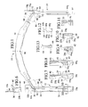
- Installation tool 10 consists of inner arm 12 and outer arm 14 extending from opposite ends of transverse handle or body member 16 .
- inner arm 12 consists of top member 20 and bottom member 40 pivotally connected by rivet 22.
- outer arm 14 consists of top member 60 and bottom member 80 pivotally connected by rivet 62 .
- Top member 20 of inner arm 12 is channel-shaped, with web 20a joining top flange 20b and bottom flange 20c ; see Figs. 7 and 10.
- Spacer 24 , claw holder 26 , and claw 28 are fixed to the front of top member 20 by fasteners or adhesive (not shown); see Figs. 7 and 9.
- Claw 28 has in its flat, horizontal, lower surface a groove 28a which curves in a quarter-circular arc and has a semicircular cross section; see Figs. 2, 3, 7, and 9.
- At the rear of claw 28 is ramp-like member 30 fixed in the channel of top member 20; see Figs. 2, 3, 7, 8, and 15.
- Ramp-like member 30 has flat surface 30a parallel to web 20a and flat surface 30b inclined so that it extends from the level of web 20a to the level of claw 28 .
- a cylindrical cavity in surfaces 30a and 30b creates a concave surface 30c extending from web 20a to claw 28 .
- stop surface 29 At the rear end of top member 20 is downwardly facing stop surface 29 ; see Figs. 2 and 3.
- latch 32 Above stop surface 29 is latch 32, which comprises side leg or panel 32a and top leg or panel 32b; see Figs. 1, 2, 3, 6, and 14.
- Latch 32 is pivotally connected to top flange 20b by rivet 34 .
- latch side panel 32a By contacting latch side panel 32a , rearwardly facing stop surface 36 and the adjacent straight side edge of top flange 20b limit rotation of latch 32 in the direction away from the handle (counterclockwise as shown in Figs. 1 and 6). This is the open or unlatched position of latch 32 , since it allows top member 20 and bottom member 40 to pivot about rivet 22 as shown in Fig. 3.
- Bottom member 40 of inner arm 12 has claw holder 42 and claw 44 fixed to its front end; see Figs. 2, 3, 8, and 9.
- claw 44 has in its flat, horizontal upper surface groove 44a which curves in a quarter-circular arc and has a semicircular cross section; see Figs. 2, 3, 8, 9, and 16.
- bottom member 40 merges at a 120° angle into angular member 46 which is part of the handle.
- Abutment 50 is secured by fasteners or adhesive (not shown) to the rear of bottom member 40 ; see Figs. 2, 3, 6A, and 6B.
- Abutment 50 has rearwardly facing stop surface 51, flange 52, and upwardly facing stop surface 54.
- Grip 56 having side leg or panel 56a and bottom leg or panel 56b is pivotally connected to flange 52 by rivet 58 , which is below and on the same axis as rivet 34 .
- By contacting grip side panel 56a rearwardly facing stop surface 51 and the adjacent straight side edge of abutment flange 52 limit rotation of grip 56 in the direction away from the handle (counterclockwise in Fig. 6A). In this position latch side panel 56a forms an angle of 180° with bottom member 40 .
- the friction between latch top panel 32b and angular member 46 may be increased by providing a thin rubber sleeve (not shown) stretched around the portion of angular member 46 beneath latch 32.
- a pinhead-size, downwardly embossed button detent (not shown) can be provided in top panel 32b to engage angular member 46 in the 120° position.
- the operation of grip 56 is similar to that of latch 32 . Rotation of grip 56 in the direction toward the handle (clockwise in Fig 6A) is limited by angular member 46 , which is contacted by the inside surface of grip side panel 56a . Grip 56 does not perform a latching function.
- top member 20 and bottom member 40 pivot about rivet 22 like pliers, and separates claws 28 , 44 ; see Fig. 3.
- Grip 56 provides an improved bottom surface and increased leverage for applying the squeezing force to cause top member 20 and bottom member 40 to pivot about rivet 22 .
- the user will find it intuitive and easy to simply rotate both latch 32 and grip 56 to the 180° position, and then squeeze their similar, parallel, superimposed surfaces together.
- the pivotal movement of top member 20 with respect to bottom member 40 stops when stop surface 29 contacts stop surface 54 ; see Fig. 3, which shows inner arm 12 in the fully open, releasing configuration.
- Claws 28 , 44 will positively and securely engage and hold an element of an inner side chain, and they will continue to confine the element as long as latch 32 is in the latched position, in such a manner that arm 12 of the tool will remain in this closed, confining configuration and connected to the element during storage, handling, and installation of the tire chain, irrespective of the relative positions of the element and the arm and irrespective of the directions of forces pulling on them.
- Claws 28 , 44 may clasp the element loosely, and are not intended to grip the element by applying a continuous squeezing force.
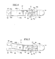
- Top member 60 of outer arm 14 is channel-shaped, with web 60a joining top flange 60b and bottom flange 60c ; see Figs. 1, 4, 5, and 12.
- Claw 64 which has semicircular opening 64a , is fixed to the front of top member 60 by fasteners or adhesive (not shown); see Figs. 1, 4, 5, 12, and 13.
- At the rear end of top member 60 are downwardly facing stop surface 66 , latch 70 (including side panel 70a and top panel 70b ), stop surface 74 , and rivet 72 .
- Bottom member 80 of outer arm 14 terminates at its front end in claw 82 which has semicircular opening 82a, and at its rear end merges into angular member 84; see Figs. 1 and 2. Also at the rear end of bottom member 80 are abutment 87 (including flange 88 and stop surface 89 ), hanger grip 76 (including side panel 76a and bottom panel 76b ), and rivet 78 ; see Figs. 4 and 5. Side panel 76a forms hook 77 .
- Claws 64, 82 will positively and securely engage and hold an element of an outer side chain, and they will continue to confine the element as long as latch 70 is in the latched position, in such a manner that arm 14 will remain in this closed, confining configuration and connected to the element during storage, handling, and installation of the tire chain, irrespective of the relative positions of the element and the arm and irrespective of the directions of forces pulling on them.
- Claws 64, 82 may clasp the element loosely, and are not intended to grip the element by applying a continuous squeezing force.
- FIG. 1 shows outer arm 14 of this embodiment in the fully open, releasing configuration, in which stop surfaces 66 and 89 are in contact with each other.
- Handle 16 is articulated, in that hinge 90 allows claws 28 , 44 of inner arm 12 and claws 64 , 82 of outer arm 14 to be brought together.
- Handle 16 is preferably made from a nonmetallic material, so that it will not rapidly conduct heat away from the user's hand.
- a resilient material such as a section of rubber hose is suitable.
- the hinge may be created by folding the hose and compressing the fold in a vise, and the ends of the hose may be telescoped over a reduced height portion of angular members 46 and 84 and fastened with rivets (not shown). This permits easy rotation of handle 16 at hinge 90 in the plane of tool 10 , and, with considerably more force, limited rotation out of that plane.
- the tool shown in Figs 1-16 is desirably one of a pair used together so that tire chains can be installed on two drive wheels without moving the vehicle more than once.
- the tools may be used either upside down or right side up (as will be described later), but they have been described in the orientation in which the latch is on top. This orientation is preferred when the end elements of the side chains are being connected on the tire, because the latches are more visible and accessible.
- the tool shown in Figs 1-16 is intended for use on the driver side (left) wheel if the tray will be placed ahead of the wheel and the vehicle driven in low gear onto it, or on the passenger side wheel if the tray is being placed behind the wheel and the vehicle driven in reverse onto it.
- the tool will be the mirror image of the tool shown in Figs 1-16.
- the terms "top” and "bottom”, as applied to members 20, 40, 60, 80 , for example, are merely to identify these parts for convenience in describing them.
- the length and spacing of arms 12, 14 will vary with the radius and width of the tire, as will be described later.
- the bottom half of top member 60 of outer arm 14 is eliminated while preserving the hole for rivet 62 by curving the new lower edge in a circular arc around it, and abutment 87 is extended forward to occupy the space thereby created.
- the top and bottom members then separate cleanly along a horizontal axial plane (with the exception of the portions held by the rivet), instead of overlapping like a pair of scissors, and each member has a flange and half of a ramp-like member as well as a claw.
- Inner arm 12 is similarly constructed, with the claws being attached directly to members similar to outer claws 64, 82 .
- an arm may include a tube or casing of rectangular cross-section with a threaded shaft extending longitudinally inside it. At one end the casing forms a seat for an exterior surface of the fastening element, and a hook slides longitudinally within the casing. The outer end of the hook performs the function of claws 28, 44 by engaging an interior surface of the fastening element and pulling it into the seat, while the inner end of the hook is threaded on the shaft.
- the fastening element By rotating a visible knob attached to the shaft outside the other end of the casing, the fastening element may be either pulled into the seat to confine and lock it or ejected from the casing to release it.
- a sliding or pivoting latch extending between the knob and the casing may be employed for locking the clasp for quick release.
- Other examples include a pin-and-yoke, or a cupboard-type latching mechanism.
- the latch or other locking device be visible, readily accessible, and easily operated by the user.
- the arm holding the fastening element be relatively thin in the horizontal direction (no wider than the widest part of the tire chain) and free of abrupt changes in the profile of its surface, in order to minimize the potential for interference.
- tray 110 shown in Figs. 17-21 base or floor 112 with front, entrance lip 113 has, upwardly extending therefrom, rear wall 114 and side walls 116 joined thereto.
- Side walls 116 each have a low portion 116a , a high portion 116b toward the front, another high portion 116c toward the rear, step 116d between portions 116c and 116a, and step 116e between portions 116a and 116b.
- Each side wall 116 also has stacking lugs 116f on its top surface and stacking recesses 116g in its bottom surface.
- the bottom surfaces of base 112 and side walls 116 should have teeth or lugs (not shown) which should be large enough to prevent slipping if the tray is used on ice or snow, yet small enough to support the tray without breaking if the tray is used on pavement.
- front wall or step 118 At the front end of base 112 is front wall or step 118 .
- Two chain element holders 119 are mounted at opposite sides of tray 110 on either base 112 or side wall 116 so that if necessary they may be readily detached, moved forward or rearward, and reattached in the optimum position to accommodate the cross chain length of the particular tire chain being installed.
- front vehicle support 122 Between front wall 118 and rear wall 114 are front vehicle support 122 , center vehicle support 124 , and rear vehicle support 126 .
- Front vehicle support 122 has center portion 122a , left portion 122b , and right portion 122c , which are separated respectively by groove 122d and channel 122e and define signal-initiating device recess 128 .
- Rear vehicle support 126 is relatively close to walls 116 at its maximum width, which is toward the front of the tray, and has rearward-facing concave surfaces 126a .
- center vehicle support 124 is relatively close to walls 116 at its maximum width, which is toward the rear of the tray, and has forward-facing concave surfaces 124a.
- the front and rear walls 118 , 114 and the supports 122, 124, 126 define front transverse channel 130, second transverse channel 132, third transverse channel 134, and rear transverse channel 136 .
- Rear channel 136 is approximately aligned with step 116d in side wall 116 .
- Longitudinal channels 138 extend between supports 122 , 124 , 126 and side walls 116 .
- To the rear of rear support 126 are two interior walls 140 .
- Each interior wall 140 has web 140a between inwardly facing flanges 140b and 140c .
- Chain well 142 is the generally bell-shaped area defined by interior walls 140 , rear support 126 (including concave surfaces 126a ), and side walls 116 , and includes rear transverse channel 136 .
- U-shaped tool compartment 144 To the rear and sides of interior walls 140 is U-shaped tool compartment 144 , which straddles chain well 142 , with a portion of chain well 142 being situated between the legs of the "U". Interior walls 140 are mounted on base 112 so that if necessary they may be readily detached, moved laterally, and reattached in the optimum position to correspond to the width of the particular U-shaped tool 10 being used.
- switch 150 which is supported in signal-initiating device recess 128 by front support center portion 122a , comprises top, rocking element 152 and stationary, bottom element 158 .
- Top element 152 has front bearing surface 152A, rear bearing surface 152B, and terminal 154.
- Stationary bottom element 158 has contact posts 160 , terminal 162 , fastening flange 163 with holes 164 , and guide legs 165 .
- the two elements are made of metal or other electrically conducting material.
- Top element 152 is spaced from bottom element 158 by rigid platform 166 and resilient pad 168 , both of which are non-conducting.
- switch 150 The components of switch 150 are held together by adhesive and a resilient compression band 170 (depicted by phantom lines) surrounding top element 152 and bottom element 158 and passing between guide legs 165.
- Top element 152 is not secured to platform 166 , but is urged against it by band 170 when switch 150 is in a condition of repose.
- band 170 There is a small gap 172 between each post 160 and the bottom of top element 152 .
- top element 152 In the absence of a countervailing downward force on front bearing surface 152A , a downward force on rear bearing surface 152B causes top element 152 to rock about fulcrum 174 at the rear of rigid platform 166 , against the forces applied by compressed pad 168 and tensioned band 170, until gap 172 is closed and posts 160 contact top element 152 , as shown in Fig. 27.
- Switch 150 rests on the bottom portion of resilient compression band 170 and on shims 176 , 178 , and is secured to front support center portion 122a by fasteners (not shown) extending through connecting flange holes 164 .
- Terminal 162 and guide legs 165 embrace center portion 122a on its left and right sides, respectively, so that switch 150 , when it is not so secured, may be slid forward and rearward in recess 128 .
- Switch top element 152 extends out of recess 128 and above the top surface of front support 122 . Thus, switch 150 is situated within, and protected by, front support 122 .
- Two insulated electrical wires are connected to terminals 154 , 162 , extend into channel 122e , and then extend through base 112 to two pairs of terminals 180 at the outside of side walls 116 ; an audio or d.c. power jack may be substituted for each pair of terminals.
- the wires may extend from channel 122e to compartment 184 within front support portion 122c .
- compartment 184 may contain a sending device (not shown) for either emitting a signal similar to those used in remote keyless entry systems for automobiles or emitting an audible sound, preferably a continuous sound.
- the wires within channel 122e are loose and sufficiently slack that switch 150 may be slid forward or rearward to any position along the axis of recess 128 while the wires remain within channel 122e .
- the profile of the top surface of switch 150 may be varied by adapter 181 with projection 182 .
- adapter 181 may be retained on top element 152 by resilient compression band 170 , with projection 182 either toward the front of the tray or toward the rear of the tray, respectively.
- switch 150 is best understood by recognizing that this function could also be performed, at least in theory, by a combination of two separate conventional switches -- a normally closed momentary switch at 152A and a normally open momentary switch at 152B -- wired so that a circuit is closed when, and only when, there is a downward force at 152B but not at 152A .
- Switch 150 is preferred over multiple conventional switches because it is simple and durable and thus well suited for its present application, as will become apparent when use of the invention is described later.
- Figs. 34-39 show an embodiment of the switch system in which front support center portion 122a' abuts front support left and right portions 122b , 122c and has horizontal, rectangular contact bars 190 recessed in its top surface. Wires (not shown) extending through base 112 connect contact bars 190 to terminals 180 or jacks, as shown generally in Fig. 17.
- Switch 150' comprises top, rocking element 152' and stationary bottom element 158' .
- Top element 152' has the general shape of a four-legged footstool, with front legs 191 and rear, contact legs 192 .
- Stationary bottom element 158' has four passages 193 which receive legs 191 , 192.
- Bottom element 158' includes downwardly extending guide legs 165' and fastening flange 163' , which has mounting hole 164' .
- Top element 152' is spaced from bottom element 158' by, and is adhesively bonded or otherwise secured to, rigid platform 166' and resilient pad 168' . Compression springs may be substituted for resilient pad 168' .
- top element 152' is held loosely in place by retaining screw 194 , which is threaded into top element 152' with its head in counterbore 195 in bottom element 158' .
- Top element 152' is made of metal or other electrically conducting material, or at least is electrically conductive between rear legs 192 , while the remainder of switch 150' may be made of either conducting or nonconducting material.
- a fastener (not shown) extending through mounting hole 164' secures switch 150' to front support center portion 122a' .
- Guide legs 165' embrace center portion 122a' to permit switch 150' to be slid forward and rearward along its top surface, within recess 128 , when the fastener is removed from mounting hole 164' .
- Switch top element 152' extends out of recess 128 .
- Legs 191 , 192 are spaced from contact bars 190 by small gaps 172' .
- top element 152' rocks about fulcrum 174 against the force applied by compressed pad 168' , until gaps 172' between rear legs 192 and contact bars 190 are closed and rear legs 192 come into contact with contact bars 190 .
- Leg-receiving passages 193 should have shapes and clearances with legs 191 , 192 which permit free rotation of top element 152' about fulcrum 174 while preventing unnecessary horizontal movement of top element 152' relative to bottom element 158' .
- top rear edge of rigid platform 166' may have, adjacent to and aligned with fulcrum 174 , tongue 196 disposed in a groove in the bottom surface of top element 152' , as shown in Fig. 39.
- fastening flange 163' can be eliminated and bottom element 158' secured to the front support center portion in another manner. (Such a length reduction is advantageous because it allows the front support to be shortened without changing the longitudinal distance over which the switch may be mounted on the center portion.)
- a countersunk hole for a mounting screw may be provided through rigid platform 166' and bottom element 158' , with an access hole through top element 152' .
- the portion of the bottom element engaging the front support center portion may be replaced by a separate plate removably connected by screws to the remaining, upper portion of the bottom element, in such a manner that the plate may be reversed 180° with respect to the remaining portion, thereby enabling the mounting hole to be positioned either at the front or the rear of the bottom element, as desired.
- a separate plate removably connected by screws to the remaining, upper portion of the bottom element, in such a manner that the plate may be reversed 180° with respect to the remaining portion, thereby enabling the mounting hole to be positioned either at the front or the rear of the bottom element, as desired.
- such a plate could be disposed entirely within a longitudinal groove in the top surface of the front support center portion.
- tongue 196 may be replaced by a spindle, for example a dowel pin, which pivotally connects the top element and the bottom element, by extending through holes in upturned flanges at the side edges of the bottom element and corresponding holes in downturned flanges at the side edges of the top element.
- This pivotal connection eliminates the need for front legs 191 , retaining screw 194 , and the positioning function of rear legs 192 .
- the top element may also have downwardly extending walls at its front and rear edges, generally in the planes of the legs shown in Fig. 35, so that the walls form with the side flanges a rectangular skirt which at least partially surrounds the bottom element.
- a third, parallel contact bar may be provided in a center recess in front support center portion 122a' , a corresponding third rear leg provided at the center of top element 152' , and the three contact bars wired so that the electrical path will be closed when the top element makes contact with the center contact bar and either of the side contact bars.
- a resilient pad may be disposed in the center recess beneath the center contact bar, thereby elevating the center contact bar slightly higher than the side contact bars when the center rear leg is not bearing on it.
- switches 150 and 150' are very similar in design and function and respond in the same manner to downward forces on the front and rear bearing surfaces of the top, rocking element.
- Switch 150' is preferred because it eliminates the need for loose wires, is simpler and sturdier, and does not require wires to be connected to the switch.
- the description of the invention hereinafter will refer primarily to switch 150 , but it will be understood that the description also applies to switch 150' unless otherwise stated.
- the tire chain is loaded into tray 110 in its proper orientation and connected to tool 10, as shown in the right hand side of Fig. 17, which depicts ladder-type tire chain 210 having inner side chain 212 , a corresponding outer side chain (not shown in Fig. 17) in left longitudinal channel 138 , twist-link cross chains 216 , fastening hooks comprising inner hook 212H and outer hook 214H , and fastening links comprising inner link 212L and outer link 214L .
- Outer side chain 214 , outer hook 214H and outer link 214L are shown in the upper portions of Figs. 32 and 33.
- this loading is done ahead of time, at a time and place and under conditions chosen by the user for his or her convenience, comfort, and safety.
- the tire chain is preferably laid out on a flat surface with the hooks which connect the cross chains to the side chains facing down. Since twisted chain is a frequent cause of tire chain failure, twists should be removed until each side chain is in a relaxed state. If a side chain is not relaxed at a cross chain hook, it can be untwisted by threading the end of the side chain behind the cross chain. This is repeated until the tire chain is completely relaxed.
- tool 10 is connected to the fastening elements of the side chains at one end of the tire chain.
- inner arm 12 With the tool oriented so that latches 32, 70 are facing down, inner arm 12 will be connected to the side chain which has the open hook, and outer arm 14 will be connected to the side chain which has the locking hook.
- the connection will be made to the appropriate end of the tire chain -- either the end with the hooks or the other end, where the fastening elements are links. If the tool is being connected to the link end, it will be connected to the link which will be eventually connected to the hook when the tire chain is installed, which may not be the endmost link. I recommend pulling each chosen fastening link through a short resilient sleeve, such as narrow bicycle inner tube 310 as shown in Fig.
- the sleeve (not shown in Fig. 17) covers the side chain from the last cross chain to about one-fourth of the chosen link. (This isolates the chosen link from the rest of the links, provides some rigidity to the endmost links, makes the endmost links easier to handle, and reduces hand-to-metal contact. Also, if the chosen link is not the endmost link, it also avoids the disadvantages of cutting the excess side chain link(s) or merely wiring or tying them to the side chain.
- Sleeve 310 can be made more rigid, as for example by making it from, or using it inside of another sleeve made of, a material having a greater wall thickness, such as rubber hose or plastic tubing, thereby making the end of the side chain easier to handle, which is an advantage not only in the fastening of the chain elements but also in the unfastening of them when the tire chains are removed. Also, a similar sleeve or sleeves may be used as well on the end of the side chain with the mating fastening hook, and the sleeve(s) may be extended past the side chain(s) to provide rigidity over a greater length of side chain, as for example by lengthwise slitting and circumferential taping of the sleeve.)
- claws 28, 44 are separated to the open position, the inner fastening element (link or open hook) is placed in groove 44a, the claws are closed together by squeezing top claw holder 26 and bottom claw holder 42, and latch 32 is moved to the latched position; see the lower portions of Fig. 32 or 33, disregarding the phantom lines for the moment.
- link or open hook the inner fastening element
- fastening element and claws 28, 44 should be noted, since it provides advantages when the tire chain is stored, handled, and installed.
- a small portion of the fastening element (a quarter-circular arc at one end) is securely but releasably confined within the passage formed by grooves 28a, 44a; the remainder of the fastening element is exposed.
- the claws occupy very little of the interior space within the fastening element (approximately 2 percent).
- the fastening element cannot rotate about its longitudinal axis, and cannot move longitudinally or transversely with respect to tool arm 20.
- open hook 212H and the passage size illustrated in Fig. 33 both are approximately 0.250 in. (6.35 mm.) diameter
- the length of the straight portion at hook end 212He (approximately 0.750 in. (19.05 mm.)) prevent such rotation, but it is desirable for the tool to be able to accommodate open hooks of different sizes and configurations.
- open hook thicknesses range from about 0.250 in. (6.35 mm.) for standard tire chains and about 0.165 in. (4.191 mm.) for low clearance, Class "S" tire chains. Claws 28, 44 shown in the lower portions of Figs.
- a second such modification would be to add to each claw a small pin or screw that obstructs a portion of the passage when the tool is being used with a hook whose metal diameter is substantially less than the diameter of the passage, for example two opposed, conically tipped set screws lying on a vertical axis at the edge of the passage nearest the center of each claw (i.e., at the midpoint of the longer quarter-circular broken line at the lower left corner of Fig. 1).
- a third such modification would be to change the hook itself by extending the straight portion at the end of the hook so that it cannot pass through the passage.
- outer arm 14 is connected to the outer fastening element (link or locking hook) in a manner similar to inner arm 12 , as shown in the upper portion of Fig. 32 or 33, and latch 70 is latched.
- Hanger 76 is pivoted against handle 16 so that it is directly beneath latch 70 .
- Claws 64, 82 shown in the upper portions of Figs. 32 and 33 have been found satisfactory for typical locking hooks, such as locking hook 214H, but as with claws 28, 44 it may be necessary to make modifications to enable them to accommodate hooks of different sizes and configurations. Possible modifications include increasing the height and/or length of the claws, and to either change the configuration of the circular passage or add additional openings near the circular passage to create one or more additional passages of different configuration.
- tool 10 is connected to the tire chain, a minor portion (approximately one-third) of the tire chain at the end remote from the handle is picked up and moved laterally onto tray 110 , with the hooks of the cross chains still facing down and with the cross chain farthest from tool 10 fitting into front transverse channel 130 .
- the remaining, major portion (approximately two-thirds) of the tire chain is raised by tool 10 to a vertical position and then lowered and laid down in a Z-folded fashion to fill chain well 142 , with the cross chains remaining more or less perpendicular to the longitudinal axis of tray 110 and close together, and the side chains piling up to fill in the cavities.
- Tool 10 is placed in tool compartment 144.
- the chain in chain well 142 is then spread so that it is not piled above rear wall 114 and side walls 116.
- the links next to the fastening element at the other end of the tire chain are placed in slots 120 , which fixes that end of the tire chain with the fastening elements exposed.
- the tire chain is now laid out in the tray as shown in the right side of Fig. 17, with the walls of the tray and the supports confining the tool and the various elements of the tire chain so that they remain oriented and cannot become commingled.
- Tool inner arm 12 is connected to inner fastening link 212L and, as shown in Figs. 32 and 33, tool outer arm 14 is connected to outer fastening link 214L .
- Inner fastening hook 212H (shown in Figs. 32 and 33) and outer fastening hook 214H are held just forward of slots 120 .
- the tool will be connected to the fastening hooks of the second tire chain, and the fastening links of the second tire chain will be just in front of slots 120 (not shown).
- the second tire chain is a mirror image of the first (i.e., the first tire chain and the second tire chain are identical, except that the open hook and the locking hook are reversed)
- the tool will be connected to the same kind of fastening elements (either links or hooks) on both tire chains. In this case it probably will be preferable to connect the tool to the hooks (as shown in Fig.
- connection of the fastening hooks to tool 10 keeps the hooks from snagging on another portion of the tire chain during storage, handling, and installation.
- a switch 150 is required for only one tray, which should be the tray on the driver's side of the vehicle.
- the loaded trays are stored by stacking one on the other, with stacking lugs 116f of the lower tray fitting into stacking recesses 116g of the upper tray. They can be stored indoors or in the vehicle ready for use, preferably with other loaded trays, so that even if a set of tire chains which have been installed are removed because of bare pavement, a fresh set of tire chains can be installed as necessary without having to re-load the removed set of tire chains back into their trays.
- front lip 113 of the front end of each of the loaded trays is butted against a drive wheel tire with the longitudinal axis of each tray in the center of the path of the tire.
- the trays may be placed ahead of the tire and the vehicle driven in low gear onto them, in which case the connections between the ends of the side chain will occur behind the tire (i.e., toward the vehicle's backup lights).
- the trays may be placed behind the tire and the vehicle driven in reverse onto them, in which case those connections will occur ahead of the tire (i.e., toward the vehicle's headlights).
- the user will determine which, based on the design of the particular vehicle and possibly other circumstances, as will be described later in the discussion of setup.
- the vehicle is driven slowly in a straight line onto the tray so that the tire climbs over front wall 118 and onto front support 122.
- the tire then passes onto switch 150, which has been secured to support 122 as previously described in the description of the tray, in a specific forward-and-rearward position predetermined in a manner which will be described later in the discussion of setup.
- the tire 302 is exerting a downward force on both front bearing surface 152A and rear bearing surface 152B of top element 152, so that switch 150, which is within the footprint of the tire, remains open.
- the tire continues over switch 150 in the direction indicated by arrow 184 until the trailing edge of the tire lifts off bearing surface 152A, while still exerting a downward force on bearing surface 152B.
- top element 152 rock about fulcrum 174, so that the switch closes, as shown in Fig. 27.
- the contact surface of top element 152 which was adjacent gap 172 is driven by the weight of the vehicle downward against the contact surfaces of posts 160 of bottom element 158, which tends to breach any oxide layer on the contact surfaces and otherwise creates a firm electrical contact.
- the closing of the switch initiates a visual or audible signal to the driver, signalling the driver to apply the brakes and stop the vehicle. If, after the vehicle is stopped, the signal continues, the driver knows that the tire is in the correct position.
- the ability to sense and signal whether or not the tire is within a small zone on the tray is superior to the ability to merely sense and signal whether or not the tire has passed a point on the tray.
- the former provides two limits. The latter provides only one, and hence cannot eliminate variables such as vehicle speed, throttle pressure, throttle reaction time, braking reaction time, variations in these from driver to driver, and variations produced by external conditions such as grade, road surface, and the presence of snow or ice.
- Adapter 181 may be employed as desired to shorten or lengthen this sensing and signalling zone by changing the effective profile of the top surface of switch 150.
- adapter 181 In the position shown in Fig. 29, with the maximum height of the switch surface toward the front of the tray, adapter 181 shortens the zone. (It can be seen from Fig. 28 that if a projection were to extend upward from surface 152A for a distance greater than the distance to the tire, the tire could not contact surface 152B and the zone would be in effect reduced to zero.)
- adapter 181 lengthens the zone by causing switch 150 to close sooner.
- the signalling zone may be shortened or lengthened by varying the distance by which the top surface of top element 152 projects above the plane of the top surface of front support left and right portions 122b, 122c, as for example by shims between center section 122a and base 112.
- the user may simply rely upon instructions or signals from a spotter observing the tire and tray from outside the vehicle, or may use a trial-and-error method in which the user stops and leaves the vehicle to observe.
- interior walls 140 and exterior walls 114, 116 will protect tool 10 from damage due to the weight of the vehicle bearing on it.
- interior walls 140 keep chain in well 142 from spilling or being displaced onto the top of tool 10 and then damaging the tool when the tire is driven onto this overlying chain.
- the user grasps the handle of the tool and draws it, with the chain to which it is connected trailing it, upward and circumferentially around the tire, so that it slides over the surface of the tire and is guided along it in a circular arc about the axis of rotation of the wheel.
- the user may initially keep the tire chain on the top of the tread.
- the cross chains will be guided along the tread and sidewalls, and the side chains will be guided along the sidewalls.
- Fig. 31 shows tire 302 mounted on rim 304 driven by axle 306, and tool 10 connected to the fastening elements of the side chains.
- Tire 302 has tread 302a, inner sidewall 302b, and outer sidewall 302c.
- Handle 16 is now bridging the tread of tire 302, with the arms extending along opposite sidewalls. Claws 28, 44 of inner arm 12 are connected to inner fastening link 212L of inner side chain 212.
- Resilient sleeve 310 isolates fastening link 212L, as previously mentioned with respect to loading the tray.
- the user (not shown) is standing on the side of the wheel away from the viewer, facing the viewer and the outer sidewall and holding handle 16 with his or her right hand much the same way as one would hold the body of a hardshell crab to avoid being pinched by the crab's claws.
- hanger 76 may be pivoted away from handle 16 and the free outer fastening element hung on hook 77. This reduces the weight of the free chain which the user must soon support when picking up and handling the inner fastening element and keeps the tire chain from inadvertently being allowed to fall behind the wheel.
- Figs. 32 and 33 show what happens next for both cases -- when tool 10 is connected to links and when it is connected to hooks, respectively.
- the user picks up the free inner fastening element (or the tube surrounding the side chain links between it and the nearest cross chain) from the tray and brings it up into the channel formed by flanges 20b, 20c and web 20a of member 20 of inner arm 12.
- the user slides the free fastening element (212L or 212H) toward the claws.
- the fastening element contacts concave inclined surface 30c , the user, feeling that it is close to the claws, moves it along that surface, whose concavity centers the fastening element as it approaches the claws.
- the fastening element leaves surface 30c and moves the remaining distance to the mating fastening element connected to the claws.
- mating hook 212H passes above link 212L (out of the longitudinal axis of arm 12 ), remaining in contact with link 212L, until the end 212He of hook 212H is within the interior of link 212L. Then hook 212H is withdrawn into its position of final engagement with link 212L, which is conventional (not shown).
- the necessary passage of hook 212H over link 212L with adequate clearance is possible because of the relatively small portions of the link and its interior space which are obstructed by the claws, as previously described with respect to loading the tray.
- the other tire chain is installed on the other driving wheel in a similar manner, after which the tools and empty trays are stored and the vehicle is driven off the tray in the opposite direction, so that it goes back over the front of the tray. If the vehicle is inadvertently driven in the wrong direction and passes over rear wall 114 of tray 110, the tray will not be damaged.
- the tire chains can be installed in most cases without the need for the user to see the inner fastening elements being connected or to hold them with both hands simultaneously, which often has required the user to lie on the ground when installing tire chains in the conventional manner.
- the user knows that the tool has prevented the side chain from twisting during storage, handling, or installation, since one end of the tire chain is still connected to the tool, the other end is still held by the chain element holder, and the tire chain the tool cannot be rotated about the axis of the handle, as could be possible with a more flexible or differently configured tool.
- the tool positively fixes the location of the connected fastening element.
- the tool guides the free fastening element into contact and engagement with the connected fastening element.
- the tool prevents the connected fastening element from moving or rotating away from the free fastening element in response to pressure from it.
- the tool prevents the hook from snagging on another portion of the tire chain.
- the invention eliminates the need for the user to have both hands holding the mating inner fastening elements at the inner sidewall, which, like the need to see the fastening links, could also require him or her to lie on the ground, since balancing on one's feet may be difficult under these circumstances. Instead, the user is able to see the latches, which are remote from the fastening elements being connected, and to apply tension to the inner side chain through the tool, which one hand (the hand lest able to reach the inner sidewall of the tire) is holding by the handle.
- connection angle will vary with the design of the particular vehicle. On some vehicles, particularly trucks, buses, graders, and other heavy equipment, clearance may not be a factor, either because the tires are sufficiently spaced from the vehicle's fenders or because there are no fenders at all. For these vehicles the optimum connection angle may be within the range of approximately 45° to 170° from the bottom of the tire, in the direction away from chain well 142. An angle less than approximately 45° will place the fastening elements so close to the ground that arms 12, 14 of tool 10 cannot come close enough to the tangent of the side chain circle to enable inner arm 12 to properly guide the free fastening element to the mating element connected to the tool. An angle greater than 170° will prevent the chain from being properly draped on the tire.
- connection angle will be limited to the lower angles of that range which place the elements being connected, or at least the handle of the tool and the knuckles of the user's hand gripping it, below the body of the vehicle.
- the connection should be made at about 90° or, if there is insufficient clearance at 90°, at the lesser connection angle which allows sufficient clearance for the connection to be made.
- the user will have decided in advance whether to drive the vehicle onto the tray in low gear or reverse, based on the design of the body of the vehicle.
- the presence of mud guards close to the tire may militate for reverse, for example.
- the vehicle is a passenger car or light truck with rear wheel drive, it usually will be preferable to drive it in low gear onto the tray.
- front wheel drive passenger cars the preferred practice varies greatly with the design of the front fenders, although these vehicles tend to be more forgiving than rear wheel drive vehicles, since the body is spaced sufficiently far from the front wheel to allow the wheel to turn fully to the right and left.
- the length of the sensing and signalling zone and the location of switch 150 should be predetermined for particular tires and tire chains at or before the first time the tire chains are loaded into the tray in anticipation of actual use.
- the length of the sensing and signalling zone may be determined by trial and error without having the tire chains in the tray.
- adapter 181 should not be used, and the top surface of top element 152 should be coplanar with the top surface of front support left and right portions 122b, 122c, so that top element 152 will be contacted by the part of the tire tread bulging down between front support left and right portions 122b, 122c.
- the vehicle is then driven slowly onto the tray until switch 150 closes and then re-opens.
- the duration and length of the closing should be definite and discernable, but as brief as possible and repeatable. If the zone is too long, a shim under center section 122a should be removed or adapter 181 should be installed as shown in Fig. 29. If the zone is too short or there is no signal, a shim should be added or adapter 181 should be installed as shown in Fig. 30.
- switch 150 it is detached from support 122 and reattached as far as possible to the rear of support 122.
- the tray is loaded into the tray as shown in Fig. 17, with the endmost cross chain in front transverse channel 130.
- the vehicle is then driven onto the tray and stopped when switch 150 is in the closed position shown in Fig. 27. If the resulting connection angle is too great, the vehicle should be driven toward the front end of the tray to produce a lesser angle. If, on the other hand, the resulting connection angle is too small, then the vehicle should be driven off the tray, the tire chain in the tray shifted so that the two endmost cross chains are in front transverse channel 130, and switch 150 moved to a more forward location on support 122.
- the length of support 122 is selected so that the range of the possible positioning of switch 150 is roughly equal to the center-to-center spacing of the cross chains, which in the case of the ladder-type chains shown is 5.0 or 5.25 in. (127 or 133.35 mm.)) If necessary, more than two cross chains may be placed in channel 130.
- the user should by trial and error position the tire and actually drape the tire chains around the tire and tension them to achieve and confirm both the optimum connection angle and the optimum chain length (generally, as short as possible) and to put sleeves 310 on the ends of the side chains on which the fastening element is a link.
- the optimum chain length should be determined for, and sleeves applied to, the other tire chain of the set and its tire. As mentioned earlier, only the tray on the driver's side will employ a switch.
- the user needs to take into account the distance, on the tire chain of the pair which will be in the tray without the switch, between the fastening element at the free end of the side chain (i.e., the end in chain element holder 119 ) and the closest cross chain. If that distance is appreciably longer than the corresponding distance on the tire chain in the tray with the switch, the optimum connection angle to be achieved by the switch should be reduced accordingly.
- switch 150 should be moved and secured to support 122 so that it contacts the rear profile of the tire, as shown in Fig. 31.
- the cross chain(s) in transverse channel 130 should be placed over the front of support 122; otherwise, a relatively short cross chain may catch on the front surface of support 122 if the tire chain is being slid toward the rear of the tray.
- the chains and tool may be painted or otherwise marked so that the fastening elements and the corresponding tool arm can be quickly identified. I recommend painting the inner fastening elements and tool arms one color and the outer fastening elements and tool arms a contrasting color. Also, to identify and distinguish the side chains, the outer side chain links to which the tensioners will be connected can be painted the outer color.
- An effective and convenient signal is a light on the vehicle's instrument panel which is illuminated when the tire is in the zone. Such a light would be actuated by a remote keyless entry-type device and battery in compartment 184, in accordance with known technology.
- an electronic device for emitting an audible sound could be placed in compartment 184 with a battery, preferably with a manual on-off switch in the circuit with switch 150 so that the user could turn off the sound as soon as he leaves the stopped vehicle, thereby sparing himself and others the annoyance of having to listen to it for an extended period.
- a chip in the device which automatically turns off the sound at a fixed interval after it begins would serve the same purpose. Suitable piezo and electromagnetic buzzers and sirens are available from Radio Shack, U.S. Electronics, Inc., St. Louis, MO, and, Kayer Industrial Co., Ltd., Hong Kong.
- An inexpensive third alternative is a light wired to one pair of terminals 180 and placed in the driver's view.
- An example is an ordinary flashlight wired with terminals 180 in parallel with the flashlight's own on-off switch.
- a jack with an integral normally closed switch can be substituted for terminals 180, in series with the on-off switch.
- the flashlight can be attached to the driver's front fender with a magnet or, if the tray is at a rear wheel, to the side of vehicle to the rear of the driver and directed to the outside rear view mirror.
- Such a flashlight can carry its own battery. If the flashlight has plug-in jacks for the wires, it may be used as a normal flashlight when it is not being used with the tray.
- flashlights with suitable jacks are the continuity tester flashlights available from Bright Star Industries, Wilkes-Barre, PA.
- the light can be attached to the windshield or other window glass by a suction cup.
- Clear suction cups of the type available from Presto Galaxy Suction Cups, Inc, Greenpoint, NY allow an embedded or adjacent L.E.D. or small incandescent lamp to be seen through the suction cup and the glass.
- the length of arms 12, 14 should be sufficient to allow the claws to place the fastening links at the widest part of the tire, while the arms are held more or less in alignment with the end links of the side chain and tangent to the side chain circle. This enables the user to pull on handle 16 to properly tension the side chains and cross chains, as mentioned above.
- the length of arms 12, 14 should be no longer than necessary, to minimize the possibility of interference between the tool and the vehicle and to keep the length of tray 110 to a minimum.
- an arm length in the range of from 4 to 6 in. (101.6 to 152.4 mm.) is suitable for typical passenger car tires ranging from 13 to 16 in. (330.2 to 406.4 mm.) bead diameter and from 6.75 to 9.25 in. (171.45 to 234.95 mm.) maximum width.
- An arm length of 4.75 in. (120.65 mm.) is a good compromise which will enable a single tool to work with most passenger car tires.
- the spacing between arms 12, 14 should be greater than the maximum width of the tire but not so great as to cause interference with the vehicle. The optimum is approximately the maximum width of the tire plus 1.0 in. (25.4 mm.). The spacing of arms 12, 14 can be easily changed by cutting or replacing the resilient member of handle 16.
- This angle should be from 45° to 90°, and, to conform to the profile of most passenger car tires, is preferably about 60°.
- the minimum interior width of the tray i.e., the distance between the interior surfaces of side walls 116, which is the width of tool compartment 144 ) should be sufficient to allow the tool to fit between them, and thus should be in the range of about 8.0 to 11.0 in. (203.2 to 279.4 mm.) for the passenger car tire sizes mentioned above. These widths are sufficient to prevent the tire from trapping a side chain in a longitudinal channel 138, unless the path of the tire is badly misaligned with the tray. Excess tray width has no disadvantage other than cumbersomeness.
- the distance between transverse channels 130, 132, 134, 136 should correspond to the distance between the cross chains as measured along a side chain (conventionally 5.0 or 5.25 in.
- the length of tool compartment 144 should be the tool arm length plus about 1.0 in. (25.4 mm.) to accommodate handle 16 and angular member 84. Thus, the tool compartment length should be in the range of about 5 to 7 in. (127 to 177.8 mm.) for typical passenger car tires.
- the height of tool compartment 144 measured to from the top of walls 116, 140 to the floor of the compartment at base 112, should be at least the height of tool 10, which is 1.0 in. (25.4 mm.) as shown in the drawings.
- the depth of tool compartment 144 should be in the range of about 0.75 to 1.5 in. (19.05 to 38.1 mm.).
- tool 10 is made from 0.125 x 1.0 in. (3.175 x 25.4 mm.) steel bar, .0625 x 1.0 in. (1.5875 x 25.4 mm.) square steel tube, 0.75 in. (19.05 mm.) outside diameter radiator hose, and 0.50 in. (12.7 mm.) plexiglass sheet for rigid platform 166', while tray 110 is made from wood of 0.75 and 1.5 in. (19.05 and 38.1 mm.) thicknesses.
- a hinged wood handle is used.
- Switch 150 is made from square metal angle, plexiglass sheet for rigid platform 166, shoe insole material for resilient pad 168, all 0.125 in.
- tool 10 could be made by injection molding a suitable polymeric resin, such as polypropylene or nylon, which may be fiber-reinforced.
- the tray could also be molded from a similar such resin. It will be further understood that the designs of the tool and tray can and would be expected to be changed to accommodate, and take advantage of, the different materials, while continuing to use the fundamental principles and relationships described herein.
- the outer claws can be similar to the inner claws, but with grooves in the claws shaped to receive either a chain link or the curved, J-shaped end portion of the locking hook, for example flat locking hook 214H; this embodiment facilitates the connection of the fastening elements when the fastening link is being held by the outer claws.
- the handle can be offset from the plane of the arms, so that it would appear to be all or part of an inverted "U" in a complete front view of the tool shown in Fig. 1.
- handle 16 telescopes in two places -- between hinge 90 and angular member 46 and between hinge 90 and angular member 84 -- so that the distance between arms 12, 14 may be reduced while tool 10 is stored in tray 110. This eliminates the width of tool 10 as the factor determining the width of tray 110 , as previously described in the discussion of dimensions, in which case the width of tray 110 should be at least the maximum width of the tire.
- the vehicle supports are shaped to correspond to the spaces between cross chains in a Z or diamond configuration, rather than a ladder configuration, so that the transverse channels are diagonal with respect to the longitudinal channels rather than perpendicular.
- the cross chains may also have other configurations and may include elements which are not chain links, as shown for example in Zeiser et al U.S. patent 4,889,172 and Baldry U.S. patent 4,357,975.
Landscapes
- Engineering & Computer Science (AREA)
- Mechanical Engineering (AREA)
- Vehicle Step Arrangements And Article Storage (AREA)
- Hand Tools For Fitting Together And Separating, Or Other Hand Tools (AREA)
- Tires In General (AREA)
Priority Applications (3)
| Application Number | Priority Date | Filing Date | Title |
|---|---|---|---|
| US09/879,629 US20010027596A1 (en) | 1997-03-04 | 2001-06-12 | System for installing chains on vehicle tires |
| CA2351102A CA2351102C (en) | 2001-06-12 | 2001-06-18 | System for installing chains on vehicle tires |
| EP01305284A EP1270281A1 (de) | 2001-06-12 | 2001-06-18 | System zur Installation von Reifenketten auf Fahrzeugreifen |
Applications Claiming Priority (3)
| Application Number | Priority Date | Filing Date | Title |
|---|---|---|---|
| US09/879,629 US20010027596A1 (en) | 1997-03-04 | 2001-06-12 | System for installing chains on vehicle tires |
| CA2351102A CA2351102C (en) | 2001-06-12 | 2001-06-18 | System for installing chains on vehicle tires |
| EP01305284A EP1270281A1 (de) | 2001-06-12 | 2001-06-18 | System zur Installation von Reifenketten auf Fahrzeugreifen |
Publications (1)
| Publication Number | Publication Date |
|---|---|
| EP1270281A1 true EP1270281A1 (de) | 2003-01-02 |
Family
ID=27171568
Family Applications (1)
| Application Number | Title | Priority Date | Filing Date |
|---|---|---|---|
| EP01305284A Withdrawn EP1270281A1 (de) | 1997-03-04 | 2001-06-18 | System zur Installation von Reifenketten auf Fahrzeugreifen |
Country Status (3)
| Country | Link |
|---|---|
| US (1) | US20010027596A1 (de) |
| EP (1) | EP1270281A1 (de) |
| CA (1) | CA2351102C (de) |
Families Citing this family (5)
| Publication number | Priority date | Publication date | Assignee | Title |
|---|---|---|---|---|
| KR100507138B1 (ko) | 2001-12-26 | 2005-08-09 | 현대자동차주식회사 | 차량의 스노우체인 구동제어 장치 |
| US9278782B2 (en) * | 2010-08-20 | 2016-03-08 | Becklin Holdings, Inc. | Handle assembly for a container |
| US9834048B1 (en) * | 2014-08-25 | 2017-12-05 | Richard D Price | Chain installation system for semi-trucks and trailers |
| US11497320B2 (en) | 2020-08-01 | 2022-11-15 | Layla Sleep, Inc. | Dual firmness spring mattress |
| CN116968481A (zh) * | 2022-04-06 | 2023-10-31 | 唐榕羚 | 一种橡胶复合材料充气轮胎 |
Citations (10)
| Publication number | Priority date | Publication date | Assignee | Title |
|---|---|---|---|---|
| DE155387C (de) | ||||
| US2022804A (en) | 1934-02-02 | 1935-12-03 | Garey John | Device for applying tire chains |
| US2175395A (en) * | 1937-06-09 | 1939-10-10 | Frank B Hewel | Device for attaching tire chains |
| US2604802A (en) | 1951-02-17 | 1952-07-29 | John H Rhoads | Adjustable ramp for tire chain application |
| US2865422A (en) * | 1956-02-15 | 1958-12-23 | Royer Ella Dale | Vehicle tire anti-skid chain and applying means |
| US4194724A (en) | 1979-03-19 | 1980-03-25 | Gregory Masegian | Chainmate |
| US4210036A (en) | 1977-10-15 | 1980-07-01 | Nakata Giken Co., Ltd. | Tire-chain handling tools |
| US4357975A (en) | 1980-10-02 | 1982-11-09 | Dominion Chain Inc. | Anti-skid chain |
| US4703675A (en) | 1986-08-07 | 1987-11-03 | Dalaba O Gene | Adjustable tire chain installer |
| US4889172A (en) | 1987-07-08 | 1989-12-26 | Rud-Kettenfabrik Rieger & Dietz Gmbh, U. Co. | Anti-skid device for vehicle wheels |
-
2001
- 2001-06-12 US US09/879,629 patent/US20010027596A1/en not_active Abandoned
- 2001-06-18 CA CA2351102A patent/CA2351102C/en not_active Expired - Fee Related
- 2001-06-18 EP EP01305284A patent/EP1270281A1/de not_active Withdrawn
Patent Citations (10)
| Publication number | Priority date | Publication date | Assignee | Title |
|---|---|---|---|---|
| DE155387C (de) | ||||
| US2022804A (en) | 1934-02-02 | 1935-12-03 | Garey John | Device for applying tire chains |
| US2175395A (en) * | 1937-06-09 | 1939-10-10 | Frank B Hewel | Device for attaching tire chains |
| US2604802A (en) | 1951-02-17 | 1952-07-29 | John H Rhoads | Adjustable ramp for tire chain application |
| US2865422A (en) * | 1956-02-15 | 1958-12-23 | Royer Ella Dale | Vehicle tire anti-skid chain and applying means |
| US4210036A (en) | 1977-10-15 | 1980-07-01 | Nakata Giken Co., Ltd. | Tire-chain handling tools |
| US4194724A (en) | 1979-03-19 | 1980-03-25 | Gregory Masegian | Chainmate |
| US4357975A (en) | 1980-10-02 | 1982-11-09 | Dominion Chain Inc. | Anti-skid chain |
| US4703675A (en) | 1986-08-07 | 1987-11-03 | Dalaba O Gene | Adjustable tire chain installer |
| US4889172A (en) | 1987-07-08 | 1989-12-26 | Rud-Kettenfabrik Rieger & Dietz Gmbh, U. Co. | Anti-skid device for vehicle wheels |
Also Published As
| Publication number | Publication date |
|---|---|
| CA2351102C (en) | 2010-04-06 |
| US20010027596A1 (en) | 2001-10-11 |
| CA2351102A1 (en) | 2002-12-18 |
Similar Documents
| Publication | Publication Date | Title |
|---|---|---|
| US6681657B2 (en) | System for installing chains on vehicle tires | |
| US6053336A (en) | Wheel retention device with externally rotatable multi-faceted retention ring | |
| CA2100004C (en) | User friendly wheel chock | |
| US7448596B1 (en) | Cable tightening device having anti-theft function | |
| US6308383B1 (en) | Apparatus and system for securing cargo | |
| CN1309586C (zh) | 用于汽车轮的防滑装置 | |
| US7708175B2 (en) | Vehicular tool restraint apparatus | |
| CA2351102C (en) | System for installing chains on vehicle tires | |
| US4360052A (en) | Portable tire tool | |
| US6263554B1 (en) | System for installing chains on vehicle tires | |
| US7363952B2 (en) | Non-return block for snow chains having inserts to protect wheel | |
| US7055567B1 (en) | Tire traction apparatus | |
| KR101289292B1 (ko) | 자동차용 스노우 체인 | |
| US20030041702A1 (en) | Automobile brake cable positioning pliers | |
| EP1435304B1 (de) | Verbindungs- und Spanneinrichtung für Schneeketten | |
| CA1060328A (en) | Anti-skid attachment for vehicle tires | |
| US20210253035A1 (en) | Bicycle frame cradle with fold-in anti-sway device | |
| US10479149B2 (en) | Tire chain installation tool | |
| US5115851A (en) | Tire traction device | |
| CA3100827C (en) | Bicycle frame cradle with fold-in anti-sway device | |
| JP3304330B2 (ja) | 滑り止め装着装置 | |
| US3934853A (en) | Tire retrieval tool | |
| KR20180003566U (ko) | 스노우 체인 | |
| JPH086570Y2 (ja) | タイヤ滑り止め具 | |
| KR200262028Y1 (ko) | 타이어 미끄럼방지기구 |
Legal Events
| Date | Code | Title | Description |
|---|---|---|---|
| PUAI | Public reference made under article 153(3) epc to a published international application that has entered the european phase |
Free format text: ORIGINAL CODE: 0009012 |
|
| AK | Designated contracting states |
Kind code of ref document: A1 Designated state(s): AT BE CH CY DE DK ES FI FR GB GR IE IT LI LU MC NL PT SE TR |
|
| AX | Request for extension of the european patent |
Free format text: AL;LT;LV;MK;RO;SI |
|
| AKX | Designation fees paid | ||
| REG | Reference to a national code |
Ref country code: DE Ref legal event code: 8566 |
|
| STAA | Information on the status of an ep patent application or granted ep patent |
Free format text: STATUS: THE APPLICATION IS DEEMED TO BE WITHDRAWN |
|
| 18D | Application deemed to be withdrawn |
Effective date: 20030703 |