EP1270341A2 - Baugruppe bestehend aus Fahrzeugkarosserie, Frontscheibe, Instrumententafel und Gassackmodul - Google Patents
Baugruppe bestehend aus Fahrzeugkarosserie, Frontscheibe, Instrumententafel und Gassackmodul Download PDFInfo
- Publication number
- EP1270341A2 EP1270341A2 EP02012414A EP02012414A EP1270341A2 EP 1270341 A2 EP1270341 A2 EP 1270341A2 EP 02012414 A EP02012414 A EP 02012414A EP 02012414 A EP02012414 A EP 02012414A EP 1270341 A2 EP1270341 A2 EP 1270341A2
- Authority
- EP
- European Patent Office
- Prior art keywords
- gas
- assembly according
- gas bag
- lance
- housing
- Prior art date
- Legal status (The legal status is an assumption and is not a legal conclusion. Google has not performed a legal analysis and makes no representation as to the accuracy of the status listed.)
- Withdrawn
Links
Images


Classifications
-
- B—PERFORMING OPERATIONS; TRANSPORTING
- B60—VEHICLES IN GENERAL
- B60R—VEHICLES, VEHICLE FITTINGS, OR VEHICLE PARTS, NOT OTHERWISE PROVIDED FOR
- B60R21/00—Arrangements or fittings on vehicles for protecting or preventing injuries to occupants or pedestrians in case of accidents or other traffic risks
- B60R21/02—Occupant safety arrangements or fittings, e.g. crash pads
- B60R21/16—Inflatable occupant restraints or confinements designed to inflate upon impact or impending impact, e.g. air bags
- B60R21/20—Arrangements for storing inflatable members in their non-use or deflated condition; Arrangement or mounting of air bag modules or components
- B60R21/205—Arrangements for storing inflatable members in their non-use or deflated condition; Arrangement or mounting of air bag modules or components in dashboards
-
- B—PERFORMING OPERATIONS; TRANSPORTING
- B60—VEHICLES IN GENERAL
- B60H—ARRANGEMENTS OF HEATING, COOLING, VENTILATING OR OTHER AIR-TREATING DEVICES SPECIALLY ADAPTED FOR PASSENGER OR GOODS SPACES OF VEHICLES
- B60H1/00—Heating, cooling or ventilating devices
- B60H1/00507—Details, e.g. mounting arrangements, desaeration devices
- B60H1/00514—Details of air conditioning housings
- B60H1/0055—Details of air conditioning housings the housing or parts thereof being integrated in other devices, e.g. dashboard
-
- B—PERFORMING OPERATIONS; TRANSPORTING
- B60—VEHICLES IN GENERAL
- B60H—ARRANGEMENTS OF HEATING, COOLING, VENTILATING OR OTHER AIR-TREATING DEVICES SPECIALLY ADAPTED FOR PASSENGER OR GOODS SPACES OF VEHICLES
- B60H1/00—Heating, cooling or ventilating devices
- B60H1/00507—Details, e.g. mounting arrangements, desaeration devices
- B60H1/00557—Details of ducts or cables
- B60H1/00564—Details of ducts or cables of air ducts
-
- B—PERFORMING OPERATIONS; TRANSPORTING
- B60—VEHICLES IN GENERAL
- B60H—ARRANGEMENTS OF HEATING, COOLING, VENTILATING OR OTHER AIR-TREATING DEVICES SPECIALLY ADAPTED FOR PASSENGER OR GOODS SPACES OF VEHICLES
- B60H1/00—Heating, cooling or ventilating devices
- B60H1/24—Ventilating devices where the heating or cooling is irrelevant
- B60H1/241—Ventilating devices where the heating or cooling is irrelevant characterised by the location of ventilation devices in the vehicle
- B60H1/242—Ventilating devices where the heating or cooling is irrelevant characterised by the location of ventilation devices in the vehicle located in the front area
-
- B—PERFORMING OPERATIONS; TRANSPORTING
- B60—VEHICLES IN GENERAL
- B60R—VEHICLES, VEHICLE FITTINGS, OR VEHICLE PARTS, NOT OTHERWISE PROVIDED FOR
- B60R21/00—Arrangements or fittings on vehicles for protecting or preventing injuries to occupants or pedestrians in case of accidents or other traffic risks
- B60R21/02—Occupant safety arrangements or fittings, e.g. crash pads
- B60R21/16—Inflatable occupant restraints or confinements designed to inflate upon impact or impending impact, e.g. air bags
- B60R21/20—Arrangements for storing inflatable members in their non-use or deflated condition; Arrangement or mounting of air bag modules or components
- B60R21/201—Packaging straps or envelopes for inflatable members
-
- B—PERFORMING OPERATIONS; TRANSPORTING
- B60—VEHICLES IN GENERAL
- B60R—VEHICLES, VEHICLE FITTINGS, OR VEHICLE PARTS, NOT OTHERWISE PROVIDED FOR
- B60R21/00—Arrangements or fittings on vehicles for protecting or preventing injuries to occupants or pedestrians in case of accidents or other traffic risks
- B60R21/02—Occupant safety arrangements or fittings, e.g. crash pads
- B60R21/16—Inflatable occupant restraints or confinements designed to inflate upon impact or impending impact, e.g. air bags
- B60R21/26—Inflatable occupant restraints or confinements designed to inflate upon impact or impending impact, e.g. air bags characterised by the inflation fluid source or means to control inflation fluid flow
- B60R21/261—Inflatable occupant restraints or confinements designed to inflate upon impact or impending impact, e.g. air bags characterised by the inflation fluid source or means to control inflation fluid flow with means other than bag structure to diffuse or guide inflation fluid
-
- B—PERFORMING OPERATIONS; TRANSPORTING
- B60—VEHICLES IN GENERAL
- B60R—VEHICLES, VEHICLE FITTINGS, OR VEHICLE PARTS, NOT OTHERWISE PROVIDED FOR
- B60R21/00—Arrangements or fittings on vehicles for protecting or preventing injuries to occupants or pedestrians in case of accidents or other traffic risks
- B60R21/02—Occupant safety arrangements or fittings, e.g. crash pads
- B60R21/16—Inflatable occupant restraints or confinements designed to inflate upon impact or impending impact, e.g. air bags
- B60R21/20—Arrangements for storing inflatable members in their non-use or deflated condition; Arrangement or mounting of air bag modules or components
- B60R21/217—Inflation fluid source retainers, e.g. reaction canisters; Connection of bags, covers, diffusers or inflation fluid sources therewith or together
- B60R2021/2173—Inflation fluid source retainers, e.g. reaction canisters; Connection of bags, covers, diffusers or inflation fluid sources therewith or together the module or part thereof being movably mounted on the vehicle
-
- B—PERFORMING OPERATIONS; TRANSPORTING
- B60—VEHICLES IN GENERAL
- B60R—VEHICLES, VEHICLE FITTINGS, OR VEHICLE PARTS, NOT OTHERWISE PROVIDED FOR
- B60R21/00—Arrangements or fittings on vehicles for protecting or preventing injuries to occupants or pedestrians in case of accidents or other traffic risks
- B60R21/02—Occupant safety arrangements or fittings, e.g. crash pads
- B60R21/16—Inflatable occupant restraints or confinements designed to inflate upon impact or impending impact, e.g. air bags
- B60R21/26—Inflatable occupant restraints or confinements designed to inflate upon impact or impending impact, e.g. air bags characterised by the inflation fluid source or means to control inflation fluid flow
- B60R21/261—Inflatable occupant restraints or confinements designed to inflate upon impact or impending impact, e.g. air bags characterised by the inflation fluid source or means to control inflation fluid flow with means other than bag structure to diffuse or guide inflation fluid
- B60R2021/2612—Gas guiding means, e.g. ducts
- B60R2021/2615—Gas guiding means, e.g. ducts for diverting the gas into a plurality of bags
Definitions
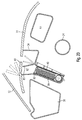
- the invention relates to an assembly consisting of a Vehicle body, a windscreen, an instrument panel with a Ventilation duct for ventilation of the windscreen and an airbag module.
- Airbags are intended to prevent a vehicle occupant from making rough contact with the vehicle Preserve vehicle structure by absorbing its kinetic energy and in effectively braking the head effectively. This requirement is special then not easy to fulfill if the vehicle occupant is not in one optimal sitting position, i.e. if he has the upper body over or towards Side bends. In such cases, the gas bag must be as far away from the occupant as possible removed on a wide front to unfold the occupant in different ways Intercept positions. This is indicated in the prior art by a elongated gas bag module reached, which is parallel to the front edge of the Instrument panel extends, as for example in DE 23 38 025 is described. In addition, there are also impairments of the Vehicle occupants through the opening mechanisms of the gas bag module, for example, opening flaps or opening covers, excluded.
- the object of the invention is therefore an assembly of the aforementioned To create the way in which the gas bag module is outside the engagement area of the vehicle occupant.
- the gas bag module between the front window and the Ventilation duct is arranged.
- the opening mechanism of the Airbag module for example a cover flap that can be torn open, can thus be arranged outside the area of engagement of the vehicle occupant.
- the arrangement of the gas bag module in the vehicle occupant seen rear area of the instrument panel a larger design Freedom for the front area of the vehicle Dashboard. It is therefore possible to design this for the vehicle interior adapt the sensitive area to the overall vehicle concept without functional requirements should be taken into account.
- the airbag module has an airbag which is folded into an airbag package, that a shot channel is provided for ejecting the gas bag, which in a Ejection opening opens through which the gas bag can be ejected, and that the gas bag module has a housing, the firing channel being limited from a first firing channel wall formed by the housing and from a second shot channel wall formed by the vehicle body.
- the Housing must therefore have only one firing channel wall, so that it is essential can be simplified, resulting in a relevant weight and Material saving leads.
- a subassembly can be seen schematically in cross section that consists of a vehicle body 10, a windscreen 12, an instrument panel 14 and a gas bag module 16.
- the vehicle body 10 encloses one Vehicle interior 18, in which a vehicle occupant 20, which is shown in FIG is indicated schematically, for example sitting on a seat 22 can.
- the vehicle body 10 has frame parts 24, a splash guard wall 26 and a vehicle floor 28.
- On the vehicle body 10 is a Disc holder 30 attached, in which the windshield 12 with their Lower edge 32 is mounted. Starting from the disc holder 30 extends the instrument panel 14 in the vehicle interior 18, whereby the Disc holder 30 and the vehicle frame 24 before the eyes of the Vehicle occupants 20 laminated.
- a ventilation duct 34 provided, with the aid of which warm air is conducted to the windscreen 12 to de-ice them or prevent them from fogging up.
- the disk holder 30 can, for example, as shown in the figures as Hollow profile made of plastic or metal.
- an indentation 36 for receiving the Lower edge 32 of the windshield 12 is formed.
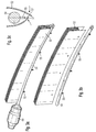
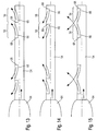
- the gas bag module 16 attached, of which in Figures 3 and 4 two different designs are shown in more detail.
- FIGS. 3a to 3e Details of the gas module according to FIG. 3 are shown in FIGS. 3a to 3e.
- the gas lance 54 is provided with lugs 55 which face down from the gas lance protrude. Openings 57 can be hooked into the lugs, the ones at the bottom End of the gas bag are provided (see in particular Figure 3c).
- the protective layer 58 can also be attached.
- the lugs 55 can be made in one piece with the gas lance or welded to it.
- the gas bag module 16 has a housing 40, which in cross section a substantially straight first shot channel wall 42 and one thereon adjoining angled fastening section 44. With this Fastening portion 44, the housing 40 is attached to the disc holder 30, and in such a way that the first firing channel wall 42 faces upwards, that is to say Instrument panel 14.
- the inside 38 of the disk holder 30 thus forms one second firing channel wall 46, whereby the two firing channel walls 42 and 46 define a shot channel 48, the discharge opening 50 to the instrument panel 14 points.
- the firing channel 48 houses an airbag 52 and one therein immersed gas lance 54, the gas lance 54 with outflow openings 56 provided and adjacent to the attachment portion 44 on the housing 40 is attached ( Figure 3).
- the gas bag 52 is folded into a package that consists of a plurality of subpackages 52a and 52b folded in different ways can exist.
- the folded package may be covered with a protective layer 58, for example in the form of a film or a fabric layer between the edges of the housing 40 extends and can be provided with a perforation 59 to tear the protective layer 58 to facilitate.
- the instrument panel 14 forms one in the area of the gas bag module 16 Cover 60 for the discharge opening 50 of the firing channel 48 to the windshield 12.
- a predetermined breaking point or Tear line may be provided, which in the event of triggering tears open the cover 60 and the gas bag 52 is allowed to exit the firing channel 48.
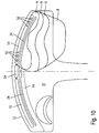
- alternative can also cover 60 in the housing 40 of the gas bag module 16, as in Figure 5 shown, or be integrated into the ventilation duct 34.
- This ventilation duct 34 can either, as in FIGS. 1 and 2 shown, integrated into the instrument panel 14 or as a separate part be trained.
- the second alternative is exemplified in FIGS.
- the ventilation duct 34 in the form of one or two elongated Channels, for example made of plastic, is provided.
- the channels open each at one end in a nozzle 62 which is connected to a feed channel of the Ventilation system can be plugged on.
- the channels can be from the Instrument panel 14 may be covered, for example in this area Can have air outlet slots.
- the moving parts of the Opening mechanism of the gas bag module 16 that is, the tearing open cover 60, far from the interaction area of the vehicle occupant 20, even if this bends over to, for example, a glove box 63 to grab. Due to the elongated and narrow construction of the gas bag module 16 ( Figures 6 and 7), the ventilation duct 34 can still be close enough to the Windscreen 12 may be arranged to perform its function.
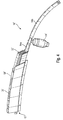
- the gas bag module 16 is advantageously in accordance with the shape of the Vehicle body 10 curved, as based on the embodiments of FIGS Figures 3, 4, and 6 to 9 can be seen.
- the curvature can in particular Course of the lower edge 32 of the front window 12 can be adjusted so that Airbag module 16 as close as possible to the front window 12 or to the window holder 30 can run.
- the gas bag module 16 due to the curvature be advantageously adapted to the design of the instrument panel 14.
- the gas lance 54 is connected to a gas generator 64 (FIG. 3), of which it can be fed with compressed gas in order to inflate the gas bag 52.
- a gas generator 64 FIG. 3
- FIG. 4 In a another design of an airbag module 16 '( Figure 4) are for the driver and Passenger side separate gas bags 52 'and gas lances 54a and 54b provided, both of which are connected to the same gas generator 64 '.
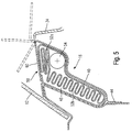
- the targeted spread of the airbag 52 can continue through shape and Arrangement of the outflow openings 56 in the gas lance 54, as in FIGS. 10 and 13 to 15 are influenced. Firstly, through the Arrangement of the outflow openings 56 at the ends of the gas lance 54 or in that the cross sections of the outflow openings 56 in these areas are made larger than in the middle, can be achieved that the gas bag 52nd spreads faster in the side areas. This is shown in FIG different propagation phases a to d of the airbag 52 indicated. A Such spreading of the airbag 52 is particularly advantageous when the vehicle occupant 20 is not in an optimal sitting position.
- the outflow openings 56 in the gas lance 54 in advantageously in the form of gill-like indentations 66.
- FIGS. 13 to 15 show such outflow openings 56.
- she consist of indentations 66 pressed into the gas lance, of which one in Longitudinal end is stamped and thus an opening 68 for Forms pipe interior.
- Outflow direction of the gas from the gas lance 54 is essentially predetermined, as indicated by the arrows in FIGS. 13 to 15. So that can escaping gas to the ends ( Figure 13) or to the center ( Figure 14 of the gas lance 54 are steered or swirled at the outflow openings 56 (FIG. 15).
- the gas lance 54 is not below the entire airbag package 52 arranged, but from the upper sub-package 52a comprising a few layers covered and to the side of the lower sub-package 52b, namely on the Vehicle interior 18 facing side.
- This arrangement achieves that when the gas bag module 16 is triggered, the few layers of the upper sub-package 52a in the direction of the windshield 12 and then the remaining layers of the lower sub-package 52b due to the unfolding Gas bag 52 are tightened, the gas bag 52 being advantageous Can unfold along the front window 12.
- the gas lance is arranged similarly, but on the outside of the vehicle facing side of the folded lower sub-package 52b, so that the The gas bag 52 unfolds in comparison to the embodiment according to FIG. 11 rather takes place along the instrument panel 14.
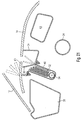
- FIG. 1 Another embodiment of an assembly according to the invention shows 16, in which reference numerals increased by 100 for already known components Find use.
- the splash guard 126 is sufficient into the vehicle interior 118 up to the instrument panel 114.
- the gas bag module 116 is not as in FIG the previous embodiments on the disc holder 130, but on the Splash guard wall 126 is attached to the vehicle interior 118 opposite side, while the ventilation duct 134 on the other side of the Splash guard 126 is located.
- the gap 170 is through a Moisture protection wall 172, which on the splash guard 126 and on Disk holder 130 is attached, completed against the engine compartment 174.
- This embodiment offers the advantage that the gas bag module 116 from Engine compartment 174 can be assembled here. This mounting option is especially with regard to the usually very bulky combined driver and Passenger modules ( Figure 4) advantageous.
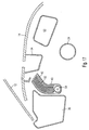
- FIG. 17 shows an assembly according to an eighth embodiment of the Invention shown.
- the housing is cranked out; the shot channel 42 extends in one different direction than the part of the housing 40 in which the gas lance 54 is arranged.
- the shot channel 42 is oriented so that it is parallel to Windshield 12 runs. This leads to less stress on the Windshield when the gas bag leaves the housing 40. Also results more space for the disc holder 30.
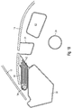
- FIG. 18 shows an assembly according to a ninth embodiment. Similar to the eighth embodiment, the housing is cranked extended so that the weft channel 42 is parallel to the windshield 12th extends. In contrast to the eighth embodiment, the housing 40 is included the area in which the gas lance 54 is arranged lies horizontally arranged the disc holder 30. This is particularly space-saving. at Activation of the gas bag emerges from a flap of the instrument panel 14 out between the windshield 12 and the ventilation duct 34 is arranged.
- FIG. 19 shows an assembly according to a tenth embodiment.
- the housing 40 is integral with the ventilation duct 34 executed, hanging below this near the Target holder 30.
- the shot channel 42 is here below the cover 60 a separating flap 80 to delimit the ventilation duct 34 is provided. This is so elastic that it is when the gas bag unfolds yields slightly, so that the firing channel widens. That way the outlet opening of the ventilation duct 34 for the exit of the gas bag be used.
- the housing 40 of the gas bag can be made in one piece with the ventilation duct 34 are formed, external reinforcing ribs being provided.
- the gas bag can be easily in the housing 40 by one Tissue cover 82 may be enclosed.
- FIG. 20 shows an assembly according to an eleventh embodiment of the Invention shown.
- the housing is 40 executed in composite construction. Part of the housing is in one piece with the ventilation duct 34, while on the disc holder 30 facing side a metal shell 84 made of sheet steel or aluminum is provided.
- FIG. 21 shows an assembly according to a twelfth embodiment shown.
- the housing 40 is here as from the ventilation duct 34 separate component made of plastic, steel or aluminum can exist and is screwed to the ventilation duct 34.
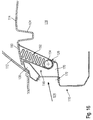
- FIG. 22 shows an assembly according to a thirteenth embodiment shown.
- the difference to that shown for example in Figure 3 Embodiment consists in that a transition tube connects to the gas lance 54 86 connects that connects the gas lance 54 to the gas generator 64.
- the Transition tube allows the gas generator 64 to be flexible and in a large size Distance from the airbag module in the vehicle to be arranged in a suitable place.
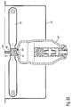
- FIGs 23 to 26 is an attachment option for one Gas generator 64 'shown as shown in Figure 4.
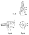
- the gas generator 64 is on a T-piece 90 connected, which has an entrance opening 91 and a transverse to it has extending output bore 92.
- a threaded pin 93 is provided on the opposite side, which are used for fastening can.
- the input opening 91 of the T-piece 90 is designed to be a Bursting membrane 94 of the gas generator 64 'can hold. In this area too the T-piece inserted into the gas generator 64 ', for example by flanging.
- the gas generator 64 inserted through an opening from below into the housing 40 and there attached by means of a pipe clamp 95.
- the gas lance 54 extends along the upper edge of the housing (see also Figure 23).
- the attachment of the housing does not have to be designed for particularly high forces, since the gas generator due to the T-piece is attached without shear.
- FIGS. 29 to 31 A variant is shown in FIGS. 29 to 31, in which the gas bag is in front the gas generator 64 is arranged (see in particular FIG. 30).
- the gas lance For this purpose, 54 is provided with outflow openings which run the gas parallel to Let the upper wall of the housing 40 emerge (horizontally in FIG right).
- the gas lance can be screwed 96 in the same way as the T-piece 90 are screwed through the top of the housing 40.
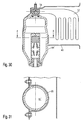
- FIG. Another variant is shown in FIG.
- the T-piece 90 with a membrane holder 97 of the gas generator 64 'crimped.
- the membrane holder 97 is provided with a groove 98 into which the material of the T-piece 90 is pushed in.
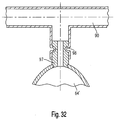
- Figure 33 is an assembly according to a fourteenth embodiment shown.
- the gas generator 64 ' is outside the Housing 40 arranged, and the gas lance 54 extends symmetrically on both sides of the T-piece 90 along the lower edge of the housing 40. Die Gas lance 54 is bent obliquely upwards at both ends. Over these ends the gas bag 52 is put over and fastened with a clamp 99.
- the gas bag begins at the ends of the gas lance 54 to unfold, in the direction indicated by the arrows. The Unfolding then progresses towards the middle.
Landscapes
- Engineering & Computer Science (AREA)
- Mechanical Engineering (AREA)
- Physics & Mathematics (AREA)
- Thermal Sciences (AREA)
- Fluid Mechanics (AREA)
- Air Bags (AREA)
- Body Structure For Vehicles (AREA)
Abstract
Description
- Figur 1 einen Querschnitt durch eine Baugruppe gemäß einer ersten Ausführungsform der Erfindung;
- Figur 2 eine vergrößerte Darstellung des Bereichs II aus Figur 1;
- Figur 3 eine teilweise geschnittene Ansicht einer ersten Bauform eines Gassackmoduls für eine erfindungsgemäße Baugruppe;
- die Figuren 3a bis 3e Details des Gassackmoduls gemäß Figur 3;
- Figur 4 eine teilweise geschnittene Ansicht einer zweiten Bauform eines Gassackmoduls für eine erfindungsgemäße Baugruppe;
- Figur 5 einen Querschnitt durch eine Baugruppe gemäß einer zweiten Ausführungsform der Erfindung;
- Figur 6 eine Ansicht von Scheibenhalter, Gassackmodul und Lüftungskanal für eine Baugruppe gemäß einer dritten Ausführungsform der Erfindung;
- Figur 7 eine Ansicht von Scheibenhalter, Frontscheibe, Gassackmodul und Lüftungskanal für eine Baugruppe gemäß einer vierten Ausführungsform der Erfindung aus einer ersten Perspektive;
- Figur 8 eine Ansicht der Komponenten aus Figur 7 aus einer zweiten Perspektive;
- Figur 9 eine Ansicht des Gassackmoduls aus Figur 7 aus einer dritten Perspektive;
- Figur 10 eine schematische Ansicht der Baugruppe aus Figur 1;
- Figur 11 einen Querschnitt durch eine Baugruppe gemäß einer fünften Ausführungsform der Erfindung;
- Figur 12 einen Querschnitt durch eine Baugruppe gemäß einer sechsten Ausführungsform der Erfindung;
- Figur 13 einen Querschnitt durch eine erste Bauform einer Gaslanze eines Gassackmoduls für eine erfindungsgemäße Baugruppe,
- Figur 14 einen Querschnitt durch eine zweite Bauform einer Gaslanze eines Gassackmoduls für eine erfindungsgemäße Baugruppe;
- Figur 15 einen Querschnitt durch eine dritte Bauform einer Gaslanze eines Gassackmoduls für eine erfindungsgemäße Baugruppe;
- Figur 16 einen Querschnitt durch eine Baugruppe gemäß einer siebten Ausführungsform der Erfindung;
- Figur 17 einen Querschnitt durch eine Baugruppe gemäß einer achten Ausführungsform der Erfindung;
- Figur 18 einen Querschnitt durch eine Baugruppe gemäß einer neunten Ausführungsform der Erfindung;
- Figur 19 einen Querschnitt durch eine Baugruppe gemäß einer zehnten Ausführungsform der Erfindung;
- Figur 20 einen Querschnitt durch eine Baugruppe gemäß einer elften Ausführungsform der Erfindung;
- Figur 21 einen Querschnitt durch eine Baugruppe gemäß einer zwölften Ausführungsform der Erfindung;
- Figur 22 in einer schematischen, perspektivischen Ansicht eine Baugruppe gemäß einer dreizehnten Ausführungsform der Erfindung;
- Figur 23 in einer teilgeschnittenen Ansicht im Detail eine Anbringungsart eines Gasgenerators, wie sie bei der Bauform gemäß Figur 4 genutzt werden kann;
- Figur 24 in einer Schnittansicht das T-Stück, das bei Figur 23 zur Anbringung des Gasgenerators verwendet wird;
- Figur 25 eine weitere Schnittansicht des T-Stücks;
- Figur 26 eine Draufsicht des T-Stücks;
- Figur 27 in einer Schnittansicht die Anbringungsart von Figur 23;
- Figur 28 den Gasgenerator von Figur 27 in einem Schnitt entlang der Ebene A-A von Figur 27;
- Figur 29 in einer teilgeschnittenen Ansicht eine weitere Anbringungsart eines Gasgenerators;
- Figur 30 in einer schematischen Schnittansicht die Anbringungsart von Figur 29;
- Figur 31 den Gasgenerator von Figur 30 in einem Schnitt entlang der Ebene A-A von Figur 30;
- Figur 32 in einer Schnittansicht eine weitere Anbringungsart eines Gasgenerators; und
- Figur 33 in einer teilgeschnittenen Ansicht eine Baugruppe gemäß einer vierzehnten Ausführungsform der Erfindung.
Claims (24)
- Baugruppe bestehend aus einer Fahrzeugkarosserie (10; 110), einer Frontscheibe (12; 112), einer Instrumententafel (14; 114) mit einem Lüftungskanal (34; 134) zum Belüften der Frontscheibe und einem Gassackmodul (16; 16'; 116), dadurch gekennzeichnet, daß das Gassackmodul (16; 16'; 116) zwischen der Frontscheibe (12; 112) und dem Lüftungskanal (34; 134) angeordnet ist.
- Baugruppe nach Anspruch 1, dadurch gekennzeichnet, daß das Gassackmodul (16; 16'; 116) einen Gassack (52; 52'; 152) aufweist, der zu einem Gassackpaket gefaltet ist, und daß ein Schußkanal (48; 148) zum Ausstoßen des Gassackes vorgesehen ist, der in eine Ausstoßöffnung (50) mündet, durch die der Gassack ausgestoßen werden kann.
- Baugruppe nach Anspruch 2, dadurch gekennzeichnet, daß das Gassackmodul (16; 16'; 116) ein Gehäuse (40; 40'; 140) aufweist und der Schußkanal (48; 148) begrenzt ist von einer ersten Schußkanalwand (42; 142), die von dem Gehäuse gebildet ist, und von einer zweiten Schußkanalwand (46; 146), die von der Fahrzeugkarosserie (10; 110) gebildet ist.
- Baugruppe nach Anspruch 3, dadurch gekennzeichnet, daß die Fahrzeugkarosserie (10) einen Scheibenhalter (30) für die Frontscheibe (12) aufweist, wobei die zweite Schußkanalwand (46) von dem Scheibenhalter (30) gebildet ist.
- Baugruppe nach Anspruch 3, dadurch gekennzeichnet, daß die Fahrzeugkarosserie (110) eine Spritzschutzwand (126) aufweist, wobei die zweite Schußkanalwand (146) von der Spritzschutzwand (126) gebildet ist.
- Baugruppe nach einem der Ansprüche 2 bis 5, dadurch gekennzeichnet, daß das Gassackmodul eine Gaslanze (54; 54a, 54b; 154) aufweist, durch die Gas in den Gassack (52; 52'; 152) geleitet werden kann.
- Baugruppe nach Anspruch 6, dadurch gekennzeichnet, daß die Gaslanze (54) mit kiemenartigen Ausströmöffnungen (56) versehen ist.
- Baugruppe nach Anspruch 7, dadurch gekennzeichnet, daß die kiemenartigen Ausströmöffnungen (56) so ausgerichtet sind, daß das aus der Gaslanze (54) ausströmende Gas zu den Enden der Gaslanze (54) hin strömt.
- Baugruppe nach Anspruch 7, dadurch gekennzeichnet, daß die kiemenartigen Ausströmöffnungen (56) so ausgerichtet sind, daß das aus der Gaslanze (54) ausströmende Gas zur Mitte der Gaslanze (54) hin strömt.
- Baugruppe nach Anspruch 7, dadurch gekennzeichnet, daß die kiemenartigen Ausströmöffnungen (56) so ausgerichtet sind, daß das aus der Gaslanze (54) ausströmende Gas verwirbelt wird.
- Baugruppe nach Anspruch 6, dadurch gekennzeichnet, daß die Gaslanze (54) zwischen dem Gassackpaket und dem Lüftungskanal (34) angeordnet ist.
- Baugruppe nach Anspruch 6, dadurch gekennzeichnet, daß die Gaslanze (54) zwischen dem Gassackpaket und der Frontscheibe (12) angeordnet ist.
- Baugruppe nach einem der Ansprüche 6 bis 12 , dadurch gekennzeichnet, daß das Gassackpaket zwei Teilpakete umfaßt, von denen das erste Teilpaket (52a) auf eine erste Art gefaltet ist und näher zur Ausstoßöffnung (50) angeordnet ist, während das zweite Teilpaket (52b) auf eine zweite Art gefaltet ist und ferner zur Ausstoßöffnung angeordnet ist.
- Baugruppe nach Anspruch 13, dadurch gekennzeichnet, daß das erste Teilpaket (52a) zwischen der Ausstoßöffnung und der Gaslanze (54) angeordnet ist.
- Baugruppe nach einem der Ansprüche 2 bis 14, dadurch gekennzeichnet, daß der Schußkanal (48) gegenüber dem Rest des Gehäuses (40) abgekröpft ist, so daß er parallel zur Windschutzscheibe (12) verläuft.
- Baugruppe nach einem der vorhergehenden Ansprüche, dadurch gekennzeichnet, daß das Gassackmodul (16) für Fahrer- und Beifahrerseite getrennte Gasgeneratoren (64) aufweist.
- Baugruppe nach einem der Ansprüche 1 bis 15, dadurch gekennzeichnet, daß das Gassackmodul (16') für Fahrer- und Beifahrerseite einen gemeinsamen Gasgenerator (64') aufweist.
- Baugruppe nach einem der vorhergehenden Ansprüche, dadurch gekennzeichnet, daß das Gehäuse (40) am Lüftungskanal (34) angeordnet ist.
- Baugruppe nach Anspruch 18, dadurch gekennzeichnet, daß das Gehäuse (40) einstückig mit dem Lüftungskanal (34) ausgebildet ist.
- Baugruppe nach Anspruch 18, dadurch gekennzeichnet, daß das Gehäuse (40) an den Lüftungskanal (34) angeschraubt ist.
- Baugruppe nach einem der vorhergehenden Ansprüche, dadurch gekennzeichnet, daß zwischen der Gaslanze (54) und dem Gasgenerator (64) ein Übergangsrohr (86) angeordnet ist.
- Baugruppe nach einem der vorhergehenden Ansprüche, dadurch gekennzeichnet, daß die Gaslanze (54) mit Nasen (55) versehen ist, in die der Gassack (52) eingehängt ist.
- Baugruppe nach einem der vorhergehenden Ansprüche, dadurch gekennzeichnet, daß ein T-Stück 90 am Gasgenerator (64; 64') angeordnet ist, das gleichzeitig als Halter für eine Berstmembran (94) dient.
- Baugruppe nach einem der vorhergehenden Ansprüche, dadurch gekennzeichnet, daß ein T-Stück (90) vorgesehen ist, das mit dem Gasgenerator (64; 64') vercrimpt ist.
Applications Claiming Priority (2)
| Application Number | Priority Date | Filing Date | Title |
|---|---|---|---|
| DE10131120 | 2001-06-28 | ||
| DE10131120A DE10131120A1 (de) | 2001-06-28 | 2001-06-28 | Baugruppe bestehend aus Fahrzeugkarosserie, Frontscheibe, Instrumententafel und Gassackmodul |
Publications (2)
| Publication Number | Publication Date |
|---|---|
| EP1270341A2 true EP1270341A2 (de) | 2003-01-02 |
| EP1270341A3 EP1270341A3 (de) | 2004-02-11 |
Family
ID=7689724
Family Applications (1)
| Application Number | Title | Priority Date | Filing Date |
|---|---|---|---|
| EP02012414A Withdrawn EP1270341A3 (de) | 2001-06-28 | 2002-06-07 | Baugruppe bestehend aus Fahrzeugkarosserie, Frontscheibe, Instrumententafel und Gassackmodul |
Country Status (3)
| Country | Link |
|---|---|
| US (1) | US20030001366A1 (de) |
| EP (1) | EP1270341A3 (de) |
| DE (1) | DE10131120A1 (de) |
Cited By (9)
| Publication number | Priority date | Publication date | Assignee | Title |
|---|---|---|---|---|
| DE20300500U1 (de) | 2003-01-13 | 2003-06-18 | TRW Occupant Restraint Systems GmbH & Co. KG, 73553 Alfdorf | Gasgenerator und Gassackmodul |
| WO2004045920A1 (de) * | 2002-11-15 | 2004-06-03 | Autoliv Development Ab | Instrumententafel für ein kraftfahrzeug mit einer in einer lüftungsanordnung integrierten airbageinrichtung |
| JP2005145441A (ja) * | 2003-11-12 | 2005-06-09 | Hyundai Motor Co Ltd | インビジブルエアーバック装置 |
| EP1419941A3 (de) * | 2002-11-15 | 2005-09-14 | TRW Occupant Restraint Systems GmbH & Co. KG | Baugruppe bestehend aus Fahrzeugkarosserieteil und einem Gassackmodul |
| US7322595B2 (en) | 2002-06-07 | 2008-01-29 | Autoliv Development Ab | Electrically insulated fixing device for an airbag module |
| DE102007019394A1 (de) * | 2007-04-23 | 2008-10-30 | Faurecia Innenraum Systeme Gmbh | Sicherheitseinrichtung für ein Kraftfahrzeug |
| EP2106942A1 (de) * | 2008-04-03 | 2009-10-07 | IAC Group GmbH | Airbag-Anordnung für ein Kraftfahrzeug |
| EP3127757A4 (de) * | 2014-03-31 | 2018-02-28 | Autoliv Development AB | Airbagvorrichtung für fahrzeug |
| US10421427B2 (en) | 2017-02-03 | 2019-09-24 | Toyoda Gosei Co., Ltd. | Occupant protection device |
Families Citing this family (32)
| Publication number | Priority date | Publication date | Assignee | Title |
|---|---|---|---|---|
| DE10249375A1 (de) * | 2002-10-23 | 2004-05-19 | Trw Occupant Restraint Systems Gmbh & Co. Kg | Gassackmodul mit Gaslanze |
| DE10252285A1 (de) * | 2002-11-06 | 2004-05-27 | Takata-Petri Ag | Scharnier zur Anbindung einer Klappe, insbesondere einer Motorhaube, an einem Fahrzeugkörper |
| US6991253B2 (en) * | 2003-04-11 | 2006-01-31 | Delphi Technologies, Inc. | Air bag assembly having controlled cushion deployment |
| GB2420099A (en) * | 2004-11-10 | 2006-05-17 | Autoliv Dev | Air-bag unit in vehicle dashboard |
| GB2422357B (en) * | 2005-01-25 | 2008-03-12 | Autoliv Dev | Improvments in or relating to a safety arrangement |
| US7845682B2 (en) * | 2005-04-27 | 2010-12-07 | Autoliv Asp, Inc. | Airbag cushion folding methods |
| US7942442B2 (en) * | 2005-04-27 | 2011-05-17 | Autoliv Asp, Inc. | Airbag cushion folding methods |
| US7837227B2 (en) * | 2006-06-16 | 2010-11-23 | Autoliv Development Ab | Air-bag housing |
| DE102007052719A1 (de) * | 2007-11-06 | 2009-05-07 | GM Global Technology Operations, Inc., Detroit | Airbagdeckel und Airbagdeckelanordnung |
| DE102007052974A1 (de) * | 2007-11-07 | 2009-05-14 | GM Global Technology Operations, Inc., Detroit | Rückhaltesystem für vordere Fahrzeuginsassen |
| DE102007052973A1 (de) * | 2007-11-07 | 2009-05-14 | GM Global Technology Operations, Inc., Detroit | Airbagmodul, Airbagmodulanordnung und Befestigungsverfahren |
| US7926844B2 (en) * | 2008-04-10 | 2011-04-19 | Autoliv Asp, Inc. | Airbag assembly and method of packing |
| DE102008062267A1 (de) * | 2008-12-15 | 2010-06-17 | GM Global Technology Operations, Inc., Detroit | Kraftfahrzeug mit Kopfairbag |
| DE102009012899A1 (de) * | 2009-03-12 | 2010-09-16 | GM Global Technology Operations, Inc., Detroit | Verkleidungsteil mit Airbagklappe sowie Airbaganordnung mit dem Verkleidungsteil |
| DE102009024142B4 (de) * | 2009-06-04 | 2016-05-12 | TAKATA Aktiengesellschaft | Airbagmodul für ein Kraftfahrzeug |
| US8226118B2 (en) * | 2009-08-05 | 2012-07-24 | Autoliv Asp, Inc. | Safety venting with passively closeable vents |
| US8407968B2 (en) * | 2009-10-16 | 2013-04-02 | Autoliv Asp, Inc. | Method of packaging an inflatable airbag cushion including a wrapper and deployment flap |
| DE102011007668B4 (de) * | 2011-04-19 | 2019-04-25 | Shanghai Yanfeng Jinqiao Automotive Trim Systems Co., Ltd. | Instrumententafel für ein Fahrzeug |
| DE102011106555A1 (de) | 2011-07-05 | 2013-01-10 | Volkswagen Aktiengesellschaft | Armaturentafel eines Kraftfahrzeugs |
| US8540276B2 (en) | 2011-11-07 | 2013-09-24 | Autoliv Asp, Inc. | Inflatable knee airbag assemblies with cushion fold pattern |
| US9409538B2 (en) * | 2013-12-30 | 2016-08-09 | GM Global Technology Operations LLC | Integrated airbag and HVAC assembly |
| US10040414B1 (en) * | 2017-03-15 | 2018-08-07 | Nio Usa, Inc. | Dash panel exterior mounted passenger airbag |
| US10343643B2 (en) | 2017-03-29 | 2019-07-09 | Nio Nextev Limited | Airbag deployment trajectory control mechanism and method |
| US11021126B1 (en) * | 2017-06-30 | 2021-06-01 | Apple Inc. | Windshield area intrusion control |
| US10518732B2 (en) * | 2017-08-04 | 2019-12-31 | Byton Limited | Airbag devices designed to utilize a reduced interior surface area of a vehicle |
| US10583855B2 (en) | 2017-09-05 | 2020-03-10 | Byton Gmbh | Steering device for a vehicle, in particular an electric vehicle |
| US10507783B2 (en) | 2017-09-13 | 2019-12-17 | Nio Usa, Inc. | Adaptive backup structure for airbag support |
| DE102017124579A1 (de) * | 2017-10-20 | 2019-04-25 | Dalphi Metal Espana, S.A. | Fahrzeuginsassen-rückhaltesystem mit einem gassack |
| US11407436B2 (en) | 2019-03-04 | 2022-08-09 | Byton North America Corporation | Steering wheel with fixed center |
| GB2585651B (en) * | 2019-07-09 | 2021-11-03 | Ford Global Tech Llc | A vehicle airbag assembly and associated method of forming |
| DE102021003865A1 (de) | 2021-07-27 | 2022-07-07 | Mercedes-Benz Group AG | Vorrichtung und Verfahren zur Erwärmung einer Windschutzscheibe eines Fahrzeugs |
| US11535188B1 (en) * | 2021-08-31 | 2022-12-27 | Ford Global Technologies, Llc | Airbag with integrated air duct |
Citations (1)
| Publication number | Priority date | Publication date | Assignee | Title |
|---|---|---|---|---|
| DE2338025A1 (de) | 1972-08-25 | 1974-03-07 | Gen Motors Corp | Insassen-rueckhaltesystem |
Family Cites Families (7)
| Publication number | Priority date | Publication date | Assignee | Title |
|---|---|---|---|---|
| US3887109A (en) * | 1974-05-13 | 1975-06-03 | Gen Motors Corp | Valve arrangement for a vehicular inflatable cushion |
| DE4225709C2 (de) * | 1992-08-04 | 1994-11-03 | Daimler Benz Ag | Rückhaltesystem mit Gassack |
| EP0646500B1 (de) * | 1993-09-29 | 1997-06-18 | Mercedes-Benz Ag | Instrumententafel für ein Kraftfahrzeug |
| GB9423776D0 (en) * | 1994-11-25 | 1995-01-11 | Acg Deutschland Gmbh | Dashboard assembly |
| US5533748A (en) * | 1994-12-01 | 1996-07-09 | Morton International, Inc. | Invisible instrument panel or dashboard airbag cover door |
| US5992877A (en) * | 1998-04-30 | 1999-11-30 | Textron Automotive Company, Inc. | Window mounted air bag |
| JP2001122070A (ja) * | 1999-10-22 | 2001-05-08 | Takata Corp | エアバック装置及びインストルメントパネル |
-
2001
- 2001-06-28 DE DE10131120A patent/DE10131120A1/de not_active Ceased
-
2002
- 2002-06-07 EP EP02012414A patent/EP1270341A3/de not_active Withdrawn
- 2002-06-18 US US10/173,758 patent/US20030001366A1/en not_active Abandoned
Patent Citations (1)
| Publication number | Priority date | Publication date | Assignee | Title |
|---|---|---|---|---|
| DE2338025A1 (de) | 1972-08-25 | 1974-03-07 | Gen Motors Corp | Insassen-rueckhaltesystem |
Cited By (13)
| Publication number | Priority date | Publication date | Assignee | Title |
|---|---|---|---|---|
| US7322595B2 (en) | 2002-06-07 | 2008-01-29 | Autoliv Development Ab | Electrically insulated fixing device for an airbag module |
| US7325827B2 (en) | 2002-11-15 | 2008-02-05 | Autoliv Development Ab | Instrument panel for a motor vehicle having an airbag device integrated in a ventilation arrangement |
| WO2004045920A1 (de) * | 2002-11-15 | 2004-06-03 | Autoliv Development Ab | Instrumententafel für ein kraftfahrzeug mit einer in einer lüftungsanordnung integrierten airbageinrichtung |
| DE10253185A1 (de) * | 2002-11-15 | 2004-06-03 | Autoliv Development Ab | Instrumententafel für ein Kraftfahrzeug mit einer in einer Lüftungsanordnung integrierten Airbageinrichtung |
| EP1419941A3 (de) * | 2002-11-15 | 2005-09-14 | TRW Occupant Restraint Systems GmbH & Co. KG | Baugruppe bestehend aus Fahrzeugkarosserieteil und einem Gassackmodul |
| DE20300500U1 (de) | 2003-01-13 | 2003-06-18 | TRW Occupant Restraint Systems GmbH & Co. KG, 73553 Alfdorf | Gasgenerator und Gassackmodul |
| JP2005145441A (ja) * | 2003-11-12 | 2005-06-09 | Hyundai Motor Co Ltd | インビジブルエアーバック装置 |
| DE102007019394A1 (de) * | 2007-04-23 | 2008-10-30 | Faurecia Innenraum Systeme Gmbh | Sicherheitseinrichtung für ein Kraftfahrzeug |
| DE102007019394B4 (de) * | 2007-04-23 | 2013-01-24 | Faurecia Innenraum Systeme Gmbh | Sicherheitseinrichtung für ein Kraftfahrzeug |
| EP2106942A1 (de) * | 2008-04-03 | 2009-10-07 | IAC Group GmbH | Airbag-Anordnung für ein Kraftfahrzeug |
| EP3127757A4 (de) * | 2014-03-31 | 2018-02-28 | Autoliv Development AB | Airbagvorrichtung für fahrzeug |
| EP3486124A1 (de) * | 2014-03-31 | 2019-05-22 | Autoliv Development AB | Airbagvorrichtung für fahrzeug |
| US10421427B2 (en) | 2017-02-03 | 2019-09-24 | Toyoda Gosei Co., Ltd. | Occupant protection device |
Also Published As
| Publication number | Publication date |
|---|---|
| DE10131120A1 (de) | 2003-02-06 |
| EP1270341A3 (de) | 2004-02-11 |
| US20030001366A1 (en) | 2003-01-02 |
Similar Documents
| Publication | Publication Date | Title |
|---|---|---|
| EP1270341A2 (de) | Baugruppe bestehend aus Fahrzeugkarosserie, Frontscheibe, Instrumententafel und Gassackmodul | |
| EP0999101B1 (de) | Gassack-Seitenaufprall-Schutzeinrichtung | |
| DE4137926C2 (de) | Abdeckung für ein Airbagmodul in einem Kraftfahrzeug | |
| EP1199227B1 (de) | Baugruppe bestehend aus Sitzlehne und Gassack-Modul | |
| WO2014096266A2 (de) | Seitenairbag für kraftfahrzeuge | |
| EP1919738A1 (de) | Airbageinrichtung für ein kraftfahrzeug | |
| DE102005010024B4 (de) | Fahrzeugtürverkleidung und Verfahren zu deren Herstellung | |
| DE10020929C5 (de) | Airbagmodul | |
| EP1106445A1 (de) | In ein Innenverkleidungsteil für Kraftfahrzeuge integriertes Airbag-System | |
| DE10063473B4 (de) | Dachholm-Verkleidung für aufblasbares Rückhaltesystem | |
| EP1185441B1 (de) | Sicherheitsabdeckung für einen airbag | |
| DE19745872B4 (de) | Airbageinrichtung | |
| EP1438218B1 (de) | Airbaganordnung in einem fahrzeug, insbesondere einem kraftfahrzeug | |
| EP1412232A1 (de) | Insassenrückhaltesystem im fondbereich eines kraftfahrzeugs | |
| EP1419941A2 (de) | Baugruppe bestehend aus Fahrzeugkarosserieteil und einem Gassackmodul | |
| DE102006027588A1 (de) | Beifahrerseitige Insassenschutzvorrichtung | |
| DE102006051218A1 (de) | Fahrzeuginsassen-Rückhaltevorrichtung mit Gassack | |
| DE10023651B4 (de) | In ein Innenverkleidungsteil für Kraftfahrzeuge integriertes Airbag-System | |
| EP1088711B1 (de) | Beifahrer-Airbagmodul für Kraftfahrzeuge | |
| DE10253402A1 (de) | Baugruppe bestehend aus Fahrzeugkarsosserieteil und Gassackmodul | |
| DE10056961A1 (de) | Aufprallschutzvorrichtung | |
| DE10039802A1 (de) | Sicherheitseinrichtung für die Insassen eines Fahrzeugs, insbesondere eines Kraftfahrzeugs | |
| DE10163686A1 (de) | Airbaganordnung in einem Fahrzeug, insbesondere einem Kraftfahrzeug | |
| DE10111597A1 (de) | Insassenschutzvorrichtung für ein Fahrzeug, insbesondere für ein Kraftfahrzeug | |
| DE102004044715A1 (de) | Rückenlehne für einen Fahrzeugsitz |
Legal Events
| Date | Code | Title | Description |
|---|---|---|---|
| PUAI | Public reference made under article 153(3) epc to a published international application that has entered the european phase |
Free format text: ORIGINAL CODE: 0009012 |
|
| AK | Designated contracting states |
Kind code of ref document: A2 Designated state(s): AT BE CH CY DE DK ES FI FR GB GR IE IT LI LU MC NL PT SE TR |
|
| AX | Request for extension of the european patent |
Free format text: AL;LT;LV;MK;RO;SI |
|
| PUAL | Search report despatched |
Free format text: ORIGINAL CODE: 0009013 |
|
| AK | Designated contracting states |
Kind code of ref document: A3 Designated state(s): AT BE CH CY DE DK ES FI FR GB GR IE IT LI LU MC NL PT SE TR |
|
| AX | Request for extension of the european patent |
Extension state: AL LT LV MK RO SI |
|
| 17P | Request for examination filed |
Effective date: 20040716 |
|
| AKX | Designation fees paid |
Designated state(s): DE ES FR IT |
|
| RBV | Designated contracting states (corrected) |
Designated state(s): DE ES FR IT |
|
| 17Q | First examination report despatched |
Effective date: 20070115 |
|
| STAA | Information on the status of an ep patent application or granted ep patent |
Free format text: STATUS: THE APPLICATION IS DEEMED TO BE WITHDRAWN |
|
| 18D | Application deemed to be withdrawn |
Effective date: 20070526 |