EP1270376A2 - Vorderwagenaufbau für ein Fahrzeug - Google Patents
Vorderwagenaufbau für ein Fahrzeug Download PDFInfo
- Publication number
- EP1270376A2 EP1270376A2 EP02014469A EP02014469A EP1270376A2 EP 1270376 A2 EP1270376 A2 EP 1270376A2 EP 02014469 A EP02014469 A EP 02014469A EP 02014469 A EP02014469 A EP 02014469A EP 1270376 A2 EP1270376 A2 EP 1270376A2
- Authority
- EP
- European Patent Office
- Prior art keywords
- vehicle
- wiper
- wiper motor
- bulkhead
- motor
- Prior art date
- Legal status (The legal status is an assumption and is not a legal conclusion. Google has not performed a legal analysis and makes no representation as to the accuracy of the status listed.)
- Granted
Links
- 238000006243 chemical reaction Methods 0.000 claims description 5
- 230000003313 weakening effect Effects 0.000 claims description 3
- 229910000838 Al alloy Inorganic materials 0.000 claims description 2
- 238000000465 moulding Methods 0.000 claims description 2
- 238000010521 absorption reaction Methods 0.000 claims 6
- 239000000956 alloy Substances 0.000 claims 1
- 230000002452 interceptive effect Effects 0.000 claims 1
- 238000000034 method Methods 0.000 claims 1
- 230000002787 reinforcement Effects 0.000 description 8
- 239000011521 glass Substances 0.000 description 3
- 230000005540 biological transmission Effects 0.000 description 2
- 239000000463 material Substances 0.000 description 2
- 230000004048 modification Effects 0.000 description 2
- 238000012986 modification Methods 0.000 description 2
- 238000005452 bending Methods 0.000 description 1
- 239000000470 constituent Substances 0.000 description 1
- 230000000694 effects Effects 0.000 description 1
- 238000004519 manufacturing process Methods 0.000 description 1
- 229910052751 metal Inorganic materials 0.000 description 1
- 239000002184 metal Substances 0.000 description 1
- 238000005192 partition Methods 0.000 description 1
- 230000001737 promoting effect Effects 0.000 description 1
- 230000035939 shock Effects 0.000 description 1
- 239000000725 suspension Substances 0.000 description 1
Images



Classifications
-
- B—PERFORMING OPERATIONS; TRANSPORTING
- B62—LAND VEHICLES FOR TRAVELLING OTHERWISE THAN ON RAILS
- B62D—MOTOR VEHICLES; TRAILERS
- B62D21/00—Understructures, i.e. chassis frame on which a vehicle body may be mounted
- B62D21/15—Understructures, i.e. chassis frame on which a vehicle body may be mounted having impact absorbing means, e.g. a frame designed to permanently or temporarily change shape or dimension upon impact with another body
-
- B—PERFORMING OPERATIONS; TRANSPORTING
- B60—VEHICLES IN GENERAL
- B60S—SERVICING, CLEANING, REPAIRING, SUPPORTING, LIFTING, OR MANOEUVRING OF VEHICLES, NOT OTHERWISE PROVIDED FOR
- B60S1/00—Cleaning of vehicles
- B60S1/02—Cleaning windscreens, windows or optical devices
- B60S1/04—Wipers or the like, e.g. scrapers
- B60S1/0488—Wiper arrangement for crash protection or impact absorption
-
- B—PERFORMING OPERATIONS; TRANSPORTING
- B62—LAND VEHICLES FOR TRAVELLING OTHERWISE THAN ON RAILS
- B62D—MOTOR VEHICLES; TRAILERS
- B62D25/00—Superstructure or monocoque structure sub-units; Parts or details thereof not otherwise provided for
- B62D25/08—Front or rear portions
- B62D25/081—Cowls
-
- B—PERFORMING OPERATIONS; TRANSPORTING
- B60—VEHICLES IN GENERAL
- B60S—SERVICING, CLEANING, REPAIRING, SUPPORTING, LIFTING, OR MANOEUVRING OF VEHICLES, NOT OTHERWISE PROVIDED FOR
- B60S1/00—Cleaning of vehicles
- B60S1/02—Cleaning windscreens, windows or optical devices
- B60S1/04—Wipers or the like, e.g. scrapers
- B60S1/043—Attachment of the wiper assembly to the vehicle
- B60S1/0433—Attachement of a wiper modular assembly to the vehicle
Definitions
- the present invention relates to a front body structure of a vehicle (such as a "car") in which an impact energy generated during a crash can be absorbed effectively by a front bulkhead, therefore promoting passenger safety. More particularly, the present invention relates to the front body structure in which wiper units are arranged on the front bulkhead such that the wiper units do not interfere with a collapse of the front bulkhead during a collision.
- a front bulkhead is arranged along a lower edge portion of front windshield of a vehicle in a widthwise direction thereof so as to partition an engine room from a passenger compartment.
- a concave portion is opened upwardly and formed in the front bulkhead.
- a wiper unit is provided in the concave portion.
- a modular wiper unit disclosed in Japanese Utility Model Examined Publication No. Hei. 8-6641, for example, is often employed.
- a motor bracket used to fix the wiper motor to the front bulkhead is fixed to the inside of the concave portion of the bulkhead such that the motor bracket extends in the longitudinal direction of the vehicle.
- the motor bracket since the motor bracket is fixed to the concave portion of the bulkhead such that the motor bracket extends in the longitudinal direction, the motor bracket acts inevitably as a reinforcement to the bulkhead.
- the wiper motor since the wiper motor is arranged at a lower position than that of upper surfaces of a strut towers that are arranged on both right and left sides of the front bulkhead, the wiper motor interferes with retreating strut towers to disturb the crash of the bulkhead. For this reason, the portion of the bulkhead to which the wiper motor is arranged becomes difficult to be locally crashed.
- the effect of absorbing the impact energy generated by the deformation of the bulkhead cannot be sufficiently achieved.
- the wiper motor since the wiper motor has a rigid body, a large reaction force is generated by the wiper motor when the impact load is applied to the wiper motor from the upper side of the vehicle. Therefore, the structure of the related art is less than ideal for reducing or eliminating the transmission of the impact energy to the passenger compartment.
- the present invention has been made in view of above circumstances, and it is an object of the present invention to provide a front body structure of a vehicle that can effectively absorb an impact energy which is transmitted to a rear side of the vehicle, by accelerating a crash of a bulkhead by an impact load applied during a collision of the vehicle.
- the present invention is for effectively protecting passengers from an impact applied during the collision, and also for absorbing the impact energy to prevent a generation of a large reaction force even when the impact load is applied to a wiper motor from an upper side of the vehicle body.
- the present invention provides a body structure of the vehicle comprising the bulkhead including a concave portion opened upwardly.
- the concave portion has front and rear wall surfaces and a wiper unit having a wiper motor is disposed between the front and rear wall surfaces of the concave portion. Further, the wiper motor is also disposed at a higher position than that of upper surfaces of strut towers of the vehicle.
- the strut towers are moved toward the rear side of the vehicle by the impact energy at the time of the frontal crash to push the bulkhead.
- the wiper motor is arranged at the higher position than that of the upper surfaces of the strut towers, such retreating strut towers can accelerate the crash of the bulkhead toward the rear side of the vehicle without an interference from the wiper motor.
- the wiper motor is fixed to the front bulkhead via a motor bracket, an inclined portion of which is bent downwardly and formed in front of the wiper motor.
- a lower end of the inclined portion is fixed to a front portion of the concave portion of the front bulkhead, and a weakening portion is provided in the inclined portion. Therefore, the crash of the bulkhead toward the rear side of the vehicle by the frontal crash can be accelerated even further.
- the motor bracket can be easily broken if the impact load is applied to the wiper motor from the upper side of the vehicle. As a result, the impact energy can be absorbed effectively.
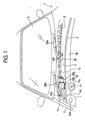
- FIG.1 is a perspective view showing a front portion of a vehicle except for a front hood and a cowl panel.
- FIG.2 is the perspective view showing a right side portion of the front portion in the situation that the front hood is opened.
- reference 1 denotes a front body portion of a vehicle.
- Front wheel aprons 2 are provided on both sides of the front body portion 1 in a vehicle widthwise direction.
- a longitudinal wall is formed on both sides of an engine room by the front wheel apron 2 in the vehicle widthwise direction.
- toe boards are arranged under a front bulkhead 3.
- the front bulkhead 3 is formed in a concave shape that is opened upwardly.
- a reinforcement 5 is arranged at the back of the front bulkhead 3 along the widthwise direction.
- An air duct 6 that extends in the widthwise direction is formed by a reinforcement 5 and a rear wall surface 3a of the front bulkhead 3.
- a concave portion 7 opened upwardly is formed by a front wall surface 3b of the front bulkhead 3 and a front wall surface 5a of the reinforcement 5.
- a lower edge portion of a front glass (windshield) 8 is fixed to an upper surface of the reinforcement 5, and an upper surface of the concave portion 7 is closed by a cowl panel 9.
- a front edge portion 9a of the cowl panel 9 is fixed to an upper end surface of the front wall surface 3b of the front bulkhead 3 and a rear edge portion 9b is fixed to a lower edge portion of the front glass 8. Further, a bent portion 9c that can be bent upwardly is formed in the longitudinally middle portion of the cowl panel 9 along the vehicle widthwise direction.
- strut towers 10 are arranged in front of the front bulkhead 3 and on both sides thereof in the vehicle widthwise direction and on the inside of the front wheel apron 2.
- FIGs. 1 and 2 only the right strut tower 10 is illustrated.
- a strut fitting plane 10a to a lower surface of which a strut upper end of a front suspension is fixed via such an elastic member as a rubber is fixed.
- rear portions of the strut towers 10 are coupled to both sides of the front wall surface 3b of the front bulkhead 3.
- a reference 11 denotes a brake masterback which integrally includes a brake master cylinder 11a and of which rear surface is supported by the toe board (not shown).
- a reference 26 in FIG.2 is a front hood.
- a modular wiper unit (abbreviated as a "wiper unit” hereinafter) 12 is installed in the concave portion 7 formed in the front bulkhead 3.
- a wiper unit 12 is explained with reference to FIG.3 hereunder.
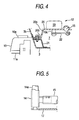
- pivot holders 13, 14 are arranged on both sides of the wiper unit 12, and both pivot holders 13, 14 are fixed integrally to both ends of a connection pipe 15 respectively by caulking, or the like (see FIG.5).
- left and right pivot shafts 13a, 14a are supported rotatably to the pivot holders 13, 14 respectively.
- left and right wiper levers 16, 17 are pivotably coupled to both pivot shafts 13a, 14a respectively, and both wiper levers 16, 17 are connected via a wiper rod 18.
- a motor bracket 20 to an upper surface of which a wiper motor unit 19 is fixed is arranged in front of the right side (the driver's seat side) of the body.
- a rear portion of the motor bracket 20 is fixed to the connection pipe 15 by caulking, or the like.
- an inclined portion 20a that is inclined downwardly is formed integrally and positioned ahead of the portion to which the wiper motor unit 19 of the motor bracket 20 is fixed.
- a flange portion 20b is formed integrally with the inclined portion 20a.
- the flange portion 20b is fixed to a supporting bracket 21 fixed to the front portion of the front bulkhead 3.
- a hole portion 20c, as a weakening portion is opened laterally, such as in an oblong shape, in the inclined portion 20a of the motor bracket 20.
- the motor bracket 20 may be die-cast molded using, for example, aluminum alloy, or the like as the material, and have relatively hard and fragile material properties. Accordingly, if a load is applied to the flange portion 20b from the front side of the body, a bending moment is concentrated into the edge portion between the flange portion 20b and the inclined portion 20a, or the edge portion between the inclined portion 20a and the upper surface, and thus any one of the edge portions is subjected to brittle fracture.
- the load is applied to the motor bracket 20 from the upper side, the stress is concentrated into the periphery of the hole portion 20c since the hole portion 20c is cut through in the inclined portion 20a, and thus, the inclined portion 20a is subjected to brittle fracture from the periphery of the hole portion 20c.
- the wiper motor unit 19 has a motor main body 19a and a reduction gear 19b integrally combined.
- a motor lever 22 that is coupled to an output shaft 19c of the reduction gear 19b is connected to a left wiper lever 16 via a motor rod 23.
- the pivot holders 13, 14 of the wiper unit 12 are fastened to a bracket (not shown), which is provided to the reinforcement 5 (or the body frame) to project therefrom, by the bolts and are fixed thereto.
- the wiper motor unit 19 is fitted at a higher position than or above that of the upper surfaces of the strut tower 10 and the brake masterback 11.
- the plane on which the wiper motor unit 19 of the motor bracket 20 exists is set to the higher position than that of the upper end surfaces of the strut tower 10 and the brake masterback 11, and also the flange portion 20b is set to almost the same height as the upper end surface of the strut tower 10.
- the flange portion 20b which is fixed to the front wall surface 3b of the front bulkhead 3 via the supporting bracket 21 and provided to the front end of the motor bracket 20, is pushed.
- the flange portion 20b of the motor bracket 20 is connected to the upper surface, onto which the wiper motor unit 19 is fixed, via the inclined portion 20a. Therefore, if the flange portion 20b of the motor bracket 20 is pushed toward the rear portion of the vehicle, the stress is concentrated into the edge portion between the flange portion 20b and the inclined portion 20a of the motor bracket 20, or the edge portion between the inclined portion 20a and the upper surface, and thus any one of these edge portions may be broken by brittle fracture. In this case, a state where the edge portion between the inclined portion 20a and the upper surface is broken by brittle fracture is shown in FIG.7.
- the reinforcement of the front bulkhead 3 by the motor bracket 20 in the longitudinal direction is released, and accordingly, the portion of the front bulkhead 3 constituting the concave portion 7 is crashed and deformed.
- the cowl panel 9 of which front end portion 9a is fixed to the upper end of the front wall surface 3b of the front bulkhead 3 is pushed backwardly, and then this cowl panel 9 is bent around the bent portion 9c, which is formed in the middle of the cowl panel 9 in the longitudinal direction, and then deformed.
- the wiper motor unit 19 arranged in the concave portion 7 is fitted to the higher position than that of the upper end surfaces of the strut tower 10 and the brake masterback 11, the wiper motor unit 19 that is fixed to the motor bracket 20 is rotated upwardly around the connection pipe 15, as shown in FIG.7.
- the concave portion 7 is crashed toward the rear side of the vehicle because of the retreat of the strut tower 10 and the brake masterback 11, the crash of the concave portion 7 can be accelerated without an interference of the wiper motor unit 19 with the strut tower 10 and the brake masterback 11.
- the impact energy applied from the front side of the vehicle can be absorbed by the plastic deformation of the front bulkhead 3 and the cowl panel 9.
- the crash of the concave portion 7 can be accelerated since the inclined portion 20a of the motor bracket 20 that is installed in the concave portion 7 formed in the front bulkhead 3 is broken and also the wiper motor unit 19 does not interfere with the strut tower 10. For this reason, the impact energy can be absorbed effectively in front of the air duct 6 and thus, the passengers can be protected effectively from the impact.
- the reinforcement structure required to prevent the deformation of the compartment can be simplified which allows for a lighter weight to be achieved. Also, a reduction in production costs can be realized by simplification of the structure.
- the stress can be concentrated into the periphery of the hole portion 20c since the hole portion 20c is formed in the inclined portion 20a of the motor bracket 20 to which the wiper motor unit 19 is fixed. Therefore, the inclined portion 20a is broken by brittle fracture.
- the present invention is not limited to the above embodiment.
- the motor bracket 20 need not be formed by the die-cast molding, but may be formed by a sheet metal.
- the embodiment described above is not limited to use of the modular wiper unit, but, for example, a component wiper unit may be used instead.
- the strut tower is not limited to the case where the strut tower is provided in front of the front bulkhead, but the strut tower may also be provided under the front bulkhead.
- the crash of the bulkhead by the impact load at the time of the frontal crash can be accelerated, and thus the impact energy that is transmitted to the rear side of the vehicle can be absorbed effectively by the front bulkhead. Therefore, the passengers can be protected effectively from the impact applied at the time of the frontal crash.
Landscapes
- Engineering & Computer Science (AREA)
- Mechanical Engineering (AREA)
- Chemical & Material Sciences (AREA)
- Combustion & Propulsion (AREA)
- Transportation (AREA)
- Body Structure For Vehicles (AREA)
Applications Claiming Priority (2)
| Application Number | Priority Date | Filing Date | Title |
|---|---|---|---|
| JP2001198548A JP4731742B2 (ja) | 2001-06-29 | 2001-06-29 | 車両の前部車体構造 |
| JP2001198548 | 2001-06-29 |
Publications (3)
| Publication Number | Publication Date |
|---|---|
| EP1270376A2 true EP1270376A2 (de) | 2003-01-02 |
| EP1270376A3 EP1270376A3 (de) | 2004-04-28 |
| EP1270376B1 EP1270376B1 (de) | 2007-11-28 |
Family
ID=19035979
Family Applications (1)
| Application Number | Title | Priority Date | Filing Date |
|---|---|---|---|
| EP02014469A Expired - Lifetime EP1270376B1 (de) | 2001-06-29 | 2002-06-28 | Vorderwagenaufbau für ein Fahrzeug |
Country Status (4)
| Country | Link |
|---|---|
| US (1) | US6637798B2 (de) |
| EP (1) | EP1270376B1 (de) |
| JP (1) | JP4731742B2 (de) |
| DE (1) | DE60223751T2 (de) |
Cited By (3)
| Publication number | Priority date | Publication date | Assignee | Title |
|---|---|---|---|---|
| EP1607292A1 (de) * | 2004-06-18 | 2005-12-21 | Glaverbel | Verbundglasscheibe- und Scheibenwischeranordnung |
| FR2906776A1 (fr) * | 2006-10-09 | 2008-04-11 | Peugeot Citroen Automobiles Sa | Dispositif d'amenagement d'un ensemble d'essuie-glace de vehicule automobile |
| CN113734287A (zh) * | 2020-05-29 | 2021-12-03 | 通用汽车环球科技运作有限责任公司 | 前车厢结构集成支架 |
Families Citing this family (27)
| Publication number | Priority date | Publication date | Assignee | Title |
|---|---|---|---|---|
| US6701569B1 (en) * | 2002-04-30 | 2004-03-09 | Valeo Electrical Systems, Inc. | Wiper pivot housing with frangible mount |
| US6845540B1 (en) | 2002-04-30 | 2005-01-25 | Valeo Electrical Systems, Inc. | Wiper pivot housing with spring release pivot shaft |
| US7185390B2 (en) * | 2002-12-30 | 2007-03-06 | Valeo Electrical Systems, Inc. | Energy absorbing pedestrian safety feature for vehicle wiper pivot apparatus |
| US7191487B2 (en) | 2002-12-30 | 2007-03-20 | Valeo Electrical Systems, Inc. | Vehicle wiper apparatus with energy absorption collapsible pivot shaft |
| JP4329469B2 (ja) * | 2003-09-29 | 2009-09-09 | マツダ株式会社 | 車両の前部車体構造 |
| DE102004009279A1 (de) * | 2004-02-26 | 2005-09-15 | Robert Bosch Gmbh | Scheibenwischvorrichtung, insbesondere für ein Kraftfahrzeug |
| DE102005004318A1 (de) * | 2005-01-31 | 2006-08-10 | Ethicon Gmbh | Chirurgisches Nahtsystem |
| US7861364B2 (en) | 2005-03-21 | 2011-01-04 | Albany Magneto Equipment, Inc. | Ball and socket joint utilizing a single ball, for driving more than one driven member |
| US7716779B2 (en) * | 2005-05-31 | 2010-05-18 | Albany Magneto Equipment, Inc. | Windshield wiper drive alignment |
| US8267961B2 (en) * | 2005-06-29 | 2012-09-18 | Ethicon, Inc. | Barbed suture |
| US8663277B2 (en) | 2005-06-29 | 2014-03-04 | Ethicon, Inc. | Braided barbed suture |
| WO2007131019A2 (en) | 2006-05-04 | 2007-11-15 | Ethicon, Inc. | Tissue holding devices and methods for making the same |
| US7739771B2 (en) * | 2006-05-24 | 2010-06-22 | Albany Magneto Equipment, Inc. | Windshield wiper drive assembly with dual sector gear drive |
| JP2007320464A (ja) * | 2006-06-02 | 2007-12-13 | Mazda Motor Corp | 自動車の前部構造 |
| US8747436B2 (en) | 2007-06-13 | 2014-06-10 | Ethicon, Inc. | Bi-directional barbed suture |
| US8562644B2 (en) * | 2007-08-06 | 2013-10-22 | Ethicon, Inc. | Barbed suture with non-symmetric barbs |
| JP5122251B2 (ja) * | 2007-11-19 | 2013-01-16 | 株式会社ミツバ | 車両用ワイパー装置 |
| JP5181872B2 (ja) * | 2008-06-30 | 2013-04-10 | 日産自動車株式会社 | 燃料配管保護構造 |
| FR2958716B1 (fr) * | 2010-04-12 | 2015-08-21 | Valeo Vision | Ensemble pour un dispositif d'eclairage et/ou de signalisation d'un vehicule automobile |
| JP4924739B2 (ja) * | 2010-05-11 | 2012-04-25 | 日産自動車株式会社 | 自動車の車体構造 |
| FR2983450B1 (fr) * | 2011-12-02 | 2014-05-16 | Renault Sa | Vehicule automobile comprenant une traverse superieure de tablier |
| DE102011090155A1 (de) * | 2011-12-30 | 2013-07-04 | Robert Bosch Gmbh | Trägerelement für einen Wischerantrieb |
| JP6057067B2 (ja) * | 2012-12-21 | 2017-01-11 | 三菱自動車工業株式会社 | 車体の前部構造 |
| JP2014141208A (ja) * | 2013-01-25 | 2014-08-07 | Nissan Motor Co Ltd | ワイパブラケットの取付構造 |
| FR3063402B1 (fr) * | 2017-02-28 | 2019-04-05 | Valeo Systemes D'essuyage | Ensemble pour equipement de vehicule automobile et vehicule automobile associe |
| JP7356649B2 (ja) * | 2021-03-25 | 2023-10-05 | いすゞ自動車株式会社 | ワイパブラケット |
| US12337900B2 (en) * | 2023-05-12 | 2025-06-24 | Via Fortuna, Llc | Modular motor vehicle platforms and assembly methods |
Citations (2)
| Publication number | Priority date | Publication date | Assignee | Title |
|---|---|---|---|---|
| JPH086641A (ja) | 1994-06-23 | 1996-01-12 | Matsushita Electric Works Ltd | 位置検出構造 |
| JPH0995261A (ja) | 1995-09-29 | 1997-04-08 | Fuji Heavy Ind Ltd | 車両の前部車体構造 |
Family Cites Families (17)
| Publication number | Priority date | Publication date | Assignee | Title |
|---|---|---|---|---|
| DE2114424A1 (de) * | 1971-03-25 | 1972-10-05 | Daimler Benz Ag, 7000 Stuttgart | Anordnung des Antriebs und der Lager von Scheibenwischern |
| US3793671A (en) * | 1972-06-19 | 1974-02-26 | Ford Motor Co | Windshield cleaner assembly |
| GB1451675A (en) * | 1973-06-12 | 1976-10-06 | Nissan Motor | Vehicle body construction |
| JPS5553648A (en) * | 1978-10-17 | 1980-04-19 | Mitsui Seiki Kogyo Kk | Compressed air purifying apparatus for air compressor |
| JPS61235277A (ja) * | 1985-04-12 | 1986-10-20 | Mazda Motor Corp | 自動車の前部車体構造 |
| JP2703237B2 (ja) * | 1987-11-04 | 1998-01-26 | 多摩川精機株式会社 | ブラシレスdcモータ |
| JPH01120480U (de) * | 1988-02-10 | 1989-08-15 | ||
| JPH01278833A (ja) * | 1988-04-29 | 1989-11-09 | Mazda Motor Corp | 車両のウインドガラス支持構造 |
| JPH0621825Y2 (ja) * | 1988-04-30 | 1994-06-08 | マツダ株式会社 | 車両の前部車体構造 |
| JPH02136778A (ja) * | 1988-11-17 | 1990-05-25 | Matsushita Electric Ind Co Ltd | 多チャンネル型半導体放射線検出器 |
| JP2700688B2 (ja) * | 1989-06-06 | 1998-01-21 | 新日本理化 株式会社 | 水性表面改質剤組成物 |
| JP2528978B2 (ja) * | 1989-11-24 | 1996-08-28 | 日産自動車株式会社 | 自動車のエアボックス構造 |
| US4988144A (en) * | 1990-01-16 | 1991-01-29 | General Motors Corporation | Plenum and wiper module removable for engine service |
| JP3385196B2 (ja) * | 1997-11-11 | 2003-03-10 | 自動車電機工業株式会社 | 自動車用ワイパー |
| JP3362654B2 (ja) * | 1997-12-25 | 2003-01-07 | トヨタ車体株式会社 | 自動車のカウル構造 |
| JP3449463B2 (ja) * | 1998-05-12 | 2003-09-22 | 本田技研工業株式会社 | ウインドシールド支持構造 |
| DE19833403A1 (de) * | 1998-07-24 | 2000-01-27 | Itt Mfg Enterprises Inc | Befestigungsvorrichtung für eine Scheibenwischeranlage |
-
2001
- 2001-06-29 JP JP2001198548A patent/JP4731742B2/ja not_active Expired - Fee Related
-
2002
- 2002-06-25 US US10/183,689 patent/US6637798B2/en not_active Expired - Lifetime
- 2002-06-28 EP EP02014469A patent/EP1270376B1/de not_active Expired - Lifetime
- 2002-06-28 DE DE60223751T patent/DE60223751T2/de not_active Expired - Lifetime
Patent Citations (2)
| Publication number | Priority date | Publication date | Assignee | Title |
|---|---|---|---|---|
| JPH086641A (ja) | 1994-06-23 | 1996-01-12 | Matsushita Electric Works Ltd | 位置検出構造 |
| JPH0995261A (ja) | 1995-09-29 | 1997-04-08 | Fuji Heavy Ind Ltd | 車両の前部車体構造 |
Cited By (5)
| Publication number | Priority date | Publication date | Assignee | Title |
|---|---|---|---|---|
| EP1607292A1 (de) * | 2004-06-18 | 2005-12-21 | Glaverbel | Verbundglasscheibe- und Scheibenwischeranordnung |
| FR2906776A1 (fr) * | 2006-10-09 | 2008-04-11 | Peugeot Citroen Automobiles Sa | Dispositif d'amenagement d'un ensemble d'essuie-glace de vehicule automobile |
| EP1911640A1 (de) * | 2006-10-09 | 2008-04-16 | Peugeot Citroën Automobiles S.A. | Vorrichtung zur Versorgung einer Scheibenwischanlage eines Kraftfahrzeugs |
| CN113734287A (zh) * | 2020-05-29 | 2021-12-03 | 通用汽车环球科技运作有限责任公司 | 前车厢结构集成支架 |
| CN113734287B (zh) * | 2020-05-29 | 2024-03-29 | 通用汽车环球科技运作有限责任公司 | 前车厢结构集成支架 |
Also Published As
| Publication number | Publication date |
|---|---|
| EP1270376B1 (de) | 2007-11-28 |
| JP2003011849A (ja) | 2003-01-15 |
| US6637798B2 (en) | 2003-10-28 |
| EP1270376A3 (de) | 2004-04-28 |
| DE60223751D1 (de) | 2008-01-10 |
| JP4731742B2 (ja) | 2011-07-27 |
| US20030001407A1 (en) | 2003-01-02 |
| DE60223751T2 (de) | 2008-10-30 |
Similar Documents
| Publication | Publication Date | Title |
|---|---|---|
| US6637798B2 (en) | Front body structure of vehicle | |
| JP3939861B2 (ja) | ウインドシールド支持構造 | |
| US4943102A (en) | Windshield supporting structure for a vehicle | |
| EP0921051A2 (de) | Ausbildung des vorderen Längsträgers eines Kraftfahrzeuges | |
| JP3079131B2 (ja) | 自動車の駆動エンジンの配置構造 | |
| JPH09286354A (ja) | 小型車両の車体フレーム装置 | |
| US6269900B1 (en) | Front-end structure for a motor vehicle | |
| JPH09286215A (ja) | 小型車両の前輪懸架装置 | |
| US7066492B2 (en) | Impact force relieving structure in steering device of car | |
| GB2075926A (en) | A motor vehicle | |
| US6220655B1 (en) | Forward structure for a self-supporting body shell of a passenger car and method of making same | |
| EP1201530B1 (de) | Verbessertes system zum absorbieren von stössen in kraftfahrzeugen | |
| JP3674145B2 (ja) | 電気自動車の車体前部構造 | |
| JPH0725357A (ja) | 車両の前部車体構造 | |
| JP3182973B2 (ja) | フロントボデーの構造 | |
| KR100587919B1 (ko) | 상해방지 브레이크 페달 조립체 | |
| JP3324467B2 (ja) | 車両のフレーム構造 | |
| JPH0585226A (ja) | 自動車のインストルメントパネル構造 | |
| JP4304432B2 (ja) | 車両の前部車体構造 | |
| JP4214633B2 (ja) | 車両の前部車体構造 | |
| CN207523789U (zh) | 驱动轴安装结构 | |
| JP3380670B2 (ja) | 自動車の衝突時の衝撃吸収構造 | |
| JP4096344B2 (ja) | 車両の前部車体構造 | |
| JP4304464B2 (ja) | 車両の前部車体構造 | |
| JPH0634207Y2 (ja) | 車体のダッシュフロア構造 |
Legal Events
| Date | Code | Title | Description |
|---|---|---|---|
| PUAI | Public reference made under article 153(3) epc to a published international application that has entered the european phase |
Free format text: ORIGINAL CODE: 0009012 |
|
| AK | Designated contracting states |
Kind code of ref document: A2 Designated state(s): AT BE CH CY DE DK ES FI FR GB GR IE IT LI LU MC NL PT SE TR |
|
| AX | Request for extension of the european patent |
Free format text: AL;LT;LV;MK;RO;SI |
|
| PUAL | Search report despatched |
Free format text: ORIGINAL CODE: 0009013 |
|
| AK | Designated contracting states |
Kind code of ref document: A3 Designated state(s): AT BE CH CY DE DK ES FI FR GB GR IE IT LI LU MC NL PT SE TR |
|
| AX | Request for extension of the european patent |
Extension state: AL LT LV MK RO SI |
|
| 17P | Request for examination filed |
Effective date: 20040621 |
|
| AKX | Designation fees paid |
Designated state(s): DE GB |
|
| 17Q | First examination report despatched |
Effective date: 20060705 |
|
| GRAP | Despatch of communication of intention to grant a patent |
Free format text: ORIGINAL CODE: EPIDOSNIGR1 |
|
| GRAS | Grant fee paid |
Free format text: ORIGINAL CODE: EPIDOSNIGR3 |
|
| GRAA | (expected) grant |
Free format text: ORIGINAL CODE: 0009210 |
|
| AK | Designated contracting states |
Kind code of ref document: B1 Designated state(s): DE GB |
|
| REF | Corresponds to: |
Ref document number: 60223751 Country of ref document: DE Date of ref document: 20080110 Kind code of ref document: P |
|
| PLBE | No opposition filed within time limit |
Free format text: ORIGINAL CODE: 0009261 |
|
| STAA | Information on the status of an ep patent application or granted ep patent |
Free format text: STATUS: NO OPPOSITION FILED WITHIN TIME LIMIT |
|
| 26N | No opposition filed |
Effective date: 20080829 |
|
| GBPC | Gb: european patent ceased through non-payment of renewal fee |
Effective date: 20080628 |
|
| PG25 | Lapsed in a contracting state [announced via postgrant information from national office to epo] |
Ref country code: GB Free format text: LAPSE BECAUSE OF NON-PAYMENT OF DUE FEES Effective date: 20080628 |
|
| REG | Reference to a national code |
Ref country code: DE Ref legal event code: R082 Ref document number: 60223751 Country of ref document: DE Representative=s name: MEISSNER BOLTE PATENTANWAELTE RECHTSANWAELTE P, DE Ref country code: DE Ref legal event code: R081 Ref document number: 60223751 Country of ref document: DE Owner name: SUBARU CORPORATION, JP Free format text: FORMER OWNER: FUJI JUKOGYO K.K., TOKIO/TOKYO, JP |
|
| PGFP | Annual fee paid to national office [announced via postgrant information from national office to epo] |
Ref country code: DE Payment date: 20190619 Year of fee payment: 18 |
|
| REG | Reference to a national code |
Ref country code: DE Ref legal event code: R119 Ref document number: 60223751 Country of ref document: DE |
|
| PG25 | Lapsed in a contracting state [announced via postgrant information from national office to epo] |
Ref country code: DE Free format text: LAPSE BECAUSE OF NON-PAYMENT OF DUE FEES Effective date: 20210101 |