EP1270904B1 - Procédé de fabrication d'un ensemble de volets de commande - Google Patents
Procédé de fabrication d'un ensemble de volets de commande Download PDFInfo
- Publication number
- EP1270904B1 EP1270904B1 EP02013227A EP02013227A EP1270904B1 EP 1270904 B1 EP1270904 B1 EP 1270904B1 EP 02013227 A EP02013227 A EP 02013227A EP 02013227 A EP02013227 A EP 02013227A EP 1270904 B1 EP1270904 B1 EP 1270904B1
- Authority
- EP
- European Patent Office
- Prior art keywords
- shaft
- functional component
- switching
- flaps
- control valves
- Prior art date
- Legal status (The legal status is an assumption and is not a legal conclusion. Google has not performed a legal analysis and makes no representation as to the accuracy of the status listed.)
- Expired - Lifetime
Links
- 238000004519 manufacturing process Methods 0.000 title description 11
- 238000000034 method Methods 0.000 claims description 15
- 238000009434 installation Methods 0.000 description 6
- 239000004033 plastic Substances 0.000 description 5
- 229910000831 Steel Inorganic materials 0.000 description 2
- 238000002485 combustion reaction Methods 0.000 description 2
- 238000002347 injection Methods 0.000 description 2
- 239000007924 injection Substances 0.000 description 2
- 238000001746 injection moulding Methods 0.000 description 2
- 238000007789 sealing Methods 0.000 description 2
- 238000005507 spraying Methods 0.000 description 2
- 239000010959 steel Substances 0.000 description 2
- 238000009826 distribution Methods 0.000 description 1
- 238000003780 insertion Methods 0.000 description 1
- 230000037431 insertion Effects 0.000 description 1
- 238000005304 joining Methods 0.000 description 1
- 239000002184 metal Substances 0.000 description 1
- 238000005245 sintering Methods 0.000 description 1
- 239000007921 spray Substances 0.000 description 1
- 229920001169 thermoplastic Polymers 0.000 description 1
- 239000004416 thermosoftening plastic Substances 0.000 description 1
Images
Classifications
-
- F—MECHANICAL ENGINEERING; LIGHTING; HEATING; WEAPONS; BLASTING
- F02—COMBUSTION ENGINES; HOT-GAS OR COMBUSTION-PRODUCT ENGINE PLANTS
- F02D—CONTROLLING COMBUSTION ENGINES
- F02D9/00—Controlling engines by throttling air or fuel-and-air induction conduits or exhaust conduits
- F02D9/08—Throttle valves specially adapted therefor; Arrangements of such valves in conduits
- F02D9/10—Throttle valves specially adapted therefor; Arrangements of such valves in conduits having pivotally-mounted flaps
- F02D9/109—Throttle valves specially adapted therefor; Arrangements of such valves in conduits having pivotally-mounted flaps having two or more flaps
- F02D9/1095—Rotating on a common axis, e.g. having a common shaft
-
- B—PERFORMING OPERATIONS; TRANSPORTING
- B29—WORKING OF PLASTICS; WORKING OF SUBSTANCES IN A PLASTIC STATE IN GENERAL
- B29L—INDEXING SCHEME ASSOCIATED WITH SUBCLASS B29C, RELATING TO PARTICULAR ARTICLES
- B29L2031/00—Other particular articles
- B29L2031/748—Machines or parts thereof not otherwise provided for
- B29L2031/7506—Valves
-
- F—MECHANICAL ENGINEERING; LIGHTING; HEATING; WEAPONS; BLASTING
- F02—COMBUSTION ENGINES; HOT-GAS OR COMBUSTION-PRODUCT ENGINE PLANTS
- F02D—CONTROLLING COMBUSTION ENGINES
- F02D9/00—Controlling engines by throttling air or fuel-and-air induction conduits or exhaust conduits
- F02D9/08—Throttle valves specially adapted therefor; Arrangements of such valves in conduits
- F02D9/10—Throttle valves specially adapted therefor; Arrangements of such valves in conduits having pivotally-mounted flaps
- F02D9/107—Manufacturing or mounting details
-
- Y—GENERAL TAGGING OF NEW TECHNOLOGICAL DEVELOPMENTS; GENERAL TAGGING OF CROSS-SECTIONAL TECHNOLOGIES SPANNING OVER SEVERAL SECTIONS OF THE IPC; TECHNICAL SUBJECTS COVERED BY FORMER USPC CROSS-REFERENCE ART COLLECTIONS [XRACs] AND DIGESTS
- Y10—TECHNICAL SUBJECTS COVERED BY FORMER USPC
- Y10T—TECHNICAL SUBJECTS COVERED BY FORMER US CLASSIFICATION
- Y10T29/00—Metal working
- Y10T29/49—Method of mechanical manufacture
- Y10T29/49229—Prime mover or fluid pump making
- Y10T29/49298—Poppet or I.C. engine valve or valve seat making
- Y10T29/49314—Poppet or I.C. engine valve or valve seat making with assembly or composite article making
Definitions
- the invention relates to a method for producing an association of switching flaps according to the preamble of claim 1.
- the switching flap assembly to be produced is known, for example, from WO 00/65214.
- This is a switching flap association, as it can be installed in the intake manifold of an internal combustion engine.
- This has according to the embodiment according to the figures 3a, 3b, a one-piece steel shaft 32 to which the switching flaps 15 are spray-injected.
- the method of assembly spraying further includes the manufacture of flap frame 16 in the same injection mold as used for the switching flaps 15. This is achieved by opening a cavity by means of thrust cores, wherein this cavity for the switching flaps 15 is partially mitge strict by the flap frame 16.
- the described switching flap association can be produced very inexpensively by using the assembly injection molding process.
- the switching flap assembly should be made only in one mold, a production of geometrically complicated parts is not possible. Therefore, both the flap frame 16 and the switching flaps 15 must have a simple geometry, which additional functions of the switching flap association are not geometrically feasible.
- a method for producing a switching flap wherein a first sleeve and a second sleeve are applied at a predetermined axial distance on a shaft and radially compressed.
- the shaft is encapsulated between the first and the second sleeve with a thermoplastic base in such a way that forms a wing body having at least one recess.
- switching flaps are to be taken, which are mounted on a common shaft and installed in a proposed valve structure. These switching flaps are simple and require no special installation measures.
- the object of the invention is therefore to provide a method for the production of a switching flap Association, which is inexpensive and allows the realization of complicated geometric structures. This object is solved by the features of claim 1.
- the inventive method involves the production of an association of switching flaps on a common shaft, wherein the flaps are formed in Urformtechnik. This is possible in particular by spraying plastic flaps on the shaft. However, other urformtechnische methods are conceivable. For example, metal flaps can be cast on the shaft. Also sintering techniques are conceivable.
- the method is characterized by the use of the following method steps.
- At least one prefabricated functional component is attached to the shaft.
- the functional component is provided with a passage for the shaft, whereby a plugging is possible only from one of the shaft ends, since the implementation is made self-contained.
- the functional component can advantageously be provided with arbitrarily complex structures.
- injection-molded bearing blocks for the shaft can be pushed onto the shaft.
- These can, for example, with Entformungscardi designed exactly perpendicular to the Entformungscardi the molded switching flaps, which is not possible according to the above-mentioned document of the prior art.
- these functional components can be constructed in several parts to meet the complexity.
- the shaft is inserted together with the functional component in a mold which enables the production of the switching flaps, for example by means of injection molding.
- the functional component is trapped after production of the flaps in the flap intermediate spaces on the shaft, as due to the dimensions of the switching flaps removal of the functional component is no longer possible.
- the manufacturing process is therefore a prerequisite for the production of a switching flap association with complex structure whereby the complex structures are ensured by the functional components.
- the invention provides that the functional component is torsionally rigidly locked on the shaft. This is useful for an articulated lever, which is to convert the operating force, for example, a push rod into a torque on the shaft.
- the said lever is provided in the middle of the shaft. In this way, a balanced distribution of force on all switching flaps is possible. In addition, reduce in this way the tolerances during the switching operation, which can occur due to a torsion of the shaft between the individual flaps.
- the functional components are rotatably mounted on the shaft. This is particularly important when the functional components are used for mounting the shaft in the installation.
- a further embodiment of the invention provides that the functional component is fixed axially on the shaft. This results in a simpler way to handle the shaft with the pre-assembled functional components, as they can not slip axially. As a result, in particular the insertion of the shaft is facilitated in the mold.
- an axial determination can also be made on the basis of functional aspects. For example, can be achieved in this way an axial location of the shaft at the installation to prevent chafing of the switching flaps in the associated channels.
- another functional unit may also be formed on the shaft. This is thus molded according to the flaps by the same or another mold directly to the shaft.
- an articulation lever which is to transmit a switching force to the shaft, whereby the switching torque for the rotation of the switching flaps comes about.
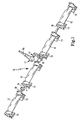
- a switching flap assembly 10 consists of a shaft 11, which is made for example of steel and are sprayed onto the switching flaps 12, for example made of plastic. These switching flaps are spaced apart, wherein between the switching flaps bearing blocks 13 are arranged made of plastic. Furthermore, an axial stop 14 is provided by means of which the shaft can be fixed axially at the installation location.
- a further functional unit 15 in the form of an articulated lever, which can be connected to a partially illustrated push rod 16 via a ball joint 17.
- a vacuum unit for example, by a vacuum unit, not shown, possible.
- Axial stop 14 and bearing blocks 13 are functional components in the context of the invention. These have bushings 18 through which the shaft 11 can be pushed. Since the bushings are closed, the functional components can be mounted only by sliding on the shaft from the end. Therefore, the sprayed-on switching flaps 12 prevent subsequent disassembly of the functional components.
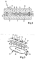
- FIG 2 a mold 19, consisting of an upper mold half 20 and a lower mold half 21 is shown. Between the two mold halves is a blank for a switching association consisting of the shaft 11 and the bearing blocks 13 (shown in simplified) inserted. Furthermore, cavities 22 can be seen in the mold, which can be filled via plastic 23 in the upper mold half 20 with plastic. This will the shaft 11 is encapsulated by the resulting switching flap, whereby the switching flap assembly is formed.
- the installation of a switching flap assembly according to the switching flap assembly 10 (here only with 3 switching flaps 12) in a suction pipe 24 is shown schematically in perspective in Figure 3.
- the joining direction is indicated by arrows 25.
- the switching flap assembly has as described bearing blocks 13 and a functional unit 15 in the form of the articulation crank.
- the entire switching assembly is installed in a receptacle 26 in the cylinder head flange 27.
- the switching flaps 12 communicate with suction channels 28 of the suction tube 24, which depart from a collecting space 29 together.
- the collecting space has a flange 30 for a throttle valve, not shown, of the intake tract for the internal combustion engine.
Landscapes
- Engineering & Computer Science (AREA)
- Combustion & Propulsion (AREA)
- Mechanical Engineering (AREA)
- General Engineering & Computer Science (AREA)
- Chemical & Material Sciences (AREA)
- Moulds For Moulding Plastics Or The Like (AREA)
- Lift Valve (AREA)
- Multiple-Way Valves (AREA)
- Injection Moulding Of Plastics Or The Like (AREA)
- Control Of Throttle Valves Provided In The Intake System Or In The Exhaust System (AREA)
- Noodles (AREA)
- Closing Of Containers (AREA)
- Auxiliary Devices For And Details Of Packaging Control (AREA)
- Orthopedics, Nursing, And Contraception (AREA)
Claims (5)
- Procédé de fabrication d'un ensemble de clapets de commutation (12) sur un arbre (11) commun, les clapets de commutation étant rapportés sur l'arbre par moulage primaire,
caractérisé par
les étapes de procédé dans l'ordre indiqué :- on fait glisser sur l'arbre au moins un composant fonctionnel (13, 14) préfabriqué qui à cet effet est muni d'un passage (18) fermé pour l'arbre,- on insère l'arbre (11) avec le composant fonctionnel (13, 14) dans un moule (19),- on réalise les clapets de commutation (12) au moyen du moule (19) de sorte qu'au moins un composant fonctionnel (13, 14) se trouve entre deux clapets de commutation (12), ceux-ci empêchant un démontage de l'élément fonctionnel,- une autre unité fonctionnel (15) en forme de levier articulé est rapportée par moulage sur l'arbre (11), le levier articulé étant disposé au centre de l'arbre (11) entre deux clapets de commutation (12). - Procédé selon la revendication 1,
caractérisé en ce qu'
au moins un composant fonctionnel (13, 14) est logé en rotation sur l'arbre et présente en particulier la forme d'un support de palier. - Procédé selon la revendication 1,
caractérisé en ce que
le composant fonctionnel (13, 14) est bloqué en rotation sur l'arbre. - Procédé selon l'une quelconque des revendications précédentes,
caractérisé en ce que
le composant fonctionnel (13, 14) est fixé axialement sur l'arbre. - Procédé selon l'une quelconque des revendications précédentes,
caractérisé en ce qu'
outre les clapets une autre unité fonctionnelle (15) est rapportée par moulage sur l'arbre.
Applications Claiming Priority (2)
| Application Number | Priority Date | Filing Date | Title |
|---|---|---|---|
| DE10131109A DE10131109A1 (de) | 2001-06-27 | 2001-06-27 | Verfahren zur Herstellung eines Schaltklappenverbandes |
| DE10131109 | 2001-06-27 |
Publications (3)
| Publication Number | Publication Date |
|---|---|
| EP1270904A2 EP1270904A2 (fr) | 2003-01-02 |
| EP1270904A3 EP1270904A3 (fr) | 2004-07-28 |
| EP1270904B1 true EP1270904B1 (fr) | 2006-11-08 |
Family
ID=7689716
Family Applications (1)
| Application Number | Title | Priority Date | Filing Date |
|---|---|---|---|
| EP02013227A Expired - Lifetime EP1270904B1 (fr) | 2001-06-27 | 2002-06-15 | Procédé de fabrication d'un ensemble de volets de commande |
Country Status (5)
| Country | Link |
|---|---|
| US (1) | US6692675B2 (fr) |
| EP (1) | EP1270904B1 (fr) |
| JP (1) | JP4368094B2 (fr) |
| AT (1) | ATE344877T1 (fr) |
| DE (2) | DE10131109A1 (fr) |
Families Citing this family (7)
| Publication number | Priority date | Publication date | Assignee | Title |
|---|---|---|---|---|
| EP1239132A1 (fr) * | 2001-03-05 | 2002-09-11 | Dsm N.V. | Corps de papillon en matière thermoplastique |
| DE102004005480B4 (de) * | 2004-02-04 | 2013-10-17 | GM Global Technology Operations LLC (n. d. Ges. d. Staates Delaware) | Schaltklappe für Saugrohr |
| DE102005029798B4 (de) * | 2005-06-27 | 2015-02-05 | Volkswagen Ag | Schaltbauteil für ein Saugrohr einer Brennkraftmaschine |
| JP2007138840A (ja) * | 2005-11-18 | 2007-06-07 | Denso Corp | 吸気装置およびその製造方法 |
| FR2960806B1 (fr) | 2010-06-04 | 2012-06-22 | Mann & Hummel Gmbh | Procede de fabrication d'un assemblage de soupapes a clapet pour un collecteur d'admission d'air et assemblage realise |
| KR101147823B1 (ko) * | 2011-01-07 | 2012-05-21 | 주식회사 이파그리드코리아 | 지오그리드와 지오그리드 제조장치 및 제조장치를 이용한 지오그리드 제조방법 |
| WO2017210169A1 (fr) * | 2016-06-01 | 2017-12-07 | Synventive Molding Solutions, Inc. | Ensemble dispositif de commande pour un système de moulage par injection |
Family Cites Families (22)
| Publication number | Priority date | Publication date | Assignee | Title |
|---|---|---|---|---|
| US3707032A (en) * | 1969-01-23 | 1972-12-26 | Weatherhead Co | Method of forming an abrasion resistant hose assembly |
| DE2063369C3 (de) * | 1970-12-23 | 1975-04-24 | Daimler-Benz Ag, 7000 Stuttgart | Lagerung einer Heizklappe im Auspuffleitungssystem einer Brennkraftmaschine |
| US4198368A (en) * | 1973-07-03 | 1980-04-15 | Imperial Chemical Industries Limited | Valve |
| US4914711A (en) * | 1981-07-23 | 1990-04-03 | Polaroid Corporation | Integrally molded bearing block assembly |
| US5049341A (en) * | 1981-07-23 | 1991-09-17 | Polaroid Corporation | Integrally molded bearing block assembly |
| US4477406A (en) * | 1981-09-22 | 1984-10-16 | Deere & Company | Method for molding elongated workpieces |
| JPS6077731U (ja) * | 1983-11-01 | 1985-05-30 | マツダ株式会社 | エンジンの吸気装置 |
| US4671746A (en) * | 1984-06-25 | 1987-06-09 | Applied Power Inc. | Base component for a fluid transfer device and method of making the component |
| US5041253A (en) * | 1987-10-01 | 1991-08-20 | Husted Royce Hill | Method of making a plastic stabilized composite camshaft |
| JPH07137179A (ja) * | 1993-07-19 | 1995-05-30 | Xerox Corp | 2つの部材を移動可能に連結した組立体を製造する方法 |
| DE4334180A1 (de) * | 1993-10-07 | 1995-04-13 | Bosch Gmbh Robert | Drosselvorrichtung |
| DE4343091A1 (de) * | 1993-12-17 | 1995-06-22 | Bosch Gmbh Robert | Drosselvorrichtung, insbesondere für eine Brennkraftmaschine, und Verfahren zum Herstellen einer Drosselvorrichtung |
| KR100222527B1 (ko) * | 1994-11-24 | 1999-10-01 | 정몽규 | 내연기관의 흡기조절장치 |
| JP3375017B2 (ja) * | 1994-12-20 | 2003-02-10 | 株式会社デンソー | スロットル弁制御装置 |
| JPH08277717A (ja) * | 1995-04-06 | 1996-10-22 | Du Pont Kk | 吸気制御バルブを備えた樹脂吸気系 |
| DE19615438A1 (de) * | 1995-07-17 | 1997-01-23 | Mann & Hummel Filter | Ventil |
| US5715782A (en) * | 1996-08-29 | 1998-02-10 | Genral Motors Corporation | Composite molded butterfly valve for an internal combustion engine |
| DE19717349A1 (de) * | 1997-03-07 | 1998-09-24 | Siemens Ag | Ansaugeinrichtung |
| JP4178642B2 (ja) * | 1998-02-04 | 2008-11-12 | 日産自動車株式会社 | 空気流量制御装置及びその製造方法 |
| DE19918777A1 (de) * | 1999-04-24 | 2000-10-26 | Mann & Hummel Filter | Schaltklappenverband aus montagegespritzten Schaltklappen oder Klappenmodulen |
| US6263917B1 (en) * | 1999-08-12 | 2001-07-24 | Delphi Technologies, Inc. | Multiple-bore throttle valve having central shaft end-play restraint |
| FR2797931B1 (fr) * | 1999-08-31 | 2001-10-05 | Mark Iv Systemes Moteurs Sa | Dispositif de regulation de l'ecoulement dans une portion de conduit ou un passage et collecteur comprenant un tel dispositif |
-
2001
- 2001-06-27 DE DE10131109A patent/DE10131109A1/de not_active Withdrawn
-
2002
- 2002-06-15 DE DE50208639T patent/DE50208639D1/de not_active Expired - Lifetime
- 2002-06-15 EP EP02013227A patent/EP1270904B1/fr not_active Expired - Lifetime
- 2002-06-15 AT AT02013227T patent/ATE344877T1/de not_active IP Right Cessation
- 2002-06-25 US US10/178,778 patent/US6692675B2/en not_active Expired - Lifetime
- 2002-06-26 JP JP2002186685A patent/JP4368094B2/ja not_active Expired - Fee Related
Also Published As
| Publication number | Publication date |
|---|---|
| EP1270904A3 (fr) | 2004-07-28 |
| EP1270904A2 (fr) | 2003-01-02 |
| JP2003039252A (ja) | 2003-02-12 |
| DE10131109A1 (de) | 2003-01-09 |
| US20030009881A1 (en) | 2003-01-16 |
| US6692675B2 (en) | 2004-02-17 |
| DE50208639D1 (de) | 2006-12-21 |
| JP4368094B2 (ja) | 2009-11-18 |
| ATE344877T1 (de) | 2006-11-15 |
Similar Documents
| Publication | Publication Date | Title |
|---|---|---|
| EP1175556B1 (fr) | Ensemble volets de commande constitue de volets de commande, moules par injection au moment du montage, ou de modules a volets | |
| EP1521893B1 (fr) | Fermeture comportant deux tiges de verrouillage, notamment pour des vehicules | |
| DE4322586A1 (de) | Betätigungsvorrichtung für eine Schiebemuffe in einem Kraftfahrzeug-Stufengetriebe | |
| EP1802877B1 (fr) | Systeme de douilles flexible | |
| EP3722641A1 (fr) | Agencement de porte satellites d'un engrenage épicycloïdal, en particulier un engrenage épicycloïdal d'un entraînement de porte latérale, ainsi que procédé de fabrication d'un tel agencement de porte satellites | |
| EP1270904B1 (fr) | Procédé de fabrication d'un ensemble de volets de commande | |
| EP0747587B1 (fr) | Dispositif pour ajuster la longueur de tuyaux d'un dispositif d'admission et procédé de fabrication | |
| EP1420938B1 (fr) | Procede de fabrication d'un boitier tubulaire de clapet d'etranglement et d'un clapet d'etranglement | |
| DE60303544T2 (de) | Herstellungsverfahren für das Rotorkomponent eines Positionsgebers eines Drehklappenventils für eine Brennkraftmaschine | |
| WO2022112525A1 (fr) | Ensemble arbre à cames coulissantes conçu pour un moteur à combustion interne, et procédé pour commuter un ensemble arbre à cames coulissantes pour un moteur à combustion interne | |
| EP1419330B1 (fr) | Tubulure de papillon des gaz pour un moteur a combustion interne | |
| DE3606073C2 (de) | Drehgelenk | |
| EP1826375B1 (fr) | Soupape de commutation et son procédé de fabrication | |
| EP1563174B1 (fr) | Procede pour produire un boitier de papillon | |
| EP1517776B1 (fr) | Procede de fabrication d'un papillon dans un corps de papillon continu par moulage par injection de matiere plastique | |
| EP0280774B1 (fr) | Entraînement de l'arbre de distribution d'un moteur à piston alternatif | |
| EP1447603A2 (fr) | Soupape à papillon et procédé pour la produire | |
| EP2064047B1 (fr) | Procede et outil d'injection pour la fabrication d' un conduit d'admission en matiere synthetique pour moteurs a combustion interne et conduit d'admission ainsi fabrique | |
| EP1991406B1 (fr) | Procede de moulage par injection pour la fabrication d'un element ayant au moins deux composants fonctionnels realises separement l'un de l'autre et deplaçables l'un par rapport a l'autre | |
| DE102007027844A1 (de) | Verfahren zur Herstellung eines Verbundbauteils und Verbundbauteil, das mit einer Handhabe zur Bewegung eines beweglichen Teils koppelbar ist | |
| DE102014013586B4 (de) | Gelenkeinheit und Verfahren zur Herstellung eines Gelenks | |
| WO1997013060A1 (fr) | Systeme d'admission pour un moteur a combustion interne a plusieurs cylindres | |
| DE4014143C2 (fr) | ||
| DE102023103004A1 (de) | Stößelstange für eine Ventilbetätigungseinrichtung einer Brennkraftmaschine und Ventilbetätigungseinrichtung mit einer solchen Stößelstange, Brennkraftmaschine und Verwendung einer Stößelstange | |
| DE102022209343A1 (de) | Schaltvorrichtung für ein Getriebe |
Legal Events
| Date | Code | Title | Description |
|---|---|---|---|
| PUAI | Public reference made under article 153(3) epc to a published international application that has entered the european phase |
Free format text: ORIGINAL CODE: 0009012 |
|
| AK | Designated contracting states |
Kind code of ref document: A2 Designated state(s): AT BE CH CY DE DK ES FI FR GB GR IE IT LI LU MC NL PT SE TR |
|
| AX | Request for extension of the european patent |
Free format text: AL;LT;LV;MK;RO;SI |
|
| RAP1 | Party data changed (applicant data changed or rights of an application transferred) |
Owner name: MANN + HUMMEL GMBH |
|
| PUAL | Search report despatched |
Free format text: ORIGINAL CODE: 0009013 |
|
| AK | Designated contracting states |
Kind code of ref document: A3 Designated state(s): AT BE CH CY DE DK ES FI FR GB GR IE IT LI LU MC NL PT SE TR |
|
| AX | Request for extension of the european patent |
Extension state: AL LT LV MK RO SI |
|
| 17P | Request for examination filed |
Effective date: 20040831 |
|
| 17Q | First examination report despatched |
Effective date: 20041117 |
|
| AKX | Designation fees paid | ||
| REG | Reference to a national code |
Ref country code: DE Ref legal event code: 8566 |
|
| RBV | Designated contracting states (corrected) |
Designated state(s): AT BE CH CY DE DK ES FI FR GB GR IE IT LI LU MC NL PT SE TR |
|
| GRAP | Despatch of communication of intention to grant a patent |
Free format text: ORIGINAL CODE: EPIDOSNIGR1 |
|
| GRAS | Grant fee paid |
Free format text: ORIGINAL CODE: EPIDOSNIGR3 |
|
| GRAA | (expected) grant |
Free format text: ORIGINAL CODE: 0009210 |
|
| AK | Designated contracting states |
Kind code of ref document: B1 Designated state(s): AT BE CH CY DE DK ES FI FR GB GR IE IT LI LU MC NL PT SE TR |
|
| PG25 | Lapsed in a contracting state [announced via postgrant information from national office to epo] |
Ref country code: FI Free format text: LAPSE BECAUSE OF FAILURE TO SUBMIT A TRANSLATION OF THE DESCRIPTION OR TO PAY THE FEE WITHIN THE PRESCRIBED TIME-LIMIT Effective date: 20061108 Ref country code: NL Free format text: LAPSE BECAUSE OF FAILURE TO SUBMIT A TRANSLATION OF THE DESCRIPTION OR TO PAY THE FEE WITHIN THE PRESCRIBED TIME-LIMIT Effective date: 20061108 Ref country code: IE Free format text: LAPSE BECAUSE OF FAILURE TO SUBMIT A TRANSLATION OF THE DESCRIPTION OR TO PAY THE FEE WITHIN THE PRESCRIBED TIME-LIMIT Effective date: 20061108 |
|
| REG | Reference to a national code |
Ref country code: GB Ref legal event code: FG4D Free format text: NOT ENGLISH |
|
| REG | Reference to a national code |
Ref country code: CH Ref legal event code: EP |
|
| REG | Reference to a national code |
Ref country code: IE Ref legal event code: FG4D Free format text: LANGUAGE OF EP DOCUMENT: GERMAN |
|
| REF | Corresponds to: |
Ref document number: 50208639 Country of ref document: DE Date of ref document: 20061221 Kind code of ref document: P |
|
| PG25 | Lapsed in a contracting state [announced via postgrant information from national office to epo] |
Ref country code: SE Free format text: LAPSE BECAUSE OF FAILURE TO SUBMIT A TRANSLATION OF THE DESCRIPTION OR TO PAY THE FEE WITHIN THE PRESCRIBED TIME-LIMIT Effective date: 20070208 Ref country code: DK Free format text: LAPSE BECAUSE OF FAILURE TO SUBMIT A TRANSLATION OF THE DESCRIPTION OR TO PAY THE FEE WITHIN THE PRESCRIBED TIME-LIMIT Effective date: 20070208 |
|
| PG25 | Lapsed in a contracting state [announced via postgrant information from national office to epo] |
Ref country code: ES Free format text: LAPSE BECAUSE OF FAILURE TO SUBMIT A TRANSLATION OF THE DESCRIPTION OR TO PAY THE FEE WITHIN THE PRESCRIBED TIME-LIMIT Effective date: 20070219 |
|
| GBT | Gb: translation of ep patent filed (gb section 77(6)(a)/1977) |
Effective date: 20070129 |
|
| PG25 | Lapsed in a contracting state [announced via postgrant information from national office to epo] |
Ref country code: PT Free format text: LAPSE BECAUSE OF FAILURE TO SUBMIT A TRANSLATION OF THE DESCRIPTION OR TO PAY THE FEE WITHIN THE PRESCRIBED TIME-LIMIT Effective date: 20070409 |
|
| NLV1 | Nl: lapsed or annulled due to failure to fulfill the requirements of art. 29p and 29m of the patents act | ||
| ET | Fr: translation filed | ||
| REG | Reference to a national code |
Ref country code: IE Ref legal event code: FD4D |
|
| PLBE | No opposition filed within time limit |
Free format text: ORIGINAL CODE: 0009261 |
|
| STAA | Information on the status of an ep patent application or granted ep patent |
Free format text: STATUS: NO OPPOSITION FILED WITHIN TIME LIMIT |
|
| 26N | No opposition filed |
Effective date: 20070809 |
|
| BERE | Be: lapsed |
Owner name: MANN + HUMMEL G.M.B.H. Effective date: 20070630 |
|
| PG25 | Lapsed in a contracting state [announced via postgrant information from national office to epo] |
Ref country code: MC Free format text: LAPSE BECAUSE OF NON-PAYMENT OF DUE FEES Effective date: 20070630 |
|
| REG | Reference to a national code |
Ref country code: CH Ref legal event code: PL |
|
| PG25 | Lapsed in a contracting state [announced via postgrant information from national office to epo] |
Ref country code: BE Free format text: LAPSE BECAUSE OF NON-PAYMENT OF DUE FEES Effective date: 20070630 |
|
| PG25 | Lapsed in a contracting state [announced via postgrant information from national office to epo] |
Ref country code: GR Free format text: LAPSE BECAUSE OF FAILURE TO SUBMIT A TRANSLATION OF THE DESCRIPTION OR TO PAY THE FEE WITHIN THE PRESCRIBED TIME-LIMIT Effective date: 20070209 Ref country code: LI Free format text: LAPSE BECAUSE OF NON-PAYMENT OF DUE FEES Effective date: 20070630 Ref country code: CH Free format text: LAPSE BECAUSE OF NON-PAYMENT OF DUE FEES Effective date: 20070630 |
|
| PG25 | Lapsed in a contracting state [announced via postgrant information from national office to epo] |
Ref country code: AT Free format text: LAPSE BECAUSE OF NON-PAYMENT OF DUE FEES Effective date: 20070615 |
|
| PG25 | Lapsed in a contracting state [announced via postgrant information from national office to epo] |
Ref country code: CY Free format text: LAPSE BECAUSE OF FAILURE TO SUBMIT A TRANSLATION OF THE DESCRIPTION OR TO PAY THE FEE WITHIN THE PRESCRIBED TIME-LIMIT Effective date: 20061108 Ref country code: LU Free format text: LAPSE BECAUSE OF NON-PAYMENT OF DUE FEES Effective date: 20070615 |
|
| PG25 | Lapsed in a contracting state [announced via postgrant information from national office to epo] |
Ref country code: TR Free format text: LAPSE BECAUSE OF FAILURE TO SUBMIT A TRANSLATION OF THE DESCRIPTION OR TO PAY THE FEE WITHIN THE PRESCRIBED TIME-LIMIT Effective date: 20061108 |
|
| PGFP | Annual fee paid to national office [announced via postgrant information from national office to epo] |
Ref country code: GB Payment date: 20120622 Year of fee payment: 11 |
|
| GBPC | Gb: european patent ceased through non-payment of renewal fee |
Effective date: 20130615 |
|
| PG25 | Lapsed in a contracting state [announced via postgrant information from national office to epo] |
Ref country code: GB Free format text: LAPSE BECAUSE OF NON-PAYMENT OF DUE FEES Effective date: 20130615 |
|
| REG | Reference to a national code |
Ref country code: FR Ref legal event code: PLFP Year of fee payment: 15 |
|
| PGFP | Annual fee paid to national office [announced via postgrant information from national office to epo] |
Ref country code: IT Payment date: 20160628 Year of fee payment: 15 |
|
| REG | Reference to a national code |
Ref country code: FR Ref legal event code: PLFP Year of fee payment: 16 |
|
| PG25 | Lapsed in a contracting state [announced via postgrant information from national office to epo] |
Ref country code: IT Free format text: LAPSE BECAUSE OF NON-PAYMENT OF DUE FEES Effective date: 20170615 |
|
| REG | Reference to a national code |
Ref country code: FR Ref legal event code: PLFP Year of fee payment: 17 |
|
| REG | Reference to a national code |
Ref country code: DE Ref legal event code: R081 Ref document number: 50208639 Country of ref document: DE Owner name: MANN+HUMMEL GMBH, DE Free format text: FORMER OWNER: MANN + HUMMEL GMBH, 71638 LUDWIGSBURG, DE |
|
| PGFP | Annual fee paid to national office [announced via postgrant information from national office to epo] |
Ref country code: DE Payment date: 20200618 Year of fee payment: 19 Ref country code: FR Payment date: 20200619 Year of fee payment: 19 |
|
| REG | Reference to a national code |
Ref country code: DE Ref legal event code: R119 Ref document number: 50208639 Country of ref document: DE |
|
| PG25 | Lapsed in a contracting state [announced via postgrant information from national office to epo] |
Ref country code: DE Free format text: LAPSE BECAUSE OF NON-PAYMENT OF DUE FEES Effective date: 20220101 |
|
| PG25 | Lapsed in a contracting state [announced via postgrant information from national office to epo] |
Ref country code: FR Free format text: LAPSE BECAUSE OF NON-PAYMENT OF DUE FEES Effective date: 20210630 |