EP1271003A2 - Verfahren und System zur Abschätzung einer Null- Geschwindigkeit - Google Patents
Verfahren und System zur Abschätzung einer Null- Geschwindigkeit Download PDFInfo
- Publication number
- EP1271003A2 EP1271003A2 EP02077068A EP02077068A EP1271003A2 EP 1271003 A2 EP1271003 A2 EP 1271003A2 EP 02077068 A EP02077068 A EP 02077068A EP 02077068 A EP02077068 A EP 02077068A EP 1271003 A2 EP1271003 A2 EP 1271003A2
- Authority
- EP
- European Patent Office
- Prior art keywords
- signal
- vehicle speed
- indicates
- status signal
- vehicle
- Prior art date
- Legal status (The legal status is an assumption and is not a legal conclusion. Google has not performed a legal analysis and makes no representation as to the accuracy of the status listed.)
- Withdrawn
Links
Images


Classifications
-
- F—MECHANICAL ENGINEERING; LIGHTING; HEATING; WEAPONS; BLASTING
- F16—ENGINEERING ELEMENTS AND UNITS; GENERAL MEASURES FOR PRODUCING AND MAINTAINING EFFECTIVE FUNCTIONING OF MACHINES OR INSTALLATIONS; THERMAL INSULATION IN GENERAL
- F16H—GEARING
- F16H59/00—Control inputs to control units of change-speed- or reversing-gearings for conveying rotary motion
- F16H59/36—Inputs being a function of speed
- F16H59/44—Inputs being a function of speed dependent on machine speed, e.g. the vehicle speed
-
- F—MECHANICAL ENGINEERING; LIGHTING; HEATING; WEAPONS; BLASTING
- F16—ENGINEERING ELEMENTS AND UNITS; GENERAL MEASURES FOR PRODUCING AND MAINTAINING EFFECTIVE FUNCTIONING OF MACHINES OR INSTALLATIONS; THERMAL INSULATION IN GENERAL
- F16H—GEARING
- F16H59/00—Control inputs to control units of change-speed- or reversing-gearings for conveying rotary motion
- F16H59/14—Inputs being a function of torque or torque demand
- F16H59/18—Inputs being a function of torque or torque demand dependent on the position of the accelerator pedal
- F16H59/22—Idle position
-
- F—MECHANICAL ENGINEERING; LIGHTING; HEATING; WEAPONS; BLASTING
- F16—ENGINEERING ELEMENTS AND UNITS; GENERAL MEASURES FOR PRODUCING AND MAINTAINING EFFECTIVE FUNCTIONING OF MACHINES OR INSTALLATIONS; THERMAL INSULATION IN GENERAL
- F16H—GEARING
- F16H59/00—Control inputs to control units of change-speed- or reversing-gearings for conveying rotary motion
- F16H59/50—Inputs being a function of the status of the machine, e.g. position of doors or safety belts
- F16H59/54—Inputs being a function of the status of the machine, e.g. position of doors or safety belts dependent on signals from the brakes, e.g. parking brakes
Definitions
- a fixed sensor is attached to or on a casing associated with the system to measure the rotational speed of an object to be monitored or providing an appropriate ratio to the desired speed.
- a fixed sensor is acceptable for most speed sensing applications, there are situations where a fixed sensor is unable to accurately measure the desired speed or the expense of the sensor is prohibitive. For example, measuring the speed at zero speed or in the near zero speed region cannot easily be accomplished with such fixed sensors. Additionally, such fixed sensors generally cannot provide an accurate measurement at zero speed or near zero speed. In many vehicle applications detecting that the vehicle is truly at zero speed is complicated by the inaccuracy of the sensors employed. Yet another problem associated with fixed sensors is sensing directional rotational speed. Such measurements usually require quadrature-decoding or similar type hardware.
- a method of determining an estimate of zero speed of a vehicle comprises obtaining or acquiring a drive train status signal, a brake signal, a parking brake signal, a vehicle speed signal, and a throttle position signal.
- the method further comprises formulating a zero speed status signal under selected conditions to in response to at least one of the abovementioned signals.
- a storage medium encoded with a machine-readable computer program code for determining an estimate of zero speed of a vehicle, the storage medium including instructions for causing controller to implement the abovementioned method.
- a computer data signal embodied in a carrier wave for determining an estimate of zero speed of a vehicle comprising code configured to cause a controller to implement the abovementioned method.
- An exemplary embodiment is described herein by way of illustration as may be applied to a vehicle and more specifically a vehicle steering system. While a preferred embodiment is shown and described, it will be appreciated by those skilled in the art that the invention is not limited to the embodiment and application described herein, but also to any vehicle where zero speed estimation or determination is desired. Moreover, while an exemplary embodiment is disclosed and illustrated with reference to Boolean logic and combinatorial logic gates, it will be appreciated that such illustration should not be construed as limiting. Those skilled in the art will appreciate that a variety of potential implementations and configurations are possible within the scope of the disclosed embodiments.
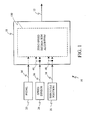
- control system 10 includes, but is not limited to, a controller 18 coupled to various sensors and interfaces for performing a variety of processes prescribed by the desired controlling functions. Also depicted are the gear selector 20, vehicle speed sensor 26, and throttle position sensor 28. In addition, the control system 10 may also include, but not be limited to, a parking brake switch 22 and a brake switch 24.
- a drive train status signal 30 indicative of a selected gear is monitored.
- a drive train status signal 30 may include five states indicative of Park, Reverse, Neutral, Drive and Low (PRNDL).
- PRNDL Park, Reverse, Neutral, Drive and Low
- the vehicle speed sensor 26 generates a vehicle speed signal 36 proportionally related to the vehicle speed. From this vehicle speed signal 36, a vehicle speed status signal 46 is generated when the vehicle speed is less than a selected threshold value.
- the vehicle speed status signal 46 may be generated by a comparator or similar means of comparing the measured vehicle speed signal 36 and a selected threshold.
- the vehicle speed status signal 46 may be a two state signal with a valid state indicating that the vehicle speed is less than the selected threshold (e.g., less than about 3 miles per hour,).
- a throttle position signal 38 provides an indication of the percentage throttle applied by an operator as measured by a throttle position sensor 28.
- a throttle position status signal 48 is generated when the throttle position is less than a selected threshold.
- the throttle position status signal 48 may be generated by a comparator or similar means of comparing the measured throttle position signal 38 and a selected threshold.
- the throttle position status signal 48 may be a two state signal with a valid state indicating that the throttle position is less than the selected threshold (e.g., about 0.0 percent).
- controller 18 may include, but not be limited to, a processor(s), computer(s), memory, storage, register(s), timing, interrupt(s), communication interfaces, and input/output signal interfaces, and the like, as well as combinations comprising at least one of the foregoing.
- controller 18 may include input signal filtering to enable accurate sampling and conversion or acquisitions of such signals from communications interfaces. Additional features of controller 18 and certain processes therein are thoroughly discussed at a later point herein.
- Controller 18 receives various input signals including, but not limited to, those identified above, to facilitate such processing and may provide one or more output signals in response.
- the controller 18 receives as input signals: the drive train status signal 30, the vehicle speed signal 36 and/or its status, and the throttle position signal 38 and/or its status.
- the zero speed estimation algorithm 100 generates a zero speed status signal 12 to facilitate other processes of controller 18 and vehicle operation.
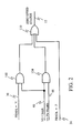
- the zero speed estimation algorithm 100 may now be described by way of reference once again to Figure 2.
- the status of the various signals is determined and then utilized in a logical combination to formulate a zero speed status signal 12.
- a valid state for the zero speed status signal 12 representing that the algorithm estimates the vehicle is at about zero speed, while an invalid state represents the converse.
- a valid, zero speed status signal 12 indicating zero speed will be generated. The first such condition occurs when the drive train status signal 30 indicates the vehicle is in the Park (P) state.
- the second condition for a valid zero speed status signal 12 is when the vehicle speed status signal 46, is valid which indicates that vehicle speed is less than a selected value; and the throttle position status signal 48 is valid, which indicates that the throttle is at about zero percent.
- a selected minimum value of three miles per hour (mph) has been utilized for the selected value of vehicle speed.
- the logical combination identified is performed at logic gate 104 providing the prescribed logical functions on the specified inputs.
- a valid zero speed status signal 12 is generated via OR logic gate 110 if one or more of the abovementioned conditions is satisfied.
- the resultants of the respective gates 102, and 108 as well as when the status of the drive train status signal 30 indicating the vehicle is in the Park (P) state are thereafter applied to a combining gate 110 providing a logical ORing of the signals, the resultant of which is the resultant zero speed status signal 12. Therefore, by the logic provided an estimation of when the vehicle is operating at zero speed is accomplished for most operation conditions.
- a parking brake signal 32 is monitored, which is representative of the status of the parking brake switch 22.
- a valid or active state of the parking brake signal 32 indicates the application of a parking brake in a vehicle.
- a brake signal 34 is also monitored, which is representative of the status of the brake switch 24.
- a valid or active state of the brake signal 34 indicates and the application of a vehicle brake.
- a process executed by controller 18 may be estimating and determining from various system measurements, parameters, and states when a vehicle is operating at zero speed.
- Controller 18 receives various input signals including, but not limited to, those identified above, to facilitate such processing and may provide one or more output signals in response.
- the controller 18 receives as input signals: a parking brake signal 32, and a brake signal 34.
- the zero speed estimation algorithm 100 generates a zero speed status signal 12 to facilitate other processes of controller 18 and vehicle operation.
- the zero speed estimation algorithm 100 may now be described by way of reference once again to Figure 4.
- the status of the various signals is determined and then utilized in a logical combination to formulate a zero speed status signal 12.
- a valid state for the zero speed status signal 12 representing that the algorithm estimates the vehicle is at about zero speed, while an invalid state represents the converse.
- a valid, zero speed status signal 12 indicating zero speed will be generated. The first such condition occurs when the drive train status signal 30 indicates the vehicle is in the Park (P) state.
- the second condition for a valid zero speed status signal 12 is when the drive train status signal 30 indicates the vehicle is not in the Park (P) state and all of the following are also true: (1) the vehicle speed status signal 46, is valid which indicates that vehicle speed is less than a selected value; (2) the throttle position status signal 48 is valid, which indicates that the throttle is at about zero percent; (3) either the brake or parking brake is set as indicated by the valid state of the brake signal 34 and parking brake signal 32 respectively. In an exemplary embodiment a selected minimum value of three miles per hour (mph) has been utilized for the selected value of vehicle speed.
- the logical combination identified is performed at logic gates 104, 106, and 108 providing the prescribed logical functions on the specified inputs.
- a valid zero speed status signal 12 is generated via OR logic gate 110 if one or more of the abovementioned conditions is satisfied.
- the resultants of the respective gates 102, and 108 as well as when the status of the drive train status signal 30 indicating the vehicle is in the Park (P) state are thereafter applied to a combining gate 110 providing a logical ORing of the signals, the resultant of which is the resultant zero speed status signal 12. Therefore, by the logic provided an estimation of when the vehicle is operating at zero speed is accomplished for most operation conditions.
- the disclosed invention can be embodied in the form of computer or controller implemented processes and apparatuses for practicing those processes.
- the present invention can also be embodied in the form of computer program code containing instructions embodied in tangible media, such as floppy diskettes, CD-ROMs, hard drives, or any other computer-readable storage medium, wherein, when the computer program code is loaded into and executed by a computer or controller, the computer becomes an apparatus for practicing the invention.
- the present invention can also be embodied in the form of computer program code, for example, whether stored in a storage medium, loaded into and/or executed by a computer or controller, or transmitted over some transmission medium, such as over electrical wiring or cabling, through fiber optics, or via electromagnetic radiation, wherein, when the computer program code is loaded into and executed by a computer, the computer becomes an apparatus for practicing the invention.
- computer program code segments configure the microprocessor to create specific logic circuits.
Landscapes
- Engineering & Computer Science (AREA)
- General Engineering & Computer Science (AREA)
- Mechanical Engineering (AREA)
- Control Of Transmission Device (AREA)
- Electric Propulsion And Braking For Vehicles (AREA)
- Indicating Or Recording The Presence, Absence, Or Direction Of Movement (AREA)
- Control Of Driving Devices And Active Controlling Of Vehicle (AREA)
- Combined Controls Of Internal Combustion Engines (AREA)
Applications Claiming Priority (2)
| Application Number | Priority Date | Filing Date | Title |
|---|---|---|---|
| US885718 | 2001-06-20 | ||
| US09/885,718 US20020198630A1 (en) | 2001-06-20 | 2001-06-20 | Method and system for zero speed estimation |
Publications (1)
| Publication Number | Publication Date |
|---|---|
| EP1271003A2 true EP1271003A2 (de) | 2003-01-02 |
Family
ID=25387554
Family Applications (1)
| Application Number | Title | Priority Date | Filing Date |
|---|---|---|---|
| EP02077068A Withdrawn EP1271003A2 (de) | 2001-06-20 | 2002-05-27 | Verfahren und System zur Abschätzung einer Null- Geschwindigkeit |
Country Status (3)
| Country | Link |
|---|---|
| US (1) | US20020198630A1 (de) |
| EP (1) | EP1271003A2 (de) |
| JP (1) | JP2003107101A (de) |
Families Citing this family (2)
| Publication number | Priority date | Publication date | Assignee | Title |
|---|---|---|---|---|
| JP5088809B2 (ja) * | 2006-04-03 | 2012-12-05 | 本田技研工業株式会社 | シーケンシャル自動変速機 |
| US9020659B2 (en) * | 2012-06-15 | 2015-04-28 | Ford Global Technologies, Llc | Dynamometer vehicle operating mode control |
-
2001
- 2001-06-20 US US09/885,718 patent/US20020198630A1/en not_active Abandoned
-
2002
- 2002-05-27 JP JP2002151901A patent/JP2003107101A/ja active Pending
- 2002-05-27 EP EP02077068A patent/EP1271003A2/de not_active Withdrawn
Also Published As
| Publication number | Publication date |
|---|---|
| US20020198630A1 (en) | 2002-12-26 |
| JP2003107101A (ja) | 2003-04-09 |
Similar Documents
| Publication | Publication Date | Title |
|---|---|---|
| US7096116B2 (en) | Vehicle behavior detector, in-vehicle processing system, detection information calibrator, and in-vehicle processor | |
| JP4037131B2 (ja) | 挙動計測装置 | |
| JP5460148B2 (ja) | 測位装置及びプログラム | |
| US20020128764A1 (en) | Method and device for estimating a transverse acceleration at an axle of a semitrailer or a trailer of a vehicle combination | |
| US20110301779A1 (en) | Vehicle relative position estimation apparatus and vehicle relative position estimation method | |
| JP2007516409A (ja) | 自動車の全質量の推定方法及び装置 | |
| CN112046492B (zh) | 一种带有方向的车辆车速计算方法、装置、设备及介质 | |
| JP2007127624A (ja) | 車両速度の符号を認識し、道路傾斜を評価する方法およびシステム | |
| US10337606B2 (en) | Shift control device for automatic transmission | |
| CN111103877A (zh) | 移动机器人打滑预警方法、存储介质以及移动机器人 | |
| CA2363917C (en) | Method and apparatus for estimating tire air pressure | |
| EP1271003A2 (de) | Verfahren und System zur Abschätzung einer Null- Geschwindigkeit | |
| JP5601188B2 (ja) | 測位精度判定装置 | |
| JP5222814B2 (ja) | 測位方法および装置 | |
| JP2009119958A (ja) | 車両状態推定装置 | |
| JP4671435B2 (ja) | 自動車のステアリングホイールの角度位置推定方法及び装置 | |
| JP7770353B2 (ja) | 車速推定装置、位置算出装置及びプログラム | |
| EP2169406B1 (de) | Verfahren zur Ermittlung der Geschwindigkeit eines elektrischen Motors | |
| JP4449201B2 (ja) | 操舵トルク推定装置および操舵トルク推定方法並びに操舵装置 | |
| CN112319612A (zh) | 一种基于视觉传感器的汽车转向自由行程测量方法 | |
| JP2000074931A (ja) | 車速検出装置 | |
| JP3169213B2 (ja) | 移動速度検出方法及び装置、車両のすべり角検出装置 | |
| JPH09311036A (ja) | 車両用操舵角検出装置 | |
| CN112319485A (zh) | 一种基多模态数据分析驾驶员驾驶操作的方法及系统 | |
| JPH04244463A (ja) | 自動車の車体速度の推定方法 |
Legal Events
| Date | Code | Title | Description |
|---|---|---|---|
| PUAI | Public reference made under article 153(3) epc to a published international application that has entered the european phase |
Free format text: ORIGINAL CODE: 0009012 |
|
| AK | Designated contracting states |
Kind code of ref document: A2 Designated state(s): AT BE CH CY DE DK ES FI FR GB GR IE IT LI LU MC NL PT SE TR |
|
| AX | Request for extension of the european patent |
Free format text: AL;LT;LV;MK;RO;SI |
|
| STAA | Information on the status of an ep patent application or granted ep patent |
Free format text: STATUS: THE APPLICATION IS DEEMED TO BE WITHDRAWN |
|
| 18D | Application deemed to be withdrawn |
Effective date: 20041201 |