EP1271707A1 - Kabelbaumverbinder eines elektrischen Geräts - Google Patents
Kabelbaumverbinder eines elektrischen Geräts Download PDFInfo
- Publication number
- EP1271707A1 EP1271707A1 EP01250282A EP01250282A EP1271707A1 EP 1271707 A1 EP1271707 A1 EP 1271707A1 EP 01250282 A EP01250282 A EP 01250282A EP 01250282 A EP01250282 A EP 01250282A EP 1271707 A1 EP1271707 A1 EP 1271707A1
- Authority
- EP
- European Patent Office
- Prior art keywords
- interaction
- locking means
- release
- control section
- insertion control
- Prior art date
- Legal status (The legal status is an assumption and is not a legal conclusion. Google has not performed a legal analysis and makes no representation as to the accuracy of the status listed.)
- Withdrawn
Links
- 238000003780 insertion Methods 0.000 claims abstract description 99
- 230000037431 insertion Effects 0.000 claims abstract description 99
- 230000003993 interaction Effects 0.000 claims abstract description 73
- 230000007246 mechanism Effects 0.000 claims abstract description 62
- 230000008878 coupling Effects 0.000 claims abstract description 59
- 238000010168 coupling process Methods 0.000 claims abstract description 59
- 238000005859 coupling reaction Methods 0.000 claims abstract description 59
- 238000000926 separation method Methods 0.000 description 10
- 230000008901 benefit Effects 0.000 description 5
- 230000001419 dependent effect Effects 0.000 description 2
- 239000013013 elastic material Substances 0.000 description 2
- 239000000446 fuel Substances 0.000 description 2
- 238000012423 maintenance Methods 0.000 description 2
- 239000000463 material Substances 0.000 description 2
- 206010044565 Tremor Diseases 0.000 description 1
- 238000005452 bending Methods 0.000 description 1
- 230000003197 catalytic effect Effects 0.000 description 1
- 230000007547 defect Effects 0.000 description 1
- 230000006698 induction Effects 0.000 description 1
- 238000012986 modification Methods 0.000 description 1
- 230000004048 modification Effects 0.000 description 1
- 230000035515 penetration Effects 0.000 description 1
- 230000002093 peripheral effect Effects 0.000 description 1
- 230000001012 protector Effects 0.000 description 1
- 238000011084 recovery Methods 0.000 description 1
- 239000007787 solid Substances 0.000 description 1
Images


Classifications
-
- H—ELECTRICITY
- H01—ELECTRIC ELEMENTS
- H01R—ELECTRICALLY-CONDUCTIVE CONNECTIONS; STRUCTURAL ASSOCIATIONS OF A PLURALITY OF MUTUALLY-INSULATED ELECTRICAL CONNECTING ELEMENTS; COUPLING DEVICES; CURRENT COLLECTORS
- H01R13/00—Details of coupling devices of the kinds covered by groups H01R12/70 or H01R24/00 - H01R33/00
- H01R13/62—Means for facilitating engagement or disengagement of coupling parts or for holding them in engagement
-
- H—ELECTRICITY
- H01—ELECTRIC ELEMENTS
- H01R—ELECTRICALLY-CONDUCTIVE CONNECTIONS; STRUCTURAL ASSOCIATIONS OF A PLURALITY OF MUTUALLY-INSULATED ELECTRICAL CONNECTING ELEMENTS; COUPLING DEVICES; CURRENT COLLECTORS
- H01R13/00—Details of coupling devices of the kinds covered by groups H01R12/70 or H01R24/00 - H01R33/00
- H01R13/64—Means for preventing incorrect coupling
- H01R13/641—Means for preventing incorrect coupling by indicating incorrect coupling; by indicating correct or full engagement
-
- H—ELECTRICITY
- H01—ELECTRIC ELEMENTS
- H01R—ELECTRICALLY-CONDUCTIVE CONNECTIONS; STRUCTURAL ASSOCIATIONS OF A PLURALITY OF MUTUALLY-INSULATED ELECTRICAL CONNECTING ELEMENTS; COUPLING DEVICES; CURRENT COLLECTORS
- H01R13/00—Details of coupling devices of the kinds covered by groups H01R12/70 or H01R24/00 - H01R33/00
- H01R13/62—Means for facilitating engagement or disengagement of coupling parts or for holding them in engagement
- H01R13/639—Additional means for holding or locking coupling parts together, after engagement, e.g. separate keylock, retainer strap
-
- H—ELECTRICITY
- H01—ELECTRIC ELEMENTS
- H01R—ELECTRICALLY-CONDUCTIVE CONNECTIONS; STRUCTURAL ASSOCIATIONS OF A PLURALITY OF MUTUALLY-INSULATED ELECTRICAL CONNECTING ELEMENTS; COUPLING DEVICES; CURRENT COLLECTORS
- H01R13/00—Details of coupling devices of the kinds covered by groups H01R12/70 or H01R24/00 - H01R33/00
- H01R13/62—Means for facilitating engagement or disengagement of coupling parts or for holding them in engagement
- H01R13/627—Snap or like fastening
- H01R13/6271—Latching means integral with the housing
- H01R13/6272—Latching means integral with the housing comprising a single latching arm
Definitions
- the present invention relates to a wire-harness connector of an electric apparatus, and more particularly, to a wire-harness connector of an electric apparatus for connecting an electric apparatus in a place having severe vibration, such as a car engine, which can ensure a basic coupling between the electric apparatus and a connector body and ascertain the coupled condition with ease by arranging control means to be interlocked between locking means of the connector.
- a control apparatus for controlling a power source and a wiring of an electric apparatus are connected to each other through a connector.
- a wiring in a place having severe vibration such as an engine room on which an ignition apparatus is installed, requires a wire-harness and a battery apparatus to be connected to each other.
- the ignition apparatus boosts a voltage in a power supplying part 1 through an ignition coil part 2 and supplies the boosted voltage to a spike plug 3, as shown in FIG.1.
- an ignition timing is currently controlled by a control unit 4, whereby the ignition apparatus is controlled in an electronic manner to maintain an optimum ignition condition through advance and lag of the ignition timing.
- the power supply part 1, the ignition coil part 2 and the spike plug 3 are interconnected by means of the control unit 4.
- the connector is installed on the wire-harness, which is a power supplying line, and the ignition coil part 2, which is the electric apparatus.
- the connector requires connection ensuring means.
- the conventional connector is provided with first, second, and third, or multistage locking means for the purpose of ensuring a coupling between a terminal 5 of the electric apparatus (ignition coil part) 2 and a crimp style terminal 7 arranged on a front end of the wire-harness 6.
- the terminal 5 of the electric apparatus forms a mail part and the crimp style terminal 7 forms a female part.
- the connector ensures the mail-female terminal coupling.
- the connector is also divided into a mail part and a female part.
- a coupling body forming the mail part is formed on the electric apparatus, and a connector body 9 acts as an external cover forming the female part.
- the first locking means for ensuring the coupling between the terminals of the connector couples the connector body as the external cover and an inner cover to maintain the coupling between the terminal and the crimp style terminal, in a manner that a hook protrusion 10 is formed on an outer peripheral surface of the coupling body 8, and a hook hole 11 being engaged with the hook protrusion 10 is formed on the connector body 9.
- the hook protrusion 10 and the hook hole 11 have a front end, which is a slant surface.
- the slant surfaces are facing each other to induce the coupling between them.
- the hook hole 11 is integrally formed on a release lever 12 for releasing the hook coupling.
- the second locking means allows the crimp style terminal 7 to be fixed to the connector body 9.
- 6A fixing mechanism 13 interlocked with a separate fixing mechanism (not shown) is inserted.
- a cap 14 is mounted on a rear part of the crimp style terminal 7 to prevent foreign material penetration into the connector body 9 and fix the wire-harness 6.
- Unexplained reference numerals 15 and 15' are protectors for preventing an electric leakage.
- the hook hole 11 is integrally formed on the release lever 12 for a user to release the engagement between the hook protrusion 10 and the hook hole 11.
- the hook hole 11 and the release lever 12 are formed on both ends about a retaining wall, such that if the release lever 12 is pressed, the hook hole 11 is raised up due to deformation of an elastic material, thereby releasing the engagement between the hook hole 11 and the hook protrusion 10.
- the release lever 12 is the release means of the hook coupling of the first locking means as stated above. Accordingly, in the event that there occurs a wrong operation, for example, a unskilled person, not a maintenance man, releases and shakes the release lever 12 of the connector, or the coupling is under a possibility of being released due to an external force including vibration, a release preventing mechanism 16 which is coupling ensuring means of the connector as third locking means is arranged in order to prevent unintentional release of the coupling.
- the release preventing mechanism 16 is inserted between the release lever 12 and the connector body 9 to support the release lever 12, so that in the case of unintentional operation of the release lever 12, the hook coupling of the first locking means can be prevented from being released when the release lever 12 is pressed.
- the release preventing mechanism 16 includes a body 19 for being interacted with the retaining wall 18 which surrounds an outside of the release lever 12 of the connector body 9, and a guide jaw 21 being formed on the body 19 for being inserted into the connector body 9 along a guide groove 20 of a border part between the connector body 9 and the retaining wall 18.
- a retaining jaw 22 is formed on one side of the body 19 to support the release lever 12 in a direction in which the retaining jaw is inserted into the connector body 9.
- Latch jaws 23 and 24 are formed on the retaining jaw 22 and a front side of the retaining jaw 22 to prevent a separation of the release preventing mechanism.
- a latch jaw 25, which is engaged with the latch jaws 23 and 24, is formed on an inside of the retaining wall 18.
- the release preventing mechanism 16 is positioned in a space between the release lever 12 and the connector body 9 and then is pressed in the direction of insertion, the retaining jaw 22 is inserted according to the guide of the guide jaw 21 and positioned on a lower part of the release lever 12.
- the insertion of the release preventing mechanism 16 is released in a manner that if the body 19 is backwardly drawn, the interaction of the retaining jaw 22 and the release lever 12 is released.
- the release preventing mechanism 16 is prevented from being completely separated from the connector body 19 and missed when the insertion is released.
- the electric apparatus which is installed in a place having severe vibration, is provided with the connector for connecting the electric apparatus with the wire-harness and the locking means for ensuring the coupled condition.
- the conventional electric apparatus has a disadvantage that the coupling of the connector cannot be reliably ensured by using just the locking means.
- first, second and third locking means namely the multistage locking means are arranged on the connector as above, the locking means are operated in an independent manner and are not under a so-called interlock relation wherein the locking means ascertain other locking means' coupled condition.
- first and third locking means are interlocked since the third locking means prevents the release of the coupling of the first locking means.
- the interlocked relation exists only when the coupling is released.
- the coupling of the first locking means does not affect on the insertion of the release preventing mechanism, or the third locking means, but just obstructs the release lever 12 included in the first locking means from being pressed.
- the coupled condition of the first locking means is ascertained just depending on the user's skill.
- the coupling of the connector depends only on the user's skill, and the maintenance is also dependent on the skill of the management man. Therefore, if an unskilled person couples the connector or manages the coupling, the result may be serious.
- the coupled condition of the connector is ascertained in a manner that the hook is clicked, the deformation of the hook material and impact due to recovery are sensed with the user's hands.
- This ascertainment is generally carried out in work places, and still more in the narrow engine room in which a plurality of components are arranged.
- the coupled condition of the connector is difficult to be ascertained by hearing the click sound, since the assembly lines of factories or service stations are so nosy for the user to hear the click because of the noise in the work places.
- the coupled condition of the connector is difficult to be ascertained by sensing it with the user's gloved hands during work.
- the present invention is directed to a wire-harness connector of an electric apparatus that substantially obviates one or more problems due to limitations and disadvantages of the related art.
- An object of the present invention is to provide a wire-harness connector of an electric apparatus, which can easily ascertain a coupled condition of first locking means and ensure a coupling completed condition of the connector by inserting third locking means only when the coupling of the first locking means is completed.
- a wire-harness connector of an electric apparatus includes insertion control means being positioned between first locking means and third locking means for permitting the third locking means, in other words, a pressure preventing mechanism to be inserted only when a coupling of the first locking means is completed, wherein the insertion control means includes an insertion control section being formed on the release preventing mechanism for obstructing a release preventing mechanism from being completely inserted by being interacted with an inside of a front end of a hook hole; an interaction jaw being formed on a retaining jaw of the release preventing mechanism for helping the insertion control section to obstruct the insertion by being backwardly protruded when the inserting control section and the hook hole are interacted and being interacted with a release lever; and an interaction release protrusion for releasing the interaction between the insertion control section and the hook hole by forcing the insertion control section to be bent when the hook protrusion is coupled with the hook hole.
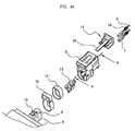
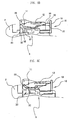
- FIG.4 illustrates an exploded cross view of a connector according to the present invention
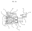
- FIG.5 illustrates a sectional view for explaining a state where the connector is coupled according to the present invention.
- insertion control means permits third locking means, namely a release preventing mechanism 16 to be inserted.
- the present invention is related to a connector of the electric apparatus, whose coupling is carried out through the first locking means and the third locking means.
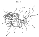
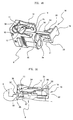
- an insertion control section 30 is integrally formed on a body 19 of the release preventing mechanism and has a length sufficient to obstruct the release preventing mechanism 16 from being completely inserted, so as to be interacted with an end part within a front side of a hook hole 11.
- An interaction jaw 31 including a guide surface 39 is formed on the release preventing mechanism 16 to help the insertion control section 30 to obstruct the insertion by being protruded on the retaining jaw 22 to be interacted with a rear end part of a release lever 12 when the insertion control section 30 is interacted with the end part within the hook hole 11.
- a hook protrusion of the first locking means which is hook-coupled with the hook hole 11 becomes an interaction release protrusion 33, which includes an interaction release guiding surface 32 for releasing the interaction between the insertion control section 30 and the hook hole 11 by forcing the insertion control section 30 to be bent.
- the insertion control section 30, which obstructs the complete insertion is as long as a length adaptable to maintain the separation in the conventional art, which were previously described.
- the separation was determined by arrangement of latch jaws 23 and 24, which are formed on a side part of the release preventing mechanism 16.
- the insertion control section is as long as the separation from the body 19 of the release preventing mechanism plus extension from the end of the separation up to the end part within the front side of the hook hole 11.
- the interaction jaw 31 is formed to help the insertion control section 30 to obstruct the release preventing mechanism 16 from being inserted.
- the interaction jaw 31 helps the interaction of the insertion control section 30 by being interacted with a front end of the release lever 12.
- the interaction jaw 31 more obstructs the insertion of the release preventing mechanism 16 under a state that the hook coupling of the first locking means is not completed and there exists a serration between the hooks.
- the lower end part of the release lever 12 is positioned lower than the guide surface 39 of the interaction jaw 31, and a large portion of a surface of the end part of the release lever 12 is interacted with the interaction jaw 31 and the retaining jaw 22, making the insertion of the release preventing mechanism 16 more difficult.
- the interaction jaw serves to prevent the insertion control section from being forcibly deformed by virtue of an elastic force resistant to the deformation of the hooks, when the user presses the release preventing mechanism to couple the connector.
- the release lever is positioned at a lower part of the interaction jaw, and thus reliably enacted with the interaction jaw.
- the interaction jaw serves to help the long type insertion control section 30 to prevent the insertion control section 30 from being forcibly bent.
- the hook hole 11 of the first locking means and the hook protrusion namely the interaction release protrusion 33 are included in the insertion control means together with the insertion control section 30, the hook hole for controlling the insertion has a limit in taking its shape.
- the end part within the front side of the hook hole 11 should be formed in a direction perpendicular to a direction of insertion of the insertion control section 30 in order to obstruct the release preventing mechanism 16 from being inserted by being interacted with the insertion control section 30.
- the insertion control section 30 is induced bent by the interaction release protrusion 33.
- the insertion control section 30 is formed of an elastic material. If a surface, which is interacted with the insertion control section 30, is set to be slant, the obstruction of the insertion of the release preventing mechanism 16 is not achievable due to the induction of the bending when the insertion control section 30 is inserted.
- the interaction surface 35 forms a surface perpendicular to the direction of the insertion of the insertion control section 30 at a position where the insertion control section 30 is inserted and interacted when the interaction release protrusion 33 is not coupled in the end part within the front side of the hook hole 11, whereby the interaction surface 35 is interacted with an interaction surface 34 of the insertion control section 30.
- the interaction surface 34 corresponding to the interaction surface 35 of the hook hole 11 is also formed in a direction perpendicular to the direction of insertion of the insertion control section 30.
- a guide surface 37 faces the interaction release guiding surface 32, so as to induce the insertion control section 30 to be bent by being extended from the interaction surface 34 and contacting with the interaction release guiding surface 32.
- the direction of insertion of the insertion control section 30 was determined by an existing retaining wall 18 and a guide jaw 21 into a straight line.
- a compressing protrusion 38 is formed on the interaction jaw 31 to maintain the insertion completed condition of the release preventing mechanism 16 by virtue of the elastic attachment of the release lever 12 when the release preventing mechanism 16 is completely inserted, and apply an elastic force to the hook coupling.
- the interaction jaw 31 acts as auxiliary means for helping the insertion obstruction of the release preventing mechanism 16 and as separation preventing means for certainly maintaining the inserted condition of the release preventing mechanism 16 through the compressing protrusion 38 as well as elastic retaining means for more ensuring the hook coupling of the first locking means.
- release lever 12 elastically attaches the compressing protrusion 38. Accordingly, since the inserted condition of the release preventing mechanism 16 is reliably maintained, the elastic attachment of the release lever 12 prevents the separation of the release preventing mechanism 16 although the connector body 9 trembles by vibration of an engine or the likes.
- the interaction jaw 31 which is a border extended from the retaining jaw 22, helps the insertion obstruction of the release preventing mechanism 16 by being interacted with the release lever 12 when the first locking means is not coupled.
- the compressing protrusion extended on the interaction jaw 31 prevents the separation of the release preventing mechanism 16 and further firmly supports the hook coupling in the elastic manner by compressing the release lever 12 if the coupling of the first locking means is completed and the release preventing mechanism is inserted into a lower part of the release lever 12.
- the hook coupling of the first locking means is a precondition for the insertion of the connector body 9 of the release preventing mechanism 16 which is the third locking means.
- the third locking means is not coupled.
- the connector is a unit product or the coupling is not completed, although the third locking means, in other words, the release preventing mechanism 16 is inserted into the connector body 9, the third locking means is not completely inserted since it is back spaced by a predetermined separation.
- the release preventing mechanism 16 is under the condition that it is not completely inserted into the connector body, maintaining the predetermined separation.
- the interaction release protrusion 33 is inserted into the hook hole 11, such that the interaction release guiding surface 32 raises the insertion control section 30, resulting in the release of the interaction.
- the release is easily performed at a point of inserting the interaction release protrusion 33. Thereafter, if the release preventing mechanism 16 is pressingly inserted, the insertion control section 30 is moved along the interaction release guiding surface 32 and the guide surface 36 of the hook hole 11.
- the release preventing mechanism 16 is not completely coupled and maintains the separated condition.
- the separated condition can be ascertained with naked eyes.
- the coupled condition is also ascertained regardless of the skill.
- the third locking means, or the release preventing mechanism 16 is not completely inserted if the locking of the first locking means is not completed in the assembly line of the connector and the electric apparatus, the user can ascertain whether the connector is coupled, and the ascertainment is not related to the user's skill.
- the coupled condition of the first locking means can be ascertained by ascertaining the insertion of the release preventing mechanism 16, the ascertainment of the connector is easily achieved and the coupling is further ensured by virtue of the elastic attachment of the release lever 12 through the compressing protrusion 38 and the elastic support of the first locking means.
- the present invention has an advantage of preventing a wrong coupling of the first locking means for coupling the terminal of the electric apparatus with the wire-harness, which is the power supply line, since the insertion control means permits the ascertainment of the coupled condition of the first locking means to be conducted with ease and ensure the coupled condition by performing the insertion completion of the third locking means only when the coupling of the first locking means is completed
- the present invention has another advantage of preventing the release preventing mechanism from being separated with the aid of the compressing protrusion, which is included in the insertion control means, as well as more firmly ensuring the hook coupling of the latch jaw.
Landscapes
- Details Of Connecting Devices For Male And Female Coupling (AREA)
Applications Claiming Priority (2)
| Application Number | Priority Date | Filing Date | Title |
|---|---|---|---|
| KR10-2001-0036571A KR100419728B1 (ko) | 2001-06-26 | 2001-06-26 | 전기장치의 커넥터 |
| KR2001036571 | 2001-06-26 |
Publications (1)
| Publication Number | Publication Date |
|---|---|
| EP1271707A1 true EP1271707A1 (de) | 2003-01-02 |
Family
ID=19711338
Family Applications (1)
| Application Number | Title | Priority Date | Filing Date |
|---|---|---|---|
| EP01250282A Withdrawn EP1271707A1 (de) | 2001-06-26 | 2001-07-26 | Kabelbaumverbinder eines elektrischen Geräts |
Country Status (5)
| Country | Link |
|---|---|
| US (1) | US20020197902A1 (de) |
| EP (1) | EP1271707A1 (de) |
| JP (1) | JP2003017188A (de) |
| KR (1) | KR100419728B1 (de) |
| CN (1) | CN1393963A (de) |
Families Citing this family (9)
| Publication number | Priority date | Publication date | Assignee | Title |
|---|---|---|---|---|
| KR100427051B1 (ko) * | 2002-05-07 | 2004-04-13 | 타이코에이엠피 주식회사 | 커넥터의 단자 이중 록킹구조 |
| JP2007177841A (ja) * | 2005-12-27 | 2007-07-12 | Kokusan Denki Co Ltd | コントロールユニット |
| KR100796028B1 (ko) * | 2006-07-28 | 2008-01-21 | 한국단자공업 주식회사 | 커넥터 록킹구조 |
| KR100912950B1 (ko) * | 2007-06-05 | 2009-08-20 | 한국단자공업 주식회사 | 커넥터하우징 |
| KR100918136B1 (ko) * | 2007-11-07 | 2009-09-17 | 엘에스전선 주식회사 | 커넥터 결합 고정장치 및 커넥터 결합 고정장치의 고정부재 |
| KR101329249B1 (ko) | 2007-12-31 | 2013-11-13 | 한국단자공업 주식회사 | 커넥터 어셈블리 |
| KR100988786B1 (ko) * | 2008-03-31 | 2010-10-20 | 한국단자공업 주식회사 | 커넥터 어셈블리 |
| US9564704B2 (en) * | 2013-06-07 | 2017-02-07 | FCI Asia Pte. Ltd. | Connector assembly |
| US10038278B2 (en) | 2016-03-17 | 2018-07-31 | Te Connectivity Corporation | Electrical connector having a connector position assurance element |
Citations (4)
| Publication number | Priority date | Publication date | Assignee | Title |
|---|---|---|---|---|
| US4370013A (en) * | 1979-09-05 | 1983-01-25 | Honda Giken Kogyo Kabushiki Kaisha | Connector device for electric circuit |
| US4938710A (en) * | 1987-12-15 | 1990-07-03 | Honda Giken Kogyo Kabushiki Kaisha | Connector apparatus |
| EP0655807A2 (de) * | 1993-11-30 | 1995-05-31 | The Whitaker Corporation | Vorrichtung zur Lagesicherung eines Verbinders |
| US5681178A (en) * | 1995-06-27 | 1997-10-28 | The Whitaker Corporation | Electrical connector with connector position assurance device |
Family Cites Families (5)
| Publication number | Priority date | Publication date | Assignee | Title |
|---|---|---|---|---|
| JPH01135674A (ja) * | 1987-11-24 | 1989-05-29 | Hitachi Ltd | プリンタの印字制御方式 |
| JP2537302B2 (ja) * | 1990-03-01 | 1996-09-25 | 矢崎総業株式会社 | 電気コネクタのロック確認装置 |
| JPH07114135B2 (ja) * | 1990-03-28 | 1995-12-06 | 矢崎総業株式会社 | 電気コネクタのロック検知機構 |
| JPH0433283A (ja) * | 1990-05-29 | 1992-02-04 | Mitsubishi Electric Corp | ソケット |
| US5775930A (en) * | 1996-12-13 | 1998-07-07 | General Motors Corporation | Electrical connector with locking connector position assurance member |
-
2001
- 2001-06-26 KR KR10-2001-0036571A patent/KR100419728B1/ko not_active Expired - Fee Related
- 2001-07-26 EP EP01250282A patent/EP1271707A1/de not_active Withdrawn
- 2001-08-03 CN CN01123922A patent/CN1393963A/zh active Pending
- 2001-08-07 US US09/923,740 patent/US20020197902A1/en not_active Abandoned
- 2001-08-15 JP JP2001246648A patent/JP2003017188A/ja active Pending
Patent Citations (4)
| Publication number | Priority date | Publication date | Assignee | Title |
|---|---|---|---|---|
| US4370013A (en) * | 1979-09-05 | 1983-01-25 | Honda Giken Kogyo Kabushiki Kaisha | Connector device for electric circuit |
| US4938710A (en) * | 1987-12-15 | 1990-07-03 | Honda Giken Kogyo Kabushiki Kaisha | Connector apparatus |
| EP0655807A2 (de) * | 1993-11-30 | 1995-05-31 | The Whitaker Corporation | Vorrichtung zur Lagesicherung eines Verbinders |
| US5681178A (en) * | 1995-06-27 | 1997-10-28 | The Whitaker Corporation | Electrical connector with connector position assurance device |
Also Published As
| Publication number | Publication date |
|---|---|
| US20020197902A1 (en) | 2002-12-26 |
| JP2003017188A (ja) | 2003-01-17 |
| KR20030000542A (ko) | 2003-01-06 |
| KR100419728B1 (ko) | 2004-02-21 |
| CN1393963A (zh) | 2003-01-29 |
Similar Documents
| Publication | Publication Date | Title |
|---|---|---|
| US6527573B2 (en) | Slide contact electrical connector | |
| JP3324087B2 (ja) | コネクタ組立体およびその取付方法 | |
| EP2445059B1 (de) | Steckerabdeckung, Stecker und Montageverfahren dafür | |
| EP1271707A1 (de) | Kabelbaumverbinder eines elektrischen Geräts | |
| KR102426325B1 (ko) | 케이블 변형 완화부 | |
| JPH08321343A (ja) | 雌型端子金具 | |
| EP0321169A2 (de) | Elektrischer Verbinder, der die Verhinderung unvollständiger Kupplung ermöglicht | |
| JPH113739A (ja) | コネクタ用端子 | |
| WO2017217208A9 (ja) | コネクタ | |
| JP4787107B2 (ja) | コネクタユニット | |
| US7172459B2 (en) | Electrical connector housing, electrical connector, and connector assembly | |
| US5785560A (en) | Ignition cable connection terminal | |
| EP1089378A1 (de) | Elektrisches Teil für Automobile, Einheit für den Automobilinnenraum und Montagevorgang | |
| JPH10321281A (ja) | コネクタ | |
| JP2002093518A (ja) | コネクタ根元の電線保護構造 | |
| KR101482793B1 (ko) | 커넥터 | |
| US6503094B1 (en) | Connector supporting structure and coupling structure | |
| JPH11250970A (ja) | コネクタ構造 | |
| JP2007227249A (ja) | コネクタ | |
| JPH08179163A (ja) | 光コネクタ | |
| KR20080096908A (ko) | 내진동 커넥터 | |
| JPH0648183U (ja) | コネクタ構造 | |
| JP2007280863A (ja) | 端子カバー及び端子カバー装着方法 | |
| JP2005108498A (ja) | コネクタの半嵌合検知構造 | |
| JP2001148263A (ja) | コネクタ |
Legal Events
| Date | Code | Title | Description |
|---|---|---|---|
| PUAI | Public reference made under article 153(3) epc to a published international application that has entered the european phase |
Free format text: ORIGINAL CODE: 0009012 |
|
| 17P | Request for examination filed |
Effective date: 20020430 |
|
| AK | Designated contracting states |
Kind code of ref document: A1 Designated state(s): AT BE CH CY DE DK ES FI FR GB GR IE IT LI LU MC NL PT SE TR |
|
| AX | Request for extension of the european patent |
Free format text: AL;LT;LV;MK;RO;SI |
|
| AKX | Designation fees paid |
Designated state(s): DE FR GB |
|
| STAA | Information on the status of an ep patent application or granted ep patent |
Free format text: STATUS: THE APPLICATION IS DEEMED TO BE WITHDRAWN |
|
| 18D | Application deemed to be withdrawn |
Effective date: 20050201 |