EP1271709A2 - Arrangement de Connecteur électrique avec système de verrouillage - Google Patents
Arrangement de Connecteur électrique avec système de verrouillage Download PDFInfo
- Publication number
- EP1271709A2 EP1271709A2 EP02291488A EP02291488A EP1271709A2 EP 1271709 A2 EP1271709 A2 EP 1271709A2 EP 02291488 A EP02291488 A EP 02291488A EP 02291488 A EP02291488 A EP 02291488A EP 1271709 A2 EP1271709 A2 EP 1271709A2
- Authority
- EP
- European Patent Office
- Prior art keywords
- short
- plug
- electrical connector
- socket
- circuit
- Prior art date
- Legal status (The legal status is an assumption and is not a legal conclusion. Google has not performed a legal analysis and makes no representation as to the accuracy of the status listed.)
- Granted
Links
Images






Classifications
-
- H—ELECTRICITY
- H01—ELECTRIC ELEMENTS
- H01R—ELECTRICALLY-CONDUCTIVE CONNECTIONS; STRUCTURAL ASSOCIATIONS OF A PLURALITY OF MUTUALLY-INSULATED ELECTRICAL CONNECTING ELEMENTS; COUPLING DEVICES; CURRENT COLLECTORS
- H01R13/00—Details of coupling devices of the kinds covered by groups H01R12/70 or H01R24/00 - H01R33/00
- H01R13/66—Structural association with built-in electrical component
- H01R13/70—Structural association with built-in electrical component with built-in switch
- H01R13/703—Structural association with built-in electrical component with built-in switch operated by engagement or disengagement of coupling parts, e.g. dual-continuity coupling part
-
- H—ELECTRICITY
- H01—ELECTRIC ELEMENTS
- H01R—ELECTRICALLY-CONDUCTIVE CONNECTIONS; STRUCTURAL ASSOCIATIONS OF A PLURALITY OF MUTUALLY-INSULATED ELECTRICAL CONNECTING ELEMENTS; COUPLING DEVICES; CURRENT COLLECTORS
- H01R13/00—Details of coupling devices of the kinds covered by groups H01R12/70 or H01R24/00 - H01R33/00
- H01R13/64—Means for preventing incorrect coupling
- H01R13/641—Means for preventing incorrect coupling by indicating incorrect coupling; by indicating correct or full engagement
-
- H—ELECTRICITY
- H01—ELECTRIC ELEMENTS
- H01R—ELECTRICALLY-CONDUCTIVE CONNECTIONS; STRUCTURAL ASSOCIATIONS OF A PLURALITY OF MUTUALLY-INSULATED ELECTRICAL CONNECTING ELEMENTS; COUPLING DEVICES; CURRENT COLLECTORS
- H01R13/00—Details of coupling devices of the kinds covered by groups H01R12/70 or H01R24/00 - H01R33/00
- H01R13/66—Structural association with built-in electrical component
- H01R13/70—Structural association with built-in electrical component with built-in switch
- H01R13/701—Structural association with built-in electrical component with built-in switch the switch being actuated by an accessory, e.g. cover, locking member
Definitions
- the present invention belongs in a technical field of an electrical connector assembly.
- the present invention relates to an electrical connector assembly wherein a plug is provided with a locking element which permits electrical contact points of a socket to be short-circuited with each other when the socket and the plug are not adequately connected with each other and permits the short-circuit to be released when they are adequately connected with each other.
- An airbag system comprises an airbag assembly and an electric or electronic control system which are assembled in a hidden compartment of a driver's cabin of a vehicle.
- the control system is connected with the airbag assembly via a wire harness.
- the wire harness is provided with a typical electrical plug and socket connector assembly, to allow a simple way for the airbag assembly and the control system to be electrically interconnected after assembled separately.
- This connector assembly is provided with a so-called short-circuit clip.
- the short-circuit clip is a small metal element arranged in such a manner that the wires can be electrically short-circuited with each other within the plug or socket before the plug and the socket are engaged.
- the short-circuit clip is arranged as a safety device to prevent improper operation of the airbag assembly caused by leakage of electrical charge or improper connection in the course of production.
- U.S. Patent No. 5,275,575 and JP Patent No. 2647336 disclose the electrical connector assembly with locking element which is so designed as to release the electrical short circuit provided by the safety device.
- This electrical connector assembly is so structured that it does not operate until the plug and the socket are both put in their completely engaged position and the locking element is shifted to its locked position. Also, the locking element serves to prevent the plug and the socket from being disconnected accidentally after combined.
- this type one requires a two-step motion for fitting the connector assemblies. It also requires that the connector assemblies be distinguished by using different colors or shapes, in order to prevent improper connection of those two connector assemblies. Further, it requires the confirmation of the fitting position of the connector assemblies. Also, because of working space limitations in the fitting position of the connector assemblies, the confirmation of the fitting position must be done with difficulty, thus presenting the problem with workability. In addition, Effective use of the connection space requires the work that the two sockets are placed in position while making a position adjustment to bring the electrical contacts of each pair into alignment in series in each of the sockets.
- an electrical connector assembly comprising: (1) a socket for supporting two pairs of first electrical connector elements in proximity; (2) a plug for supporting two pairs of second electrical connector elements which are to be engaged with the two pairs of first electrical connector elements, respectively; (3) two short-circuit elements, fitted in the socket, for electrically short-circuit the two pairs of first electrical connector elements, respectively; and (4) a locking element which is locked at a first position with respect to the plug and, when the plug is engaged in the socket, becomes movable to a second position at which the locking element forces the two short-circuit elements to move back to their non-short-circuit positions simultaneously.
- the socket is constructed to support the two pairs of first electrical connector elements in proximity, the two sockets can be so arranged that the electrical contacts of each pair can be aligned in series. This can provide the result of facilitating the effective use of the connection space.
- the plug is constructed to support the two pairs of second electrical connector elements as a unit, the double action commonly required for the engagement of the connector assembly can be reduced in half to the single operation.
- the socket and the plug can be engaged with each other in only a limited orientation, the need to distinguish the two connector assemblies by using different colors or shapes for the purpose of preventing improper connection of the two connector assemblies is eliminated to begin with.
- the need to check the fitting positions of the connector assemblies is eliminated to begin with.
- the integrally formed locking element can allow the two short-circuit elements to move back to their non-short-circuit positions simultaneously, the release of short-circuit can be completed in only a single operation.
- the present invention can provide an electrical connector assembly having a locking part that can provide a drastically improved working efficiency and thus provide excellent connection workability even when two pairs of electrical contacts are connected with each other.
- the present invention is particularly suitably applicable to an airbag system for restraining vehicle occupants and, accordingly, the application to the airbag system is illustrated here as an example of the preferred embodiments of the present invention. It is to be understood, however, that the present invention is applicable within a wider range for various different environments and various intended objects, without limiting to the application to the airbag system.
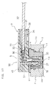
- FIG. 1 the entire structure of a connector assembly or an electrical connector assembly 1 used with the airbag system.
- the connector assembly 1 comprising a plug 3 engageable with a socket 2 is shown in the engaged state.
- the socket 2 is provided in the form of a part of an airbag igniter (which is sometimes referred to as a squib) to be electrically connected to an airbag system control system.
- an airbag igniter which is sometimes referred to as a squib
- the igniter is an explosive device which is burnt when sufficient electric energy is applied to it through two conducting wires 32 of each pair. The burning of the igniter triggers the gas generating material to be ignited and, as a result of this, the airbag is inflated.
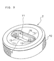
- FIG. 2 shows the socket 2 which is in the state in which the plug 3 is disengaged from the electrical connector assembly 1.
- Two, integrally molded, short-circuit elements 4 are fitted in the socket 2 with a press-fit.
- the short-circuit elements 4 put contacts of the socket 2 into the short-circuited state until the socket 2 and the plug 3 are mechanically and electrically connected with each other.
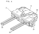
- FIG. 8 shows the plug 3 electrically connected with the control system.
- the plug 3 is to be engaged in the socket 2.
- a locking element 5 is held in the plug 3 in its locked state in the first locking position shown in the diagram (hereinafter it is simply referred to as "the first position").
- the plug 3, the short-circuit elements 4 and the locking element 5 are preferably formed of proper non-conductive plastic material, except various kinds of wires and contacts.
- the socket 2 is formed to have a cylindrical body 10 forming therein an accommodating portion 11 of a slot-like form for accommodating the two short-circuit elements 4.
- This socket 2 is well shown in FIGS. 1-3, in particular.
- the body 10 forming the accommodating portion 11 therein can be directly built in its related structure such as an igniter housing. Further, the accommodating portion 11 may be formed as a separate element so that it may be added to its related structure. In either configuration, the body 10 forming the accommodating portion 11 therein terminates at a bottom wall 12, as best shown in FIG. 3. Extended from the bottom wall 12 are two pairs of first conductive male electrical connector elements or pins 13 formed of metal.
- the socket 2 serves to support the two pairs of pins 13 in proximity so that the two pairs of pins, two for each pair, can all be arranged in series. These two pairs of pins 13 are connected to their respective conducting wires of two airbag igniters (not shown) in any conventional manner. The igniters are electrically energized through these pins 13 so that they can be ignited.
- the accommodating portion 11 of slot-like form is formed to have such a configuration that its outer circumferential part is partly folded inside at only one side of the part extending in the direction of the major axis of the slot.
- the plug 3 is made to have the configuration and dimension corresponding to those of the outer circumferential part of the accommodating part 11, so as to prevent inadequate engagement between the socket 2 and the plug 3.
- the accommodating part 11 has an inclined surface 14 formed at an entrance thereof. Also, the accommodating part 11 has a locking recess 15 formed in its inner surface to extend continuously in the circumferential direction.
- FIGS. 12-15 show the electrical connector assembly 1 in section taken along line extending in parallel with the conducting wires 32 lying in the middle of the space between the two pairs of conducting wires 32.
- the inclined surface 14 serves to receive locking portions 42 provided at elastic legs 41 of the plug 3, as mentioned later, and produce a deforming moment to move the locking portions 42 toward the center (See FIGS. 12, 13).
- the inclined surface 14 serves to receive second locking portions 55 of the locking element 5, as mentioned later, and produce a deforming moment to move the second locking portions 55 toward the center (See FIG. 14).
- the locking recess 15 serves to receive the locking portions 42 of the plug 3 and keep it in its engaged state, as best shown in FIG. 14. Also, the locking recess 15 serves to receive the second locking portions 55 of the locking element 5 and switch the locking element 5 to the second locking position (hereinafter it is simply referred to as "the second position"), as best shown in FIG. 15.
- the two short-circuit elements 4 are received in the accommodating portion 11, to be engaged with the plug 3. During the time during which the locking element 5 of the plug 3 does not assume the second position, the electrical connection is provided. Thus, the two short-circuit elements 4 serve to short-circuit the two pairs of pins 13 of the first male electrical connector elements.
- each of the two short-circuit elements 4 has a plastic body 16 of a generally cylindrical shape having a dimension to tightly fit and supported in the accommodating portion 11.
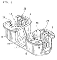
- the two short-circuit elements 4 are formed in one piece, such that they are continuously connected with each other via a bridge portion 17.
- the bridge portion 17 is provided with a reinforcing rib 19.
- the two short-circuit elements 4 have in their bodies 16 two openings 18, respectively, to receive the plug bodies 31 for supporting the two electrical terminals 30 of each pair which are the second male electrical connector elements of the plug 3 mentioned later.
- the two pairs of pins 13 are also extended passing through these two openings 18.
- the two openings 18 are formed to open to tops thereof and lateral sides thereof opposite to the side on which the bodies 16 are connected with each other via the bridge portion 17, respectively.
- the two short-circuit elements 4 have short-circuit clips 24, respectively.
- FIG. 4 shows the state of the short-circuit clips 24 before being inserted into the related short-circuit elements 4.
- FIG. 5 shows the state of the short-circuit clips 24 after being inserted into the related short-circuit elements 4.
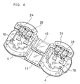
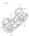
- FIGS. 6 and 7 show the short-circuit elements 4 as viewed from the top and bottom thereof, respectively.
- the short-circuit clips 24 are held in the bodies 16 of the two short-circuit elements 4, respectively.
- the short-circuit clips 24 are formed of conductive material having elasticity such as spring steel.
- the short-circuit clips 24 are partly deflected to the direction of their abutting with the both pins 13. The abutment of the short-circuit clips 24 with the pins 13 provides an electrical short-circuit therebetween.
- each of the two short-circuit clips 24 comprises a plate-form base 25, a pair of legs 26 folded back at the top of the base 25 and extending downward therefrom and a pair of abutting portions 27 folded at an angle of 90 degree at the lower portions of the pair of legs 26.
- Each of the legs 26 is folded and deflected stepwise in the direction of its being away from the base 25.
- the abutting portions 27 of the short-circuit clips 24 are brought into abutment with lateral sides of the pins 13 located at the corresponding positions, to electrically connected therewith.
- the short-circuit clips 24 are held in the bodies 16 of the short-circuit elements 4, with their bases 25 inserted in slit-like recesses 28 of the short-circuit elements 4 so as not to slip off.
- FIGS. 16 and 17 show the electrical connector assembly 1 in section taken along any plane including the conducting wire 32 and the pin 13. These figures show the short-circuit element 4 accommodated in the accommodating portion 11 and the pin 13 extending upwardly within the opening 18.
- FIG. 16 shows the state in which the pin 3 is in abutment with the abutting portion 27 of the short-circuit clip 24 and thus is in electrical connection with it.
- FIG. 17 shows the state wherein legs 26 of the short-circuit clips 24 are bent by plugging the locking element 5 mentioned later and thereby the electrical connection between the abutting portion 27 of the short-circuit clip 24 and the pin 13 is released.
- FIG. 8 is a perspective view of the plug 3 as viewed from the top;
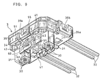
- FIG. 9 is a perspective view of the plug 3 as viewed from the bottom;
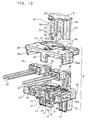
- FIG. 10 is an exploded perspective view of the plug 3.
- the plug 3 includes a plug body portion 31 extending downwardly and supporting two pairs of electrical terminals 30, two electrical terminals for each pair, which are in the form of second female electrical connector elements. These two pairs of electrical terminals 30 are electrically connected with the two pairs of conducting wires 32. Also, these two pairs of electrical terminals 30 are engaged with the two pairs of pins 13 or first male electrical connector elements, respectively, so as to be electrically connected therewith. Each pair of electrical terminals 30 are supported as a unit by the plug 3. Also, the electrical terminals 30 are formed to have configuration and size to receive the pins 13 therein and are mounted to extend in parallel with each other.
- the two electrical terminals 30 of each pair built in the central plug portion 31 each have a conducting wire connecting portion 33 for connecting one of the conducting wires 32.
- the conducting wire connecting portions 33 are provided in the electrical terminals 30 at their portions which extend from the tubular terminal portions forming the second female connector element and change in direction in a generally L-form.
- the conducting wires 32 are the insulation armored wires. Insulating coatings of the conducting wires 32 are peeled at the ends thereof so as to be electrically and mechanically attached to the conducting wire connecting portion 33 to which the conducting wires are connected. The attachment of the wires is usually performed by press-fitting a part of the conducting wire connecting portions 33 around the bare wires at the ends thereof in any conventional manner.
- the two pairs of conducting wires 32 pass through ferrite beads 35 placed in a box-shaped room 37 formed at a lower portion 34 of the plug 3.
- the bead 35 is a generally box-shaped homogeneous substance used for providing the noise filtering out function.
- Each bead 35 has two tubular thru holes extending in parallel with each other, through which the conducting wires 32 pass.
- the conducting wires 32 are extended out from an end of the lower portion 34, passing through an opening of a rear wall 38 of the room 37.
- the lower portion 34 of the plug 3 is provided, at a bottom side thereof, with two plug bodies 31 of a generally square cylinder shape and two elastic legs 41.
- the two elastic legs 41 are disposed between the two plug bodies 31, such that a generally cross-shape is formed by a line connecting between the two elastic legs 41 and a line connecting between the two plug bodies 31.
- the two elastic legs 41 have, on their outside surfaces, locking portions 42 to be engaged in the locking recess 15 formed in the inside of the accommodating portion 11, as previously mentioned, and the locking portions 42 are formed by outwardly protruding lugs (See FIGS. 9, 10 and 11).
- the locking portions 42 are so located and sized as to be fitted in the locking recess 15 when the plug 2 is adequately engaged with the socket 2.
- the two plug bodies 31 are so located and sized as to provide frames having enough rigidity for the plug 3 to be disposed in the accommodating portion 11 formed in the socket 2.
- the plug bodies 31 have ridges 43.
- the ridges 43 are so sized and located as to be engaged with recesses 29, as shown in FIGS. 2 and 5.
- the engagement between the ridges 43 and the recesses 29 ensures the correct connection between the electrical terminals 30 of the plug 3 and the pins 13 of the socket 2.
- the plug 3 further has an upper portion 36 that covers end portions of the conducting wires 32 and the beads 35 and engages with the lower portion 34.
- the upper portion 36 and the lower portion 34 are combined into a general rectangular parallelepiped shape by engagement of a pair of locking portions 39a, 39b which are provided in two opposite side surfaces of the upper and lower portions, respectively.
- the upper portion 36 and the lower portion 34 are locked in their properly engaged state by the engagement between the pair of locking portions 39a, 39b.
- the upper portion 36 has downwardly extending projections 48 which are so sized and located as to fit in concave portions 44 formed in the side surfaces of the lower portion 34. The projections 48 subserve to position the upper portion 36 with respect to the lower portion 34.
- the upper portion 36 of the plug 3 has a wide shallow recess 45 formed in an upper surface thereof at a corresponding location over the plug bodies 31.
- a pair of first perforated openings 46 which are arranged opposite to each other in a generally L-shape with respect to the sides of the plug bodies 31, are formed in the recess 45 at both widthwise sides thereof.
- a pair of second perforated openings 47 which are arranged opposite to each other in a generally T-shape, such that a generally cross-shape is formed by a line connecting between the pair of first perforated openings 46 and a line connecting between the pair of second perforated openings 47, are formed in the recess 45 at both lengthwise sides thereof.
- the locking element 5 includes a head portion or pressing portion 50, a pair of first legs 51 extending substantially in parallel with each other and a pair of second legs 52 extending substantially in parallel with each other.
- the pair of first legs 51 are formed to extend downwardly from both widthwise sides of the pressing portion 50.
- the pair of first legs 51 each have a cross section of a generally inverted L-shape.
- the pair of first legs 51 serve to release the short circuits between the two pairs of first electrical connecter elements 13 when the plug 3 and the socket 2 are engaged with each other.
- the locking element 5 is inserted in the plug 3, with their inverted L-shaped legs fitted in the pair of perforated openings 46, respectively (See FIG. 8).
- the pair of first legs 51 are so sized and located as to allow two sides of each of the inverted L-shaped legs to be inserted along two sides of each of the plug bodies 31.
- the pair of second legs 52 are arranged at such locations that a generally cross-shape is formed by a line connecting between the pair of first legs 51 and a line connecting between the pair of second legs 52 and are formed to extend downwardly, respectively.
- the pair of second legs 52 have the locking portions formed to project outwardly.
- the locking portions each have a first locking portion 54 and a second locking portion 55 which are vertically arranged in the ascending order.
- the first locking portion 54 is formed to project outwardly to a small extent and the second locking portion 55 is formed to project outwardly to a large extent.
- the first locking portion 54 has, at its front end, a step portion 54a (See FIG. 12).
- the provision of the first locking portion 54 enables the locking element 5 to be locked at the first position with respect to the plug 3 and the socket 2, and the provision of the second locking portion 55 enables the locking element 5 to be locked at the second position with respect to the plug 3 and the socket 2.
- the pair of second legs 52 each have two restraint portions 53 which are formed at both lateral sides thereof to extend downwardly in parallel with each other.
- FIGS. 12-15 show the electrical connecter assembly 1 in section taken along the plane including the pair of second legs 52 of the locking element 5.
- step portions 61 are formed at lower end portions of openings 60 of the elastic legs 41 of the plug 3.
- the step portions 54a of the second legs 52 are brought into abutment with the step portions 61 of the elastic legs 41 and thereby are put into the locked state at the first position.
- the second locking portions 55 of the locking element 5 come to project outwardly from the opening 60 and thus are put in the operable state.
- the elastic legs 41 each have an inwardly hollowed locking recess 62 formed in its interior at the lower end portion thereof.
- the locking element 5 When an outward projecting portion of the first locking portion 54 of the locking element 5 shifted from the first position is engaged in the locking recess 62, the locking element 5 is locked in the second position.
- the locking element 5 is locked in the second position to an extent that can permit the locking element 5 to be restored to the first position when it is pulled up from the plug 3.
- the restraint portions 53 at both lateral sides of the second legs 52 are spaced from the second legs 52 via the slits 56, so as not to hinder the elastic deformation of the second legs 52. Also, the restraint portions 53 are tapered so that their thicknesses are gradually decreased toward the lower ends.
- the restraint portions 53 are placed on the inside of the elastic legs 41, respectively.
- the locking element 5 is in the locked position of the first position, the deformation of the elastic legs 41 toward the inside of the locking portions 42 is not restrained by the restraint portions 53.
- the restraint portions 53 are placed in position with their thicknesses decreased.
- the locking element 5 thus constructed can be allowed to be locked in the first position with respect to the plug 3 and also can be allowed to be shifted to the second position where the two short-circuit clips 24 of the two short-circuit elements 4 are simultaneously moved back to their non-short-circuit positions when the plug 3 is engaged with the socket 2.
- This action of the short-circuit clips 24 moving back to their non-short-circuit positions will be well understood from FIGS. 16 and 17.
- the locking element 5, when pressed in from the first position to the second position allows the first legs 51 to be advanced up to the folded portions of the short-circuit clips 24, and as such can allow the abutting portions 27 to move away from the pins 13 to release the electrical short-circuit connection with the pins 13.
- the locking element 5 can allow the socket 2 and the plug 3 to be engaged with each other in such a manner as to prevent them from being separated from each other; can allow them to be electrically connected with each other; and can further allow the short circulation provided by the two short-circuit elements 4 to be released simultaneously.
- the structure of the electrical connector assembly having these characteristic features can be realized with ease.
- FIG. 2 the two short-circuit elements 4 are previously fitted in the accommodating portion 11 of the socket 2 to short-circuit the two pairs of pins 13.
- the locking element 5 is previously locked in the first position with respect to the plug 3 or is previously locked, with the first locking portions 54 abutted with the step portions 61.
- the head portion 50 of the locking element 5 remains spaced from the recess 45 of the plug 3, and this state of the connecter assembly can be visually checked.
- the second locking portions 55 of the second legs 52 are fitted in the locking recess 15, as shown in FIG. 15, and the locking element 5 is set in the second position in which the first locking portion 54 of the second legs 52 are locked in the locking recess 62.
- the restraint portions 53 of the locking element 5 are placed in position with their thicknesses decreased, though not shown, to restrain the locking portions 42 from being disengaged from the locking recess 15.
- the plug 3 is prevented from being disengaged from the socket 2.
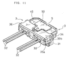
- the head portion 50 of the locking element 5 is sunk in the recess 45 of the plug 3, as well understood from FIG. 11, from the state of which one can visually check that the mechanical engagement between the socket 2 and the plug 3 is perfectly completed.
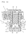
- FIG. 16 shows the state that the socket 2 and the plug 3 are in engagement with each other before the locking element 5 is pressed further.
- the front ends of the first legs 51 of the locking element 5 do not reach step-like folded portions of the short-circuit clips 24 at intermediate portion thereof, so that the abutting portions 27 are still in abutment with the side surfaces of the pins 13 to keep the short-circuit condition.
- the locking element 5 is pressed further and is brought into complete mechanical engagement, the state of which is shown in FIG. 17.
- the step-like folded portions of the short-circuit clips 24 at intermediate portions thereof are stretched by the front ends of the first legs 51 of the locking element 5.
- the abutting portions 27 are moved away from the side surfaces of the pins 13 to release the short circuit between the pins 13, and the electrical engagement is also ended completely.
- the direction for the plug 3 to be engaged with the socket 2 is identical with the direction for the locking element 5 to be shifted from the first position to the second position.
- This can provide the result that the engagement of the plug 3 with the socket 2 and the shifting of the locking element 5 from the first position to the second position can both be performed in the same pressing motion of the locking element 5.
- the mechanical engagement between the plug 3 and the socket 2 and the electrical connection therebetween can be completely ended in the single motion.
- the socket 2 is constructed to support the two pairs of first electrical connector elements 13 in proximity. This can eliminate the need to arrange the two sockets while making a position adjustment to bring the electrical contacts of each pair into alignment in series in each of the sockets, thus providing the result of facilitating the effective use of the connection space.
- the plug 3 is constructed to support the two pairs of second electrical connector elements 30 as a unit, the double action commonly required for the engagement of the connector assembly can be reduced in half to the single operation.
- the socket and the plug can be engaged with each other in only a limited orientation, the need to distinguish the two connector assemblies by using different colors or shapes for the purpose of preventing improper connection of the two connector assemblies is eliminated to begin with.
- the need to check the fitting positions of the connector assemblies is eliminated to begin with.
- the integrally formed locking element 5 can allow the two short-circuit elements 4 to move back to their non-short-circuit positions simultaneously, the release of short-circuit can be completed in only a single operation.
- the present invention can provide an electrical connector assembly having a locking part that can provide a drastically improved working efficiency and thus provide excellent connection workability even when two pairs of electrical contacts are connected with each other.
- the two short-circuit elements 4 are also integrally formed as a unit, possible mistakes, such as the case that the two separate short-circuit elements may be wrongly assembled, can be prevented. Besides, the assembling work of the short-circuit elements 4 can be completed in only a single operation, and as such can provide an electrical connector assembly having a locking part of excellent in workability. Also, since the plug 3 is constructed to be received in the openings 18 of the integrally formed short-circuit elements 4, the stable connecting structure can be provided for even the connector assembly having two pairs of electrical connector elements.
- the locking element 5 which is previously locked at the first position with respect to the plug 3, is pressed down, the plug 3 is engaged with the socket 2 and also the locking element 5 locked at the first position is released simultaneously and then is pressed further into the second position.
- the locking element 5 operates to release the short-circuit of the short-circuit element 4 when it is in the second position.
- the connecting operation of the plug 3 and the socket 2 and the pressing operation of the locking element 5 to release the short circuit of the short-circuit elements 4 can be performed in the same motion as a whole.
- the pair of legs 26 of the short-circuit clip 24 may be presented in the form of a sheet of plate.
- the pair of abutting portions 27 formed by bending the front ends of the legs 26 at an angle of 90 degree may take any suitable configuration to directly contact with the pins 13, without limiting to the configuration as shown in the illustrated embodiment.
- the two short-circuit elements 4 may be formed into any suitable configuration, without limiting to the configuration wherein the two short-circuit elements 4 are connected to each other via the bridge portion 17, as in the illustrated embodiment.
- the two short-circuit elements 4 may be formed into an elliptic cylinder form or a like form.
- the locking element 5 according to the present invention is applicable not only to the electrical connector assembly 1 according to the present invention that is so structured that the locking and the release of the short circuit can both be performed in the same motion, but also to a conventional type of electrical connector assembly that is so structured that the locking and the release of the short circuit are performed by different motions.
Landscapes
- Details Of Connecting Devices For Male And Female Coupling (AREA)
- Connector Housings Or Holding Contact Members (AREA)
Applications Claiming Priority (2)
| Application Number | Priority Date | Filing Date | Title |
|---|---|---|---|
| JP2001189118 | 2001-06-22 | ||
| JP2001189118A JP3607883B2 (ja) | 2001-06-22 | 2001-06-22 | 掛け止めを有する電気的接続装置 |
Publications (3)
| Publication Number | Publication Date |
|---|---|
| EP1271709A2 true EP1271709A2 (fr) | 2003-01-02 |
| EP1271709A3 EP1271709A3 (fr) | 2008-11-26 |
| EP1271709B1 EP1271709B1 (fr) | 2010-05-26 |
Family
ID=19028089
Family Applications (1)
| Application Number | Title | Priority Date | Filing Date |
|---|---|---|---|
| EP02291488A Expired - Lifetime EP1271709B1 (fr) | 2001-06-22 | 2002-06-14 | Arrangement de Connecteur électrique avec système de verrouillage |
Country Status (7)
| Country | Link |
|---|---|
| US (1) | US6780036B2 (fr) |
| EP (1) | EP1271709B1 (fr) |
| JP (1) | JP3607883B2 (fr) |
| KR (1) | KR20030001285A (fr) |
| CN (1) | CN1232006C (fr) |
| DE (1) | DE60236483D1 (fr) |
| TW (1) | TW544978B (fr) |
Families Citing this family (16)
| Publication number | Priority date | Publication date | Assignee | Title |
|---|---|---|---|---|
| DE10329741A1 (de) * | 2003-07-02 | 2005-01-27 | Robert Bosch Gmbh | Steuergerät mit blockierenden Befestigungsstellen |
| JP4548272B2 (ja) * | 2005-08-17 | 2010-09-22 | 住友電装株式会社 | コネクタ |
| JP4613747B2 (ja) * | 2005-08-17 | 2011-01-19 | 住友電装株式会社 | コネクタ |
| US7344403B2 (en) * | 2006-01-31 | 2008-03-18 | Fci Americas Technology, Inc. | Squib connector with improved cover connection |
| JP5148894B2 (ja) * | 2007-02-23 | 2013-02-20 | 日本圧着端子製造株式会社 | コネクタ用雌端子、コネクタ及び電気的接続装置 |
| JP2009004247A (ja) * | 2007-06-22 | 2009-01-08 | Jst Mfg Co Ltd | コネクタ |
| KR101271807B1 (ko) * | 2010-07-06 | 2013-06-07 | 니혼앗짜쿠단시세이소 가부시키가이샤 | 커넥터의 장착구조 |
| JP5622490B2 (ja) * | 2010-08-25 | 2014-11-12 | 矢崎総業株式会社 | コネクタ |
| JP6279846B2 (ja) * | 2013-07-01 | 2018-02-14 | 日本圧着端子製造株式会社 | 電気コネクタ、およびスクイブの接続装置 |
| JP6310663B2 (ja) * | 2013-09-13 | 2018-04-11 | 矢崎総業株式会社 | 短絡端子付きコネクタ |
| EP3026763B1 (fr) * | 2014-11-28 | 2017-02-22 | Magneti Marelli S.p.A. | Appareil électrique avec connecteur de sécurité pour empêcher un choc électrique |
| JP6407819B2 (ja) * | 2015-07-31 | 2018-10-17 | 株式会社シマノ | 自転車用コンポーネント |
| JP2017199497A (ja) * | 2016-04-26 | 2017-11-02 | ヒロセ電機株式会社 | 端子接触防止機構を備えた電源コネクタ、及び、これを用いる電源コネクタ装置 |
| EP3396790A1 (fr) * | 2017-04-27 | 2018-10-31 | Delphi International Operations Luxembourg S.à r.l. | Ensemble de connecteur pour des systèmes de sécurité |
| EP3396789B1 (fr) * | 2017-04-27 | 2021-03-03 | Aptiv Technologies Limited | Connecteur pour des systèmes de retenue par airbag |
| CN110602599B (zh) * | 2019-10-31 | 2021-02-19 | 歌尔科技有限公司 | 无线耳机及其充电盒 |
Family Cites Families (4)
| Publication number | Priority date | Publication date | Assignee | Title |
|---|---|---|---|---|
| US5275575A (en) | 1992-10-09 | 1994-01-04 | Trw Inc. | Electrical connection system with safety interlock |
| JP3075446B2 (ja) * | 1992-12-07 | 2000-08-14 | 矢崎総業株式会社 | 多入力コネクタ |
| US5618201A (en) * | 1994-06-14 | 1997-04-08 | Yazaki Corporation | Connector having engagement detecting device |
| JP3845524B2 (ja) * | 1998-11-27 | 2006-11-15 | タイコエレクトロニクスアンプ株式会社 | 電気コネクタ |
-
2001
- 2001-06-22 JP JP2001189118A patent/JP3607883B2/ja not_active Expired - Fee Related
-
2002
- 2002-06-04 TW TW091112013A patent/TW544978B/zh not_active IP Right Cessation
- 2002-06-14 EP EP02291488A patent/EP1271709B1/fr not_active Expired - Lifetime
- 2002-06-14 DE DE60236483T patent/DE60236483D1/de not_active Expired - Lifetime
- 2002-06-20 US US10/176,713 patent/US6780036B2/en not_active Expired - Fee Related
- 2002-06-21 KR KR1020020034834A patent/KR20030001285A/ko not_active Ceased
- 2002-06-21 CN CNB021248672A patent/CN1232006C/zh not_active Expired - Fee Related
Also Published As
| Publication number | Publication date |
|---|---|
| CN1232006C (zh) | 2005-12-14 |
| DE60236483D1 (de) | 2010-07-08 |
| CN1393964A (zh) | 2003-01-29 |
| TW544978B (en) | 2003-08-01 |
| EP1271709A3 (fr) | 2008-11-26 |
| EP1271709B1 (fr) | 2010-05-26 |
| KR20030001285A (ko) | 2003-01-06 |
| US20020197897A1 (en) | 2002-12-26 |
| JP2003007393A (ja) | 2003-01-10 |
| JP3607883B2 (ja) | 2005-01-05 |
| US6780036B2 (en) | 2004-08-24 |
Similar Documents
| Publication | Publication Date | Title |
|---|---|---|
| EP1253680B1 (fr) | Ensemble de connection électrique comportant un verouillage | |
| EP1130692B1 (fr) | Système de connexion électrique | |
| JP2647336B2 (ja) | 電気接続装置 | |
| EP1271709B1 (fr) | Arrangement de Connecteur électrique avec système de verrouillage | |
| KR100282328B1 (ko) | 연동장치를가진전기접속시스템 | |
| US6203342B1 (en) | Grounding plate for orientationless squib connector assembly for automotive air bag assemblies | |
| US8317545B2 (en) | Electric connector plug and its assembly method | |
| US6544060B2 (en) | Shunt of squib | |
| EP1995827B1 (fr) | Connecteur et dispositif de connexion électrique | |
| JP2003203722A5 (fr) | ||
| JP2002075558A (ja) | 無方向性電気コネクタ | |
| US10236640B2 (en) | Electrical connector for a safety restraint system | |
| EP1420487B1 (fr) | Shunt pour amorce détonante | |
| US7147503B2 (en) | Electrical connecting device having a cover with a latch | |
| JP3650034B2 (ja) | 掛け止めを有する電気的接続装置 | |
| EP1378973B1 (fr) | Ensemble connecteur d'amorce exempt d'orientation pour un airbag d'automobile |
Legal Events
| Date | Code | Title | Description |
|---|---|---|---|
| PUAI | Public reference made under article 153(3) epc to a published international application that has entered the european phase |
Free format text: ORIGINAL CODE: 0009012 |
|
| AK | Designated contracting states |
Kind code of ref document: A2 Designated state(s): AT BE CH CY DE DK ES FI FR GB GR IE IT LI LU MC NL PT SE TR |
|
| AX | Request for extension of the european patent |
Free format text: AL;LT;LV;MK;RO;SI |
|
| PUAL | Search report despatched |
Free format text: ORIGINAL CODE: 0009013 |
|
| AK | Designated contracting states |
Kind code of ref document: A3 Designated state(s): AT BE CH CY DE DK ES FI FR GB GR IE IT LI LU MC NL PT SE TR |
|
| AX | Request for extension of the european patent |
Extension state: AL LT LV MK RO SI |
|
| 17P | Request for examination filed |
Effective date: 20090512 |
|
| AKX | Designation fees paid |
Designated state(s): DE FR GB |
|
| GRAP | Despatch of communication of intention to grant a patent |
Free format text: ORIGINAL CODE: EPIDOSNIGR1 |
|
| GRAS | Grant fee paid |
Free format text: ORIGINAL CODE: EPIDOSNIGR3 |
|
| GRAA | (expected) grant |
Free format text: ORIGINAL CODE: 0009210 |
|
| AK | Designated contracting states |
Kind code of ref document: B1 Designated state(s): DE FR GB |
|
| REG | Reference to a national code |
Ref country code: GB Ref legal event code: FG4D |
|
| REF | Corresponds to: |
Ref document number: 60236483 Country of ref document: DE Date of ref document: 20100708 Kind code of ref document: P |
|
| PGFP | Annual fee paid to national office [announced via postgrant information from national office to epo] |
Ref country code: FR Payment date: 20100701 Year of fee payment: 9 |
|
| PGFP | Annual fee paid to national office [announced via postgrant information from national office to epo] |
Ref country code: DE Payment date: 20100705 Year of fee payment: 9 |
|
| PGFP | Annual fee paid to national office [announced via postgrant information from national office to epo] |
Ref country code: GB Payment date: 20100721 Year of fee payment: 9 |
|
| PLBE | No opposition filed within time limit |
Free format text: ORIGINAL CODE: 0009261 |
|
| STAA | Information on the status of an ep patent application or granted ep patent |
Free format text: STATUS: NO OPPOSITION FILED WITHIN TIME LIMIT |
|
| 26N | No opposition filed |
Effective date: 20110301 |
|
| REG | Reference to a national code |
Ref country code: DE Ref legal event code: R097 Ref document number: 60236483 Country of ref document: DE Effective date: 20110228 |
|
| GBPC | Gb: european patent ceased through non-payment of renewal fee |
Effective date: 20110614 |
|
| REG | Reference to a national code |
Ref country code: FR Ref legal event code: ST Effective date: 20120229 |
|
| REG | Reference to a national code |
Ref country code: DE Ref legal event code: R119 Ref document number: 60236483 Country of ref document: DE Effective date: 20120103 |
|
| PG25 | Lapsed in a contracting state [announced via postgrant information from national office to epo] |
Ref country code: FR Free format text: LAPSE BECAUSE OF NON-PAYMENT OF DUE FEES Effective date: 20110630 Ref country code: DE Free format text: LAPSE BECAUSE OF NON-PAYMENT OF DUE FEES Effective date: 20120103 |
|
| PG25 | Lapsed in a contracting state [announced via postgrant information from national office to epo] |
Ref country code: GB Free format text: LAPSE BECAUSE OF NON-PAYMENT OF DUE FEES Effective date: 20110614 |