EP1271894A1 - Emetteur de paquets, recepteur de paquets et systeme d'emission de paquets - Google Patents
Emetteur de paquets, recepteur de paquets et systeme d'emission de paquets Download PDFInfo
- Publication number
- EP1271894A1 EP1271894A1 EP01902844A EP01902844A EP1271894A1 EP 1271894 A1 EP1271894 A1 EP 1271894A1 EP 01902844 A EP01902844 A EP 01902844A EP 01902844 A EP01902844 A EP 01902844A EP 1271894 A1 EP1271894 A1 EP 1271894A1
- Authority
- EP
- European Patent Office
- Prior art keywords
- identification signal
- decoding
- data
- packet
- transmission
- Prior art date
- Legal status (The legal status is an assumption and is not a legal conclusion. Google has not performed a legal analysis and makes no representation as to the accuracy of the status listed.)
- Granted
Links
Images


Classifications
-
- H—ELECTRICITY
- H04—ELECTRIC COMMUNICATION TECHNIQUE
- H04L—TRANSMISSION OF DIGITAL INFORMATION, e.g. TELEGRAPHIC COMMUNICATION
- H04L1/00—Arrangements for detecting or preventing errors in the information received
- H04L1/12—Arrangements for detecting or preventing errors in the information received by using return channel
- H04L1/16—Arrangements for detecting or preventing errors in the information received by using return channel in which the return channel carries supervisory signals, e.g. repetition request signals
- H04L1/18—Automatic repetition systems, e.g. Van Duuren systems
- H04L1/1867—Arrangements specially adapted for the transmitter end
- H04L1/1887—Scheduling and prioritising arrangements
-
- H—ELECTRICITY
- H04—ELECTRIC COMMUNICATION TECHNIQUE
- H04L—TRANSMISSION OF DIGITAL INFORMATION, e.g. TELEGRAPHIC COMMUNICATION
- H04L1/00—Arrangements for detecting or preventing errors in the information received
- H04L1/12—Arrangements for detecting or preventing errors in the information received by using return channel
- H04L1/16—Arrangements for detecting or preventing errors in the information received by using return channel in which the return channel carries supervisory signals, e.g. repetition request signals
- H04L1/18—Automatic repetition systems, e.g. Van Duuren systems
- H04L1/1829—Arrangements specially adapted for the receiver end
-
- H—ELECTRICITY
- H04—ELECTRIC COMMUNICATION TECHNIQUE
- H04L—TRANSMISSION OF DIGITAL INFORMATION, e.g. TELEGRAPHIC COMMUNICATION
- H04L69/00—Network arrangements, protocols or services independent of the application payload and not provided for in the other groups of this subclass
- H04L69/30—Definitions, standards or architectural aspects of layered protocol stacks
- H04L69/32—Architecture of open systems interconnection [OSI] 7-layer type protocol stacks, e.g. the interfaces between the data link level and the physical level
- H04L69/322—Intralayer communication protocols among peer entities or protocol data unit [PDU] definitions
- H04L69/326—Intralayer communication protocols among peer entities or protocol data unit [PDU] definitions in the transport layer [OSI layer 4]
-
- H—ELECTRICITY
- H04—ELECTRIC COMMUNICATION TECHNIQUE
- H04L—TRANSMISSION OF DIGITAL INFORMATION, e.g. TELEGRAPHIC COMMUNICATION
- H04L1/00—Arrangements for detecting or preventing errors in the information received
- H04L1/12—Arrangements for detecting or preventing errors in the information received by using return channel
- H04L1/16—Arrangements for detecting or preventing errors in the information received by using return channel in which the return channel carries supervisory signals, e.g. repetition request signals
- H04L1/1607—Details of the supervisory signal
Definitions
- the present invention relates to a packet transmitting device, a packet receiving device and a packet transmission system for fast packet transmission or reception.
- the S & W system (Stop & Wait system) is regarded as promising from the viewpoint of speedups in packet transmission.
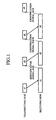
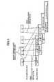
- Fig. 1 is an explanatory diagram showing ARQ of a conventional packet transmission system.
- the packet receiving device transmits an identification signal to the packet transmitting device upon completion of decoding of data.
- the packet transmitting device transmits the next data to the packet receiving device, whereas when receiving the NACK signal, the packet transmitting device retransmits the immediately previous data to the packet receiving device.
- the present invention is intended to solve the above problem, and has for its object to provide a packet transmitting device, a packet receiving device and a packet transmission system that permit speedups of the packet transmission.
- the packet transmitting device is provided with first control means that receives a first identification signal sent from a packet receiving device and, when the first identification signal is indicative of permission of transmission of the next data, instructs transmitting means to transmit the next data and, when the first identification signal is indicative of inhibition of transmission of the next data, instructs the transmitting means to retransmit the data concerned.
- This arrangement allows efficient transmission of data, and hence permits speedups of the packet transmission.
- the packet receiving device is provided with identification signal generating means that: sends a first identification signal indicative of whether to permit or inhibit transmission of the next data to the packet transmitting device prior to completion of data decoding by decoding means; and sends a second identification signal indicative of whether the data decoding is successful or not to the packet transmitting device after completion of the decoding.
- the packet transmission system is provided with: identification signal generating means that sends a first identification signal indicative of whether to permit or inhibit transmission of the next data to the packet transmitting device prior to completion of data decoding by decoding means, and sends a second identification signal indicative of whether the data decoding is successful or not to the packet transmitting device after completion of the decoding; and first control means that receives the first identification signal sent from the identification signal generating means and, when the first identification signal is indicative of permission of transmission of the next data, instructs transmitting means to transmit the next data and, when the first identification signal is indicative of inhibition of transmission of the next data, instructs the transmitting means to retransmit the data concerned.
- the packet receiving device is adapted to generate the first identification signal based on the result of reception of data by receiving means.
- the packet receiving device is adapted to generate the first identification signal based on quality information about the data received by receiving means.
- the packet receiving device is adapted to generate the first identification signal based on the intermediate result of decoding by decoding means.
- the packet receiving device is adapted to generate the second identification signal based on ultimate result of decoding by decoding means.
- This scheme ensures reception of correct data.
- the packet receiving device is adapted to determine the transmission of the first identification signal in consideration of the decoding power of the decoding means.
- This scheme permits reduction of the amount of storage in the packet receiving device.
- the packet transmitting device is adapted to instruct the transmission of data only when the packet receiving device is currently capable of decoding.
- This scheme also permits reduction of the amount of storage in the packet receiving device.
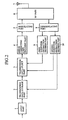
- Fig. 2 is a block diagram illustrating a packet transmitting device according to Embodiment 1 of the present invention.
- reference numeral 1 denotes an input part for inputting data
- 2 denotes a transmission data storage part for storing the data input via the input part 1
- 3 denotes a transmission data select part for selecting data to be transmitted among from the pieces of data stored in the transmission data storage part 2
- 4 denotes an error correcting code part for encoding the data selected by the transmission data select part 3
- 5 denotes a modulating part for modulating the data encoded by the error correcting code part 4
- 6 denotes an RF part for transmitting the modulated wave from the modulating part 5 via an antenna 7
- 7 denotes the antenna.
- the input part 1, the transmission data storage part 2, the transmission data select part 3, the error correcting code part 4, the modulating part 5, the RF part 6 and the antenna 7 constitute transmitting means.
- Reference numeral 8 denotes a demodulating part that demodulates a first or second identification signal when the RF part 6 receives it from a packet receiving device; 9 denotes a first identifier extraction decision part (first control means) that, when the first or second identification signal demodulated by the demodulating part 8 is an ACK signal, instructs the transmission data select part 3 to transmit the next data but, when the first identification signal is an NACK signal, instructs the transmission data select part 3 to retransmit the data concerned; and 10 denotes a second identifier extraction decision part (second control means) that, when the second identification signal demodulated by the demodulating part 8 is an ACK signal, instructs the transmission data storage part 2 to discard the data concerned, but when the first identification signal is an NACK signal, instructs the transmission data select part 3 to retransmit the data concerned.
- first control means that, when the first or second identification signal demodulated by the demodulating part 8 is an ACK signal, instructs the transmission data select part 3 to transmit the next data
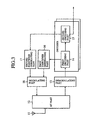
- Fig. 3 is a block diagram illustrating a packet receiving device according to Embodiment 1 of the present invention.
- reference numeral 11 denotes an antenna 12 denotes an RF part for receiving data sent from the packet transmitting device; and 13 denotes a demodulating part for demodulating the data received by the RF part 12.
- the antenna 11, the RF part 12 and the demodulating part 13 constitute receiving means.
- Reference numeral 14 denotes a first decoding part that decodes partway the data demodulated by the demodulating part 13; and 15 denotes a second decoding part that starts decoding following the first decoding part 14 and obtains the ultimate result of decoding.
- the first and second decoding parts 14 and 15 constitute a decoder (decoding means).
- Reference numeral 16 denotes a first identifier generating part that generates a first identification signal based on the result of decoding by the first decoding part 14; 17 denotes a second identifier generating part that generates a second identification signal based on the result of decoding by the second decoding part 15; and 18 denotes a modulating part which modulates the first or second identification signal.
- the antenna 11, the RF part 12, the first identifier generating part 16, the second identifier generating part 17 and the modulating part 18 constitute identification signal generating means.
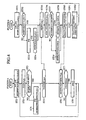
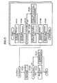
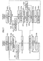
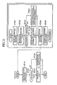
- Figs. 4 and 5 are flowcharts showing the contents of processing in the packet transmission system according to Embodiment 1 of the present invention
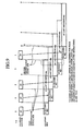
- Fig. 6 is an explanatory diagram showing ARQ of the packet transmission system.
- the transmission data storage part 2 Upon input of data to the input part 1 of the packet transmitting device, the transmission data storage part 2 stores the data (steps ST1, ST2).
- the transmission data select part 3 selects the data to be sent from among the pieces of data stored in the transmission data storage part 2. For convenience of explanation, let it be assumed that data sig-n is selected.
- the error correcting code part 4 encodes the data selected by the transmission select part 3, then the modulating part 5 modes the data encoded by the error correcting code part 4, and the RF part 6 radios the modulated wave from the modulating part 5 via the antenna 7 (steps ST3 to ST5).
- the RF part 12 of the packet receiving device receives the data sent from the packet transmitting device, and the demodulating part 13 demodulates the data received by the RF part 12 (step ST55).
- the packet receiving device performs initialization of various variables prior to receiving data (steps ST51 to ST54).
- the first decoding part 14 decodes partway the data demodulated by the demodulating part 13 (step ST56).
- the first identifier generating part 14 refers to a check bit such as CRC to decide whether the decoding carried out partway is successful (step ST57).
- the first identifier generating part When the decoding is successful, the first identifier generating part generates an ACK signal as the first identification signal as depicted in Fig. 6 (step ST58).
- the first identifier generating part On the other hand, when the decoding is unsuccessful, the first identifier generating part generates an NACK signal as the first identification signal (step ST59) since further decoding is meaningless.
- the invention is not limited specifically thereto but may also be adapted to refer to, for instance, the result of decoding of TFCI (Transport Format combination Indicator) transmitting channel multiplex information by 3GPP (3 rd Generation Partnership Project) specification, or the result of reception of a known pattern.
- TFCI Transport Format combination Indicator
- the modulating part 18 modulates the first identification signal generated by the first identifier generating part 16, and the RF part 12 transmits the modulated wave from the modulating part 18 via the antenna 11 (step ST60).
- the demodulating part 8 of the packet receiving device demodulates the first identification signal that the RF part 6 receives from the packet receiving device (step ST6).
- the first identifier extraction decision part 9 decides whether the first identification signal demodulated by the demodulating part 8 is an ACK signal or NACK signal (step ST7).
- the first identifier extraction decision part instructs the transmission data select part 3 to transmit the next data (step ST8).
- the first identifier extraction decision part instructs the transmission data select part 3 to retransmit the data concerned.
- the packet transmitting device transmits the next data or the immediately previous data to an (i+1)-th decoder.
- decoding of data d3 is unsuccessful and is retransmitted.
- the second decoding part 15 of the packet receiving device resumes decoding following the first decoding part 14, obtaining the ultimate result of decoding (steps ST61, ST62, ST101, ST102).
- the second identifier generating part 17 decides whether the ultimate decoding is successful or not (step ST103).
- the second identifier generating part When the decoding is successful, the second identifier generating part generates an ACK signal as the second identification signal as shown in Fig. 6 (step ST104).
- the second identifier generating part On the other hand, when the decoding is unsuccessful, the second identifier generating part generates an NACK signal as the second identification signal (step ST105).
- the modulating part 18 modulates the second identification signal generated by the second identifier generating part 17, and the RF part 12 transmits the modulated wave from the modulating part 18 via the antenna 11 (steps ST106, ST107).
- the demodulating part 8 of the packet transmitting device demodulates the second identification signal the RF part 6 receives from the packet receiving device (step ST151).
- the second identifier extraction decision part 10 decides whether the second identification signal demodulated by the demodulating part 8 is an ACK signal or NACK signal (step ST152).
- the second identifier extraction decision part instructs the transmission data storage part 2 to discard the data concerned (step ST153).
- the second identification signal is an NACK signal
- the second identifier extraction decision part instructs the transmission data select part 3 to retransmit the data concerned (step ST154).
- the first identification signal indicating whether to permit the transmission of the next data is sent to 5 the packet transmitting device; hence, when the whole decoding is very likely to fail, it is possible to request retransmission of the data concerned before the second decoding part 15 starts decoding.
- This provides increased packet transmission efficiency and hence allows speedups of packet transmission.
- Embodiment 1 has been described to generate the first identification signal based on the intermediate result of decoding, the first identification signal may be generated based on the result of reception of data by the RF part 12.
- the first identification signal may be generated based on quality information about the data received by the RF part 12.
- Embodiment 1 has been described to generate the first identification signal based on the intermediate result of decoding, provision may be made to determine the transmission of the first identification signal taking into consideration of the decoding power of the decoders forming the first and second decoding parts 14 and 15.
- step ST63 in Fig. 7 it is decided whether there is present a decoder currently in OFF state (step ST63 in Fig. 7), and only when such an OFF-state decoder, the first identification signal is sent to the packet transmitting device (see Fig. 9).
- This scheme permits reduction of the amount of storage in the packet receiving device.
- Embodiment 1 has been described to generate the first identification signal based on the intermediate result of decoding, provision may be made to instruct the transmission of data only when the packet receiving device is currently capable of decoding.
- step ST9 in Fig. 10 it is decided whether there is present a decoder currently in OFF state (step ST9 in Fig. 10), and only when such an OFF-state decoder, the transmission of data is instructed.
- This scheme also permits reduction of the amount of storage in the packet receiving device.
- the packet transmission system according to the present invention and the associated devices effectively allow reduction of decoding of no use and hence permit speedups of the packet transmission.
Landscapes
- Engineering & Computer Science (AREA)
- Computer Networks & Wireless Communication (AREA)
- Signal Processing (AREA)
- Computer Security & Cryptography (AREA)
- Detection And Prevention Of Errors In Transmission (AREA)
- Mobile Radio Communication Systems (AREA)
- Communication Control (AREA)
- Data Exchanges In Wide-Area Networks (AREA)
- Small-Scale Networks (AREA)
Applications Claiming Priority (1)
| Application Number | Priority Date | Filing Date | Title |
|---|---|---|---|
| PCT/JP2001/000984 WO2002065734A1 (fr) | 2001-02-13 | 2001-02-13 | Emetteur de paquets, recepteur de paquets et systeme d'emission de paquets |
Publications (3)
| Publication Number | Publication Date |
|---|---|
| EP1271894A1 true EP1271894A1 (fr) | 2003-01-02 |
| EP1271894A4 EP1271894A4 (fr) | 2003-06-18 |
| EP1271894B1 EP1271894B1 (fr) | 2005-05-04 |
Family
ID=11737017
Family Applications (1)
| Application Number | Title | Priority Date | Filing Date |
|---|---|---|---|
| EP01902844A Expired - Lifetime EP1271894B1 (fr) | 2001-02-13 | 2001-02-13 | Emetteur de paquets, recepteur de paquets et systeme d'emission de paquets |
Country Status (6)
| Country | Link |
|---|---|
| US (1) | US20030112747A1 (fr) |
| EP (1) | EP1271894B1 (fr) |
| JP (1) | JPWO2002065734A1 (fr) |
| CN (1) | CN1270498C (fr) |
| DE (1) | DE60110571T2 (fr) |
| WO (1) | WO2002065734A1 (fr) |
Cited By (3)
| Publication number | Priority date | Publication date | Assignee | Title |
|---|---|---|---|---|
| WO2011139191A1 (fr) | 2010-05-04 | 2011-11-10 | Telefonaktiebolaget L M Ericsson (Publ) | Procédés et agencements pour rétroaction harq précoce dans un système de communication mobile |
| EP2559201A4 (fr) * | 2010-04-12 | 2017-07-26 | Qualcomm Incorporated | Accusés de réception retardés pour communication à faible surdébit dans réseau |
| US11005603B2 (en) | 2015-12-01 | 2021-05-11 | Telefonaktiebolaget Lm Ericsson (Publ) | Predictive acknowledgment feedback mechanism |
Families Citing this family (4)
| Publication number | Priority date | Publication date | Assignee | Title |
|---|---|---|---|---|
| JP4572933B2 (ja) * | 2007-12-14 | 2010-11-04 | 富士通株式会社 | 受信装置及び再送制御方法 |
| US8787384B2 (en) * | 2008-05-05 | 2014-07-22 | Qualcomm Incorporated | Pre-emptive acknowledgement for data transmission in a communication system |
| CN108631960B (zh) * | 2017-03-24 | 2021-08-20 | 华为技术有限公司 | 一种数据传输方法和相关设备 |
| JP7257249B2 (ja) * | 2019-05-17 | 2023-04-13 | 日本放送協会 | 送信サーバ、送信装置、受信装置及びプログラム |
Family Cites Families (9)
| Publication number | Priority date | Publication date | Assignee | Title |
|---|---|---|---|---|
| WO1995001020A1 (fr) * | 1993-06-25 | 1995-01-05 | Xircom, Incorporated | Detection de porteuses virtuelles pour reseau local de transmission sans fil a commande repartie |
| JPH0832598A (ja) * | 1994-07-20 | 1996-02-02 | Hitachi Ltd | 連続メディアの蓄積・伝送システム |
| US5799012A (en) * | 1995-08-11 | 1998-08-25 | Motorola, Inc. | System controlled asymmetrical automatic repeat request protocol method |
| TW313734B (en) * | 1996-01-05 | 1997-08-21 | Motorola Inc | System controlled asymmetrical automatic repeat request protocol method |
| JP3001435B2 (ja) * | 1996-10-24 | 2000-01-24 | 日本電気移動通信株式会社 | 確認形情報転送におけるデータ再送方法 |
| JPH1146217A (ja) * | 1997-07-28 | 1999-02-16 | Nippon Telegr & Teleph Corp <Ntt> | 無線パケット再送方法 |
| JP3449204B2 (ja) * | 1998-01-23 | 2003-09-22 | ソニー株式会社 | 制御装置、無線伝送装置及び無線伝送方法 |
| US6359877B1 (en) * | 1998-07-21 | 2002-03-19 | Telefonaktiebolaget Lm Ericsson (Publ) | Method and apparatus for minimizing overhead in a communication system |
| US6301249B1 (en) * | 1998-08-04 | 2001-10-09 | Opuswave Networks, Inc | Efficient error control for wireless packet transmissions |
-
2001
- 2001-02-13 DE DE60110571T patent/DE60110571T2/de not_active Expired - Fee Related
- 2001-02-13 WO PCT/JP2001/000984 patent/WO2002065734A1/fr not_active Ceased
- 2001-02-13 EP EP01902844A patent/EP1271894B1/fr not_active Expired - Lifetime
- 2001-02-13 JP JP2002564920A patent/JPWO2002065734A1/ja active Pending
- 2001-02-13 CN CNB018079288A patent/CN1270498C/zh not_active Expired - Fee Related
- 2001-02-13 US US10/239,860 patent/US20030112747A1/en not_active Abandoned
Non-Patent Citations (5)
| Title |
|---|
| AYANOGLU E ET AL: "AIRMAIL: A LINK-LAYER PROTOCOL FOR WIRELESS NETWORKS" WIRELESS NETWORKS, ACM, US, vol. 1, no. 1, 1 February 1995 (1995-02-01), pages 47-59, XP000503720 ISSN: 1022-0038 * |
| BENELLI G ET AL: "NEW MODIFIED STOP-AND-WAIT ARQ PROTOCOLS FOR MOBILE COMMUNICATIONS" WIRELESS PERSONAL COMMUNICATIONS, KLUWER ACADEMIC PUBLISHERS, NL, vol. 1, no. 2, 1994, pages 117-126, XP000511623 ISSN: 0929-6212 * |
| LUCENT 3GPP TSG RAN WG1 TSGR1 # 17(00)1384: "Text proposal for the HSDPA technical report TSGR1 # 17(00)1384" 3GPPP TSG RAN WORKING GROUP 1, 21 - 24 November 2000, XP002235321 * |
| LUCENT TECHNOLOGIES: "TSG-RAN#17(00)1382:Asynchronous and Adaptive IR for HSDPA" 3GPPP TSG RAN WORKING GROUP 1, 25 November 2000 (2000-11-25), XP002190696 Retrieved from the Internet: <URL:www.3gpp.org> [retrieved on 2000-11-25] * |
| See also references of WO02065734A1 * |
Cited By (5)
| Publication number | Priority date | Publication date | Assignee | Title |
|---|---|---|---|---|
| EP2559201A4 (fr) * | 2010-04-12 | 2017-07-26 | Qualcomm Incorporated | Accusés de réception retardés pour communication à faible surdébit dans réseau |
| WO2011139191A1 (fr) | 2010-05-04 | 2011-11-10 | Telefonaktiebolaget L M Ericsson (Publ) | Procédés et agencements pour rétroaction harq précoce dans un système de communication mobile |
| US9294234B2 (en) | 2010-05-04 | 2016-03-22 | Telefonaktiebolaget L M Ericsson (Publ) | Methods and arrangements for early HARQ feedback in a mobile communication system |
| EP3206322A1 (fr) * | 2010-05-04 | 2017-08-16 | Telefonaktiebolaget LM Ericsson (publ) | Procédés et agencements pour rétroaction harq précoce dans un système de communication mobile |
| US11005603B2 (en) | 2015-12-01 | 2021-05-11 | Telefonaktiebolaget Lm Ericsson (Publ) | Predictive acknowledgment feedback mechanism |
Also Published As
| Publication number | Publication date |
|---|---|
| US20030112747A1 (en) | 2003-06-19 |
| CN1422486A (zh) | 2003-06-04 |
| EP1271894A4 (fr) | 2003-06-18 |
| EP1271894B1 (fr) | 2005-05-04 |
| HK1055520A1 (en) | 2004-01-09 |
| WO2002065734A1 (fr) | 2002-08-22 |
| DE60110571D1 (de) | 2005-06-09 |
| CN1270498C (zh) | 2006-08-16 |
| DE60110571T2 (de) | 2006-02-23 |
| JPWO2002065734A1 (ja) | 2004-06-17 |
Similar Documents
| Publication | Publication Date | Title |
|---|---|---|
| TWI320273B (en) | Method and apparatus for augmenting physical layer arq in a wireless data communication system | |
| US9356739B2 (en) | Method and system for providing autonomous retransmissions in a wireless communication system | |
| JP3381795B2 (ja) | 移動通信システムの逆方向共通チャネルにおける連続した使用者データ伝送方法 | |
| JP4068165B2 (ja) | 反復送信プロトコルを選択するシーケンス付番範囲の拡張方法およびシステム | |
| JP6121482B2 (ja) | 下り回線無線データ伝送のブラインド復号において既知のレート・マッチング情報を活用すること | |
| JP2006504337A5 (fr) | ||
| CN101841402A (zh) | 反向链路自动重复请求 | |
| JP2002281003A (ja) | パケット伝送システム及びパケット伝送方法 | |
| WO2006030019A3 (fr) | Procede de decodage | |
| EP1684455B1 (fr) | Procede de communication, terminal et station de base | |
| US8792418B2 (en) | Method for handling corrupted signals in a wireless network | |
| CN101400144A (zh) | 一种初始测距的方法、系统和设备 | |
| EP1271894A1 (fr) | Emetteur de paquets, recepteur de paquets et systeme d'emission de paquets | |
| KR100703107B1 (ko) | 무선통신 시스템에서 데이터 자동 재전송 방법 | |
| US20080188264A1 (en) | Base Station Apparatus | |
| US20040177306A1 (en) | Transmission device and transmission method | |
| US8402333B2 (en) | Device and method for transmitting data | |
| US20080159254A1 (en) | Apparatus and method for assigning resources in a wireless communication system | |
| KR20060039842A (ko) | 무선 접속 통신 시스템에서 효율적인 메시지 전송을 위한기지국 및 단말과 그 방법 | |
| JPH046140B2 (fr) | ||
| KR100938067B1 (ko) | 복합 자동 재전송 방식 이동통신 시스템에서 트래픽데이터 재전송 장치 및 방법 | |
| KR101441599B1 (ko) | 광대역 무선 접속 시스템에서 자동 재전송 요구 방법 및장치 | |
| HK1055520B (en) | Packet transmitter unit, packet receiver unit and packet transmission system | |
| KR20060039840A (ko) | 무선 접속 통신 시스템에서 효율적인 메시지 전송을 위한기지국 및 단말과 그 방법 | |
| JP2001230761A (ja) | 音声のデジタル伝送方法 |
Legal Events
| Date | Code | Title | Description |
|---|---|---|---|
| PUAI | Public reference made under article 153(3) epc to a published international application that has entered the european phase |
Free format text: ORIGINAL CODE: 0009012 |
|
| 17P | Request for examination filed |
Effective date: 20021008 |
|
| AK | Designated contracting states |
Kind code of ref document: A1 Designated state(s): AT BE CH CY DE DK ES FI FR GB GR IE IT LI LU MC NL PT SE TR |
|
| RIC1 | Information provided on ipc code assigned before grant |
Ipc: 7H 04L 29/08 A Ipc: 7H 04Q 7/22 B Ipc: 7H 04L 12/28 B Ipc: 7H 04L 12/56 B |
|
| A4 | Supplementary search report drawn up and despatched |
Effective date: 20030506 |
|
| 17Q | First examination report despatched |
Effective date: 20030731 |
|
| GRAP | Despatch of communication of intention to grant a patent |
Free format text: ORIGINAL CODE: EPIDOSNIGR1 |
|
| GRAS | Grant fee paid |
Free format text: ORIGINAL CODE: EPIDOSNIGR3 |
|
| GRAA | (expected) grant |
Free format text: ORIGINAL CODE: 0009210 |
|
| AK | Designated contracting states |
Kind code of ref document: B1 Designated state(s): DE FR GB |
|
| REG | Reference to a national code |
Ref country code: GB Ref legal event code: FG4D |
|
| REG | Reference to a national code |
Ref country code: IE Ref legal event code: FG4D |
|
| REF | Corresponds to: |
Ref document number: 60110571 Country of ref document: DE Date of ref document: 20050609 Kind code of ref document: P |
|
| ET | Fr: translation filed | ||
| PLBE | No opposition filed within time limit |
Free format text: ORIGINAL CODE: 0009261 |
|
| STAA | Information on the status of an ep patent application or granted ep patent |
Free format text: STATUS: NO OPPOSITION FILED WITHIN TIME LIMIT |
|
| 26N | No opposition filed |
Effective date: 20060207 |
|
| REG | Reference to a national code |
Ref country code: GB Ref legal event code: 746 Effective date: 20070417 |
|
| PGFP | Annual fee paid to national office [announced via postgrant information from national office to epo] |
Ref country code: DE Payment date: 20080207 Year of fee payment: 8 Ref country code: GB Payment date: 20080213 Year of fee payment: 8 |
|
| PGFP | Annual fee paid to national office [announced via postgrant information from national office to epo] |
Ref country code: FR Payment date: 20080208 Year of fee payment: 8 |
|
| GBPC | Gb: european patent ceased through non-payment of renewal fee |
Effective date: 20090213 |
|
| REG | Reference to a national code |
Ref country code: FR Ref legal event code: ST Effective date: 20091030 |
|
| PG25 | Lapsed in a contracting state [announced via postgrant information from national office to epo] |
Ref country code: DE Free format text: LAPSE BECAUSE OF NON-PAYMENT OF DUE FEES Effective date: 20090901 |
|
| PG25 | Lapsed in a contracting state [announced via postgrant information from national office to epo] |
Ref country code: GB Free format text: LAPSE BECAUSE OF NON-PAYMENT OF DUE FEES Effective date: 20090213 Ref country code: FR Free format text: LAPSE BECAUSE OF NON-PAYMENT OF DUE FEES Effective date: 20090302 |