EP1273247B1 - Entraînement à moteur électrique - Google Patents
Entraînement à moteur électrique Download PDFInfo
- Publication number
- EP1273247B1 EP1273247B1 EP20020014826 EP02014826A EP1273247B1 EP 1273247 B1 EP1273247 B1 EP 1273247B1 EP 20020014826 EP20020014826 EP 20020014826 EP 02014826 A EP02014826 A EP 02014826A EP 1273247 B1 EP1273247 B1 EP 1273247B1
- Authority
- EP
- European Patent Office
- Prior art keywords
- gear mechanism
- guide tube
- electromotive furniture
- drive motor
- drive
- Prior art date
- Legal status (The legal status is an assumption and is not a legal conclusion. Google has not performed a legal analysis and makes no representation as to the accuracy of the status listed.)
- Expired - Lifetime
Links
- 230000005540 biological transmission Effects 0.000 description 14
- 238000012423 maintenance Methods 0.000 description 1
Images
Classifications
-
- A—HUMAN NECESSITIES
- A47—FURNITURE; DOMESTIC ARTICLES OR APPLIANCES; COFFEE MILLS; SPICE MILLS; SUCTION CLEANERS IN GENERAL
- A47B—TABLES; DESKS; OFFICE FURNITURE; CABINETS; DRAWERS; GENERAL DETAILS OF FURNITURE
- A47B9/00—Tables with tops of variable height
- A47B9/04—Tables with tops of variable height with vertical spindle
-
- H—ELECTRICITY
- H02—GENERATION; CONVERSION OR DISTRIBUTION OF ELECTRIC POWER
- H02K—DYNAMO-ELECTRIC MACHINES
- H02K7/00—Arrangements for handling mechanical energy structurally associated with dynamo-electric machines, e.g. structural association with mechanical driving motors or auxiliary dynamo-electric machines
- H02K7/10—Structural association with clutches, brakes, gears, pulleys or mechanical starters
- H02K7/116—Structural association with clutches, brakes, gears, pulleys or mechanical starters with gears
- H02K7/1163—Structural association with clutches, brakes, gears, pulleys or mechanical starters with gears where at least two gears have non-parallel axes without having orbital motion
- H02K7/1166—Structural association with clutches, brakes, gears, pulleys or mechanical starters with gears where at least two gears have non-parallel axes without having orbital motion comprising worm and worm-wheel
-
- A—HUMAN NECESSITIES
- A47—FURNITURE; DOMESTIC ARTICLES OR APPLIANCES; COFFEE MILLS; SPICE MILLS; SUCTION CLEANERS IN GENERAL
- A47B—TABLES; DESKS; OFFICE FURNITURE; CABINETS; DRAWERS; GENERAL DETAILS OF FURNITURE
- A47B2200/00—General construction of tables or desks
- A47B2200/0035—Tables or desks with features relating to adjustability or folding
- A47B2200/005—Leg adjustment
- A47B2200/0056—Leg adjustment with a motor, e.g. an electric motor
- A47B2200/0057—Leg adjustment with a motor, e.g. an electric motor situated under the worktop
-
- F—MECHANICAL ENGINEERING; LIGHTING; HEATING; WEAPONS; BLASTING
- F16—ENGINEERING ELEMENTS AND UNITS; GENERAL MEASURES FOR PRODUCING AND MAINTAINING EFFECTIVE FUNCTIONING OF MACHINES OR INSTALLATIONS; THERMAL INSULATION IN GENERAL
- F16H—GEARING
- F16H25/00—Gearings comprising primarily only cams, cam-followers and screw-and-nut mechanisms
- F16H25/18—Gearings comprising primarily only cams, cam-followers and screw-and-nut mechanisms for conveying or interconverting oscillating or reciprocating motions
- F16H25/20—Screw mechanisms
- F16H2025/2062—Arrangements for driving the actuator
- F16H2025/2084—Perpendicular arrangement of drive motor to screw axis
-
- F—MECHANICAL ENGINEERING; LIGHTING; HEATING; WEAPONS; BLASTING
- F16—ENGINEERING ELEMENTS AND UNITS; GENERAL MEASURES FOR PRODUCING AND MAINTAINING EFFECTIVE FUNCTIONING OF MACHINES OR INSTALLATIONS; THERMAL INSULATION IN GENERAL
- F16H—GEARING
- F16H25/00—Gearings comprising primarily only cams, cam-followers and screw-and-nut mechanisms
- F16H25/18—Gearings comprising primarily only cams, cam-followers and screw-and-nut mechanisms for conveying or interconverting oscillating or reciprocating motions
- F16H25/20—Screw mechanisms
- F16H2025/2062—Arrangements for driving the actuator
- F16H2025/209—Arrangements for driving the actuator using worm gears
-
- F—MECHANICAL ENGINEERING; LIGHTING; HEATING; WEAPONS; BLASTING
- F16—ENGINEERING ELEMENTS AND UNITS; GENERAL MEASURES FOR PRODUCING AND MAINTAINING EFFECTIVE FUNCTIONING OF MACHINES OR INSTALLATIONS; THERMAL INSULATION IN GENERAL
- F16H—GEARING
- F16H25/00—Gearings comprising primarily only cams, cam-followers and screw-and-nut mechanisms
- F16H25/18—Gearings comprising primarily only cams, cam-followers and screw-and-nut mechanisms for conveying or interconverting oscillating or reciprocating motions
- F16H25/20—Screw mechanisms
Definitions
- the invention relates to an electromotive furniture drive, in particular to a telescopic drive, with a drive motor, a motor speed reducing, a transmission housing having gearbox, with a fixed and at least one extendable guide tube and with a rotatably driven, standing in the longitudinal direction of the guide spindle.
- the eligible electromotive furniture drive could also be referred to as an actuator, lifting column, linear drive or the like.
- Such a furniture drive is used, for example, to adjust the table top of a table in height.
- a drive motor drives a spindle which is transverse to the axis of rotation of the motor. Between the drive motor and the spindle, a motor speed reducing drive train is arranged. On this spindle a nut is placed, whose outer contour corresponds to the inner contour of a fixed guide tube, so that it is secured against rotation.
- the mother also has on the side facing away from the drive motor on a cylindrical approach to which an extendable guide tube is set. Depending on the direction of rotation of the drive motor this nut is extended or retracted. About a connection part of this extendable guide tube can be coupled with a component to be adjusted.
- the invention has for its object to design an electromotive furniture drive of the type described in more detail so that a correspondingly compact design is achieved with a minimum number of components.
- the transmission housing is arranged to be closed in a guide tube, and that the drive motor is arranged laterally next to the guide housing accommodating the transmission housing.
- the invention has for its object to make an electric motor drive of the type described in more detail so that it is achieved with a minimum number of components a correspondingly compact design.
- the stated object is achieved by closing the gear housing is arranged in a guide tube such that a rotatably driven spindle is in the longitudinal direction of the guide tube.
- the gear housing is now introduced directly into the guide tube.
- a minimum number of components is required for the electric motor drive.
- the drive connection between the transmission and the spindle is extremely simple.
- the drive motor of the electromotive drive is expediently arranged laterally next to the guide housing accommodating the transmission housing. This also minimizes the number of required components for the drive connection between the transmission and the drive motor.
- the output pin of the drive motor is offset relative to the central longitudinal axis of the associated guide tube. It then makes sense to use a gearbox known per se worm drive, the worm can be mounted on the output pin of the drive motor rotatably or the output pin itself has the worm turns.
- the gear housing has at least two screw channels, are guided by the fastening screws, so that the gear housing facing end face of the drive motor can be pulled against the gear housing.
- the gear housing is now attached to the guide tube, for example with screws on one or both sides. In addition, such an arrangement is extremely easy to install.
- the position of the drive motor to the transmission by means of an adjusting device is adjustable. It can then be set, for example, the game between the worm and the worm wheel.
- the adjusting device expediently consists of at least one adjusting screw, which runs parallel and at a distance from the fastening screws for fixing the drive motor. This adjusting screw or the adjusting screws should be as far as possible at equal distances to the mounting screws, so that no tilting moment is generated.
- the outer contour of the gear housing should correspond in a preferred embodiment of the inner contour of the associated guide tube or wellmd correspond. It is expedient if the electromotive drive is equipped with a device for detecting the position of the adjustable component. This can be done in many ways.
- the worm wheel has a non-rotatably mounted, acting as a pulse ring. With each revolution of the worm wheel, a certain number of pulses are generated by means of a suitable sensor. It is also a mechanical solution conceivable, for example, by up in length unalterable ropes and unwound.
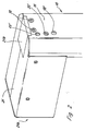
- the drive motor is arranged in a box-like housing whose upper wall or a cover engages over the transmission housing or the guide tube accommodating the transmission.
- a relatively large bearing surface is created for a furniture component to be adjusted, for example a table top.
- the transmission is arranged in the upper end region of the extendable guide tube. The transmission and the drive motor then follow synchronously the movement of the furniture component to be adjusted.
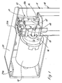
- the electromotive drive 10 includes a vertically movable guide tube 11, the cross section may be arbitrary.
- the electromotive drive includes a connected to the guide tube in a manner explained in more detail drive motor 12 and a fixed in the upper region of the guide tube 11 gear 13, which has a gear housing 13a, which is designed so that it closes in the guide tube 11 and connected thereto , for example screwed.
- the gear 13 is in the illustrated embodiment, a worm gear with a worm 14, which is shown only schematically in the figure 1 and which is in engagement with a rotatably mounted worm wheel 15.
- the worm 14 can be rotatably mounted on the output pin of the drive motor 12 or the output pin could be designed as a worm.
- the worm wheel 15 is rotatably mounted in bearings 16, 17. In unspecified manner, a spindle, not shown, is driven directly or indirectly by the worm wheel 15, whereby the extension of the guide tube 11 is achieved.
- the gear housing 13a is equipped with two through-channels 18, 19 which are superimposed. Through these channels through fastening screws are inserted, which are bolted to the frontal wall of the drive motor 12. As a result, the drive motor 12 is pulled against a surface of the transmission housing 13.
- the gear housing 13 with the screwed-on motor 12 is fastened with at least one surface on the inner contour of the guide tube 11, for example by means of screws 30.
- the guide tube 11 has through holes 18 ', 19', 20 ', through which the fastening screws 18, 19 and the adjusting screw 20 of the motor 12 can be reached.
- the transmission is equipped with a position sensor to detect the respective position of the extendable guide tube 11.
- the drive motor 12 is arranged in a box-like housing 21, which is closed by a cover 21 a in the illustrated embodiment.
- the box-like housing 21 also engages over the guide tube 11 and has in a further ausgestalteter form an opening 21b, which can be closed by a lid and used for assembly and / or maintenance purposes.
- the drive motor 12 is normally a DC motor, which is operated with a safety extra-low voltage.
- the electromotive drive is also equipped with an unspecified control and a manual control device.
- the invention is not limited to the illustrated embodiment. It is essential that an electromotive drive, in particular designed as a lifting drive is provided with a minimum number of components, wherein the transmission 13 has a matched to the inner contour or to a part of the inner contour of the guide tube 11 gear housing 13a.
Landscapes
- Engineering & Computer Science (AREA)
- Power Engineering (AREA)
- Connection Of Motors, Electrical Generators, Mechanical Devices, And The Like (AREA)
- Transmission Devices (AREA)
- Gear Transmission (AREA)
- Power-Operated Mechanisms For Wings (AREA)
Claims (12)
- Commande de meuble (10) à moteur électrique, en particulier commande télescopique avec un moteur d'entraînement (12), une transmission (13) réduisant la vitesse de rotation du moteur et comportant un boîtier de transmission (13a), avec un tube de guidage (11) fixe et au moins un tube de guidage (11) extractible et avec une broche pouvant être entraînée en rotation et s'étendant dans la direction longitudinale des tubes de guidage (11), caractérisée en ce que le boîtier de transmission (1 3a) est disposé dans un tube de guidage (11) de manière à le fermer, et en ce que le moteur d'entraînement (12) est disposé latéralement, à côté du tube de guidage (11) recevant le boîtier de transmission (1 3a).
- Commande de meuble à moteur électrique selon la revendication 1, caractérisée en ce que le bout d'arbre de sortie du moteur d'entraînement (12) est décalé par rapport à l'axe médian longitudinal du tube de guidage (11) correspondant.
- Commande de meuble à moteur électrique selon la revendication 1, caractérisée en ce que la transmission (13) est une transmission à vis sans fin constituée d'une vis sans fin (14) et d'une roue pour vis (15).
- Commande de meuble à moteur électrique selon une ou plusieurs des revendications 1 à 3 précédentes, caractérisée en ce que le moteur d'entraînement (12) est fixé par au moins deux vis de fixation traversant des canaux pour vis (18, 19) du boîtier de transmission (13a), de manière que la face frontale du moteur d'entraînement (12), tournée vers la transmission, soit tirée de préférence contre le boîtier de transmission (13a).
- Commande de meuble à moteur électrique selon une ou plusieurs des revendications 1 à 4 précédentes, caractérisée en ce que la position du moteur d'entraînement (12) par rapport à la transmission (13) est réglable au moyen d'un dispositif d'ajustage.
- Commande de meuble à moteur électrique selon la revendication 5, caractérisée en ce que le dispositif d'ajustage est constitué d'au moins une vis d'ajustage qui s'étend parallèlement et à distance des vis de fixation du moteur d'entraînement (12).
- Commande de meuble à moteur électrique selon une ou plusieurs des revendications 1 à 6 précédentes, caractérisée en ce que le contour extérieur du boîtier de transmission (13a) correspond approximativement au contour intérieur du tube de guidage (11).
- Commande de meuble à moteur électrique selon une ou plusieurs des revendications 1 à 7 précédentes, caractérisée en ce que la roue pour vis (15) comporte un anneau placé solidairement en rotation dessus, qui sert d'émetteur d'impulsions.
- Commande de meuble à moteur électrique selon une ou plusieurs des revendications 1 à 8 précédentes, caractérisée en ce que l'entraînement à moteur électrique (10) est équipé d'un transmetteur de position.
- Commande de meuble à moteur électrique selon une ou plusieurs des revendications 1 à 9 précédentes, caractérisée en ce que le moteur d'entraînement (12) est disposé dans un boîtier (21) de type caisson dont la paroi supérieure ou son couvercle (21 a) passe sur le tube de guidage (11) recevant le boîtier de transmission (13a).
- Commande de meuble à moteur électrique selon une ou plusieurs des revendications 1 à 10 précédentes, caractérisée en ce que la transmission (13) et le moteur d'entraînement (12) sont associés à la zone d'extrémité supérieure d'un tube de guidage (11) extractible.
- Commande de meuble à moteur électrique selon une ou plusieurs des revendications 1 à 11 précédentes, caractérisée en ce que le boîtier de transmission (13a) est fixé au moyen de vis (30) sur le tube de guidage (11).
Applications Claiming Priority (2)
| Application Number | Priority Date | Filing Date | Title |
|---|---|---|---|
| DE20111205U DE20111205U1 (de) | 2001-07-05 | 2001-07-05 | Elektromotorischer Antrieb |
| DE20111205U | 2001-07-05 |
Publications (2)
| Publication Number | Publication Date |
|---|---|
| EP1273247A1 EP1273247A1 (fr) | 2003-01-08 |
| EP1273247B1 true EP1273247B1 (fr) | 2006-08-23 |
Family
ID=7958991
Family Applications (1)
| Application Number | Title | Priority Date | Filing Date |
|---|---|---|---|
| EP20020014826 Expired - Lifetime EP1273247B1 (fr) | 2001-07-05 | 2002-07-03 | Entraînement à moteur électrique |
Country Status (2)
| Country | Link |
|---|---|
| EP (1) | EP1273247B1 (fr) |
| DE (2) | DE20111205U1 (fr) |
Families Citing this family (2)
| Publication number | Priority date | Publication date | Assignee | Title |
|---|---|---|---|---|
| DE102009015690A1 (de) * | 2009-03-31 | 2010-10-07 | Logicdata Electronic & Software Entwicklungs Gmbh | Linearantrieb und Tisch mit Linearantrieb |
| DK2503918T3 (da) * | 2009-11-28 | 2016-09-19 | Linak As | Lineær aktuator |
Family Cites Families (5)
| Publication number | Priority date | Publication date | Assignee | Title |
|---|---|---|---|---|
| CH678174A5 (en) * | 1989-05-12 | 1991-08-15 | Schumo Ag | Hoist with spindle driven by worm gear - has worm, wheel, meshing with drive worm, on tubular worm wheel support with inner spindle extension |
| US5144738A (en) * | 1991-04-29 | 1992-09-08 | Ford Motor Company | Automatic retention adjustment of motor armature assembly |
| US5809833A (en) * | 1996-09-24 | 1998-09-22 | Dana Corporation | Linear actuator |
| DE19743129C2 (de) * | 1997-08-25 | 1999-08-26 | Bosch Gmbh Robert | Kraftfahrzeug-Schließvorrichtung mit einer Positionserkennung eines sich bewegenden Stellelementes |
| DE29919215U1 (de) * | 1999-11-03 | 2000-03-16 | Dewert Antriebs- und Systemtechnik GmbH & Co KG, 32278 Kirchlengern | Teleskopantriebseinheit |
-
2001
- 2001-07-05 DE DE20111205U patent/DE20111205U1/de not_active Expired - Lifetime
-
2002
- 2002-07-03 EP EP20020014826 patent/EP1273247B1/fr not_active Expired - Lifetime
- 2002-07-03 DE DE50207906T patent/DE50207906D1/de not_active Expired - Lifetime
Also Published As
| Publication number | Publication date |
|---|---|
| DE20111205U1 (de) | 2001-08-30 |
| DE50207906D1 (de) | 2006-10-05 |
| EP1273247A1 (fr) | 2003-01-08 |
Similar Documents
| Publication | Publication Date | Title |
|---|---|---|
| DE3318935C1 (de) | Verstellbare Lenkeinrichtung fuer Kraftfahrzeuge | |
| EP3700799B1 (fr) | Colonne de direction pour véhicule automobile | |
| DE3938353A1 (de) | Spindelantriebsvorrichtung zur erzeugung von wahlweisen linear- und/oder drehbewegungen der spindel | |
| EP0279236B1 (fr) | Dispositif d'actionnnement rotatif pour portes pivotantes en particulier pour véhicules | |
| EP0700733A1 (fr) | Dispositif de nettoyage, et/ou d'ébarbage des pièces pour projection d'un liquide sous pression | |
| EP1097657B1 (fr) | Unité téléscopique d'entraínement | |
| EP0581982A1 (fr) | Porte pivotante pour passage de clients | |
| DE19853989C1 (de) | Vorrichtung zum Öffnen und Verschliessen einer Öffnung in einer Wandung mittels einer Schiebetür | |
| EP1273247B1 (fr) | Entraînement à moteur électrique | |
| DE19903718C1 (de) | Linearantrieb mit Gewindespindel | |
| EP1925772B1 (fr) | Unité de détection | |
| EP0752358A1 (fr) | Dispositif de réglage de l'inclinaison d'enveloppe tubulaire, montée de manière pivotante, de l'arbre de direction d'un véhicule automobile | |
| WO2004032684A1 (fr) | Mecanisme de commande a moteur electrique pour meubles | |
| EP1247477B1 (fr) | Mécanisme de commande à moteur électrique | |
| DE19735492A1 (de) | Koaxialtrieb für den Objekttisch eines Mikroskops | |
| EP1584264B1 (fr) | Système d'entrainement réglable en hauteur notamment pour meubles | |
| EP1152167B1 (fr) | Dispositif pour règler la position entre pièces mobiles l'une par rapport à l'autre | |
| EP1201370B1 (fr) | Dispositif de serrage de pièces à usiner à actionnement électrique | |
| DE69314666T2 (de) | Gerät zum automatischen horizontalen anpassen eines sitzes | |
| EP0816281B1 (fr) | Plate-forme de levage pour véhicules | |
| DE19652905C2 (de) | Antrieb für einen Tisch einer an einer Basis befestigten Transport- oder Hubeinrichtung | |
| EP0509362A1 (fr) | Marche pivotante pouvant être mise en connexion avec un moteur rotatif électrique | |
| DE3624974A1 (de) | Antriebseinrichtung fuer einen insbesondere zur aufnahme des greifwerkzeuges eines roboters geeigneten abtriebsflansch | |
| EP0949070B1 (fr) | Palier pour un cylindre dans une machine d'impression | |
| DE202005021004U1 (de) | Höhenverstellbarer Antrieb, insbesondere für Möbel |
Legal Events
| Date | Code | Title | Description |
|---|---|---|---|
| PUAI | Public reference made under article 153(3) epc to a published international application that has entered the european phase |
Free format text: ORIGINAL CODE: 0009012 |
|
| AK | Designated contracting states |
Kind code of ref document: A1 Designated state(s): AT BE BG CH CY CZ DE DK EE ES FI FR GB GR IE IT LI LU MC NL PT SE SK TR |
|
| AX | Request for extension of the european patent |
Free format text: AL;LT;LV;MK;RO;SI |
|
| 17P | Request for examination filed |
Effective date: 20030701 |
|
| AKX | Designation fees paid |
Designated state(s): DE DK FI NL SE |
|
| 17Q | First examination report despatched |
Effective date: 20050215 |
|
| GRAP | Despatch of communication of intention to grant a patent |
Free format text: ORIGINAL CODE: EPIDOSNIGR1 |
|
| GRAS | Grant fee paid |
Free format text: ORIGINAL CODE: EPIDOSNIGR3 |
|
| RAP1 | Party data changed (applicant data changed or rights of an application transferred) |
Owner name: DEWERT ANTRIEBS- UND SYSTEMTECHNIK GMBH |
|
| GRAA | (expected) grant |
Free format text: ORIGINAL CODE: 0009210 |
|
| AK | Designated contracting states |
Kind code of ref document: B1 Designated state(s): DE DK FI NL SE |
|
| PG25 | Lapsed in a contracting state [announced via postgrant information from national office to epo] |
Ref country code: FI Free format text: LAPSE BECAUSE OF FAILURE TO SUBMIT A TRANSLATION OF THE DESCRIPTION OR TO PAY THE FEE WITHIN THE PRESCRIBED TIME-LIMIT Effective date: 20060823 Ref country code: NL Free format text: LAPSE BECAUSE OF FAILURE TO SUBMIT A TRANSLATION OF THE DESCRIPTION OR TO PAY THE FEE WITHIN THE PRESCRIBED TIME-LIMIT Effective date: 20060823 |
|
| REF | Corresponds to: |
Ref document number: 50207906 Country of ref document: DE Date of ref document: 20061005 Kind code of ref document: P |
|
| PG25 | Lapsed in a contracting state [announced via postgrant information from national office to epo] |
Ref country code: SE Free format text: LAPSE BECAUSE OF FAILURE TO SUBMIT A TRANSLATION OF THE DESCRIPTION OR TO PAY THE FEE WITHIN THE PRESCRIBED TIME-LIMIT Effective date: 20061123 Ref country code: DK Free format text: LAPSE BECAUSE OF FAILURE TO SUBMIT A TRANSLATION OF THE DESCRIPTION OR TO PAY THE FEE WITHIN THE PRESCRIBED TIME-LIMIT Effective date: 20061123 |
|
| NLV1 | Nl: lapsed or annulled due to failure to fulfill the requirements of art. 29p and 29m of the patents act | ||
| PLBE | No opposition filed within time limit |
Free format text: ORIGINAL CODE: 0009261 |
|
| STAA | Information on the status of an ep patent application or granted ep patent |
Free format text: STATUS: NO OPPOSITION FILED WITHIN TIME LIMIT |
|
| 26N | No opposition filed |
Effective date: 20070524 |
|
| REG | Reference to a national code |
Ref country code: DE Ref legal event code: R082 Ref document number: 50207906 Country of ref document: DE Representative=s name: PATENT- UND RECHTSANWAELTE LOESENBECK, SPECHT,, DE |
|
| REG | Reference to a national code |
Ref country code: DE Ref legal event code: R082 Ref document number: 50207906 Country of ref document: DE Representative=s name: PATENT- UND RECHTSANWAELTE LOESENBECK, SPECHT,, DE Effective date: 20131004 Ref country code: DE Ref legal event code: R081 Ref document number: 50207906 Country of ref document: DE Owner name: DEWERTOKIN GMBH, DE Free format text: FORMER OWNER: DEWERT ANTRIEBS- UND SYSTEMTECHNIK GMBH, 32278 KIRCHLENGERN, DE Effective date: 20131004 |
|
| PGFP | Annual fee paid to national office [announced via postgrant information from national office to epo] |
Ref country code: DE Payment date: 20180727 Year of fee payment: 17 |
|
| REG | Reference to a national code |
Ref country code: DE Ref legal event code: R119 Ref document number: 50207906 Country of ref document: DE |
|
| PG25 | Lapsed in a contracting state [announced via postgrant information from national office to epo] |
Ref country code: DE Free format text: LAPSE BECAUSE OF NON-PAYMENT OF DUE FEES Effective date: 20200201 |