EP1273751B1 - Cadre pour une porte à un ou plusieurs battants - Google Patents
Cadre pour une porte à un ou plusieurs battants Download PDFInfo
- Publication number
- EP1273751B1 EP1273751B1 EP02014730A EP02014730A EP1273751B1 EP 1273751 B1 EP1273751 B1 EP 1273751B1 EP 02014730 A EP02014730 A EP 02014730A EP 02014730 A EP02014730 A EP 02014730A EP 1273751 B1 EP1273751 B1 EP 1273751B1
- Authority
- EP
- European Patent Office
- Prior art keywords
- frame
- ceiling
- capping beam
- frame according
- door
- Prior art date
- Legal status (The legal status is an assumption and is not a legal conclusion. Google has not performed a legal analysis and makes no representation as to the accuracy of the status listed.)
- Expired - Lifetime
Links
- 238000007789 sealing Methods 0.000 claims description 14
- 239000002023 wood Substances 0.000 claims description 12
- 239000000463 material Substances 0.000 claims description 11
- 238000006073 displacement reaction Methods 0.000 claims description 6
- 239000000779 smoke Substances 0.000 claims description 5
- 238000003780 insertion Methods 0.000 claims description 3
- 230000037431 insertion Effects 0.000 claims description 3
- 230000004888 barrier function Effects 0.000 claims description 2
- 230000000903 blocking effect Effects 0.000 claims 1
- 230000000149 penetrating effect Effects 0.000 claims 1
- 238000009434 installation Methods 0.000 description 8
- 229910000831 Steel Inorganic materials 0.000 description 5
- 239000010959 steel Substances 0.000 description 5
- 239000002184 metal Substances 0.000 description 3
- 238000005096 rolling process Methods 0.000 description 3
- 238000010276 construction Methods 0.000 description 2
- 238000005192 partition Methods 0.000 description 2
- 230000000007 visual effect Effects 0.000 description 2
- 230000002411 adverse Effects 0.000 description 1
- 230000001447 compensatory effect Effects 0.000 description 1
- 239000002131 composite material Substances 0.000 description 1
- 230000001419 dependent effect Effects 0.000 description 1
- 230000001627 detrimental effect Effects 0.000 description 1
- 239000003063 flame retardant Substances 0.000 description 1
- 238000000034 method Methods 0.000 description 1
- 239000000203 mixture Substances 0.000 description 1
- 239000004033 plastic Substances 0.000 description 1
- 230000002265 prevention Effects 0.000 description 1
- 230000005855 radiation Effects 0.000 description 1
- 238000009418 renovation Methods 0.000 description 1
- 239000007787 solid Substances 0.000 description 1
- 238000012549 training Methods 0.000 description 1
- 238000012546 transfer Methods 0.000 description 1
Images

Classifications
-
- E—FIXED CONSTRUCTIONS
- E04—BUILDING
- E04B—GENERAL BUILDING CONSTRUCTIONS; WALLS, e.g. PARTITIONS; ROOFS; FLOORS; CEILINGS; INSULATION OR OTHER PROTECTION OF BUILDINGS
- E04B2/00—Walls, e.g. partitions, for buildings; Wall construction with regard to insulation; Connections specially adapted to walls
- E04B2/74—Removable non-load-bearing partitions; Partitions with a free upper edge
- E04B2/82—Removable non-load-bearing partitions; Partitions with a free upper edge characterised by the manner in which edges are connected to the building; Means therefor; Special details of easily-removable partitions as far as related to the connection with other parts of the building
- E04B2/825—Removable non-load-bearing partitions; Partitions with a free upper edge characterised by the manner in which edges are connected to the building; Means therefor; Special details of easily-removable partitions as far as related to the connection with other parts of the building the connection between the floor and the ceiling being achieved without any restraining forces acting in the plane of the partition
-
- E—FIXED CONSTRUCTIONS
- E06—DOORS, WINDOWS, SHUTTERS, OR ROLLER BLINDS IN GENERAL; LADDERS
- E06B—FIXED OR MOVABLE CLOSURES FOR OPENINGS IN BUILDINGS, VEHICLES, FENCES OR LIKE ENCLOSURES IN GENERAL, e.g. DOORS, WINDOWS, BLINDS, GATES
- E06B1/00—Border constructions of openings in walls, floors, or ceilings; Frames to be rigidly mounted in such openings
- E06B1/02—Base frames, i.e. template frames for openings in walls or the like, provided with means for securing a further rigidly-mounted frame; Special adaptations of frames to be fixed therein
-
- E—FIXED CONSTRUCTIONS
- E06—DOORS, WINDOWS, SHUTTERS, OR ROLLER BLINDS IN GENERAL; LADDERS
- E06B—FIXED OR MOVABLE CLOSURES FOR OPENINGS IN BUILDINGS, VEHICLES, FENCES OR LIKE ENCLOSURES IN GENERAL, e.g. DOORS, WINDOWS, BLINDS, GATES
- E06B1/00—Border constructions of openings in walls, floors, or ceilings; Frames to be rigidly mounted in such openings
- E06B1/56—Fastening frames to the border of openings or to similar contiguous frames
- E06B1/60—Fastening frames to the border of openings or to similar contiguous frames by mechanical means, e.g. anchoring means
- E06B1/6015—Anchoring means
- E06B1/6023—Anchoring means completely hidden between the frame and the border of the opening, at least part of the means being previously fixed to the wall
Definitions
- the invention relates to a frame according to the preamble of the appended claim 1.
- a frame is known from FR-A 2 042 240.
- DE 297 03 434 U1 relates to a mounting device for the upper window frame in prefabricated high-rise buildings. There is usually already on site an angle steel available, which complicates the subsequent installation of conventional window frames. DE 297 03 434 U1 proposes now to use this only especially in prefabricated buildings already existing on site angle steel as a holding part for fixing the window frame.
- the known holding device of the upper Zargenholm is firmly clamped to the angle steel by means of clamping screws.
- the achievable stationary connection is found to be essential.
- the remaining parts are glued.
- DE 198 55 622 A1 relates to a clamp for fixing components to be mounted, in particular a setting clip for setting door frames.
- the setting clip is used as a tool instead of usual wedges and removed after setting the door frame again.
- DE 195 44 719 C1 relates to a mounting device for fastening a window insert in comfortablygauernen soffit frame.
- This mounting device contains pressurized plug-in pins. These bolts are displaceable with respect to the jamb frame acting as a holding part, while the actual window frame spar is held stationary on the jamb frame.
- FR-A-2 042 240 a door frame for a single-leaf door is known.
- the upper Zargenholm is held against a ceiling in the height direction movable on a holding part.
- a plurality of adjusting screws are provided on the holding part, by means of which the Zargenholm is height-adjustable screwed to the holding part.
- the connection of the ceiling-side Zargenholms to the ceiling can cause difficulties when variations, tolerances and deflections occur in the ceiling area, especially with regard to high-rise buildings that perform oscillating compensatory movements under wind pressure, etc., which manifests itself in increasing height with changes in the distance between the ceiling and floor , In these cases, this can be caused by pressure on the frame to corresponding deformations and thus Pinching the closed door leaves or straining the glazing up to damage.
- the invention is therefore based on the object to improve a frame of the type mentioned in the preamble of claim 1 such that the operational readiness and function of built-in with such a frame doors even when installed in high-rise buildings for decades to ensure.
- a ceiling spar with free-swinging compensation can be achieved, which is intended in particular to exclude any subsequent deflections caused by whatever reason, or primarily a compressive load or other load on the connection between the wall-ceiling on the one hand and the door on the other hand.
- a compressive load or other load on the connection between the wall-ceiling on the one hand and the door on the other hand.
- a form-fitting sliding guide device which permits a displacement of the cover-side frame member relative to the ceiling and / or the wall of the room in a height direction and blocks a displacement thereof in a direction perpendicular to this height direction.
- the Zargenholm can therefore move relative to the ceiling to compensate for building fluctuations to some extent in the vertical direction, but not in the direction perpendicular thereto or only to the extent limited extent.
- a good stability and strength of the frame is achieved, which is especially in door frames of heavy special doors (burglary, bulletproof, fire doors, smoke doors, radiation protection doors, ...), where the pivoting movement of very heavy door leaves of the frame and be supported on the wall, is advantageous.
- the holding part of the mounting device formed as part of the frame may comprise a rod extending in the longitudinal direction of the cover side frame beam, in particular in the form of a beam, or a plurality of rod sections arranged successively in this direction, in particular in the form of beam sections, which or relative to the Ceiling remaining fixed at the installation location or can be fastened.
- the holding part can even contribute to the outer visual appearance of the frame and remain uncovered to some extent, without this being unfavorable for the appearance of the door.
- sliding guide means In a height direction extending connectors or running in a vertical direction sliding guide, for example, formed by a means for positively guiding a sliding movement (hereinafter called sliding guide means) may be provided to connect the holding part with the cover side Zargenholm slidably.
- sliding guide device has a male element on the holding part and / or the Zargenholm and a corresponding, correspondingly formed on the Zargenholm and / or the holding part Einsteckaus fundamentalung.
- plug-in connections or similar sliding guides it is possible to allow desired sliding movements for the purpose of tolerance or motion compensation, but to prevent undesired displacements of the frame.
- the slide or the connectors can be equipped with more or less large game, so that the Zargenholm in the height direction according to the guide path is free and displaceable in the vertical direction in the context of the game.
- embodiments are also conceivable and desirable in some installation situations in which a backlash-free and even with (low) frictional resistance clamping guide is provided.
- the frictional resistance of the guides or connectors are always such that building dislocations or building movements are automatically compensated without affecting the frame and / or the door or the function or appearance.
- a (light) terminals or a (light) frictional engagement could be advantageous, for example, during assembly of the upper frame handle for handling it before its final attachment or also with regard to the stability of the frame.
- hybrids for example, such that a sliding guide with little or no resistance in one direction, preferably the height direction, and a sliding guide with greater resistance in another direction is provided.
- a sliding guide roller guides or the like for guiding the two mutually movable sub-elements of the frame are possible.
- the cover side frame spar is composed of a plurality of profiled bars, which are each provided with the flange-like portion for forming the sliding guide means covering frame mirrors.
- plug connections are created by engaging in corresponding insertion plug-in pins.
- the locking pins can be attached by suitable connection methods to one of the mutually movable sub-elements of the frame member.
- metal bolts are provided with heads that engage positively in a cavity in the sub-element and / or clamped with force fit with this sub-element for common movement relative to the other sub-element having the insertion, are braced.
- the holding part has an engagement rail arranged in one or in the longitudinal direction, fixed on the ceiling or to be fixed, which points downwardly into a groove-shaped recess in the upwardly projecting web Surface of the frame spar is used.
- the engagement rail are assigned on both sides parallel strips, between the mutually facing side surfaces and the respective opposite side surfaces of the cover used in the holding position Zargenholms the sealing and / or sliding strips are arranged.
- the strips are to be mounted directly on the ceiling, although an attachment to or integral with the holding part or the engagement rail is conceivable and advantageous.
- the mounting device is a component of a frame of a single or multi-leaf door, in which the door leaf or the door leaves of the door are pivotally held.
- the frame according to the invention has the cover-side Zargenholm, which can be held by the support means at least in the height direction slidably relative to the ceiling.
- the frame may be, for example, a wooden block frame or a wooden frame.
- the frame is designed as part of a fire and / or Rauchschutzab gleiches.
- it is provided with at least one strip of intumescent under heat material.
- the strip is used in case of fire for sealing gaps formed between individual sub-elements of the frame member and / or between a sub-element of the frame and the ceiling or the wall of the room.
- the upper connection of the frame to the ceiling is flexible in terms of materials.
- the holding part which is first attached to the ceiling - and could also be in the form of an angle -, could be made of wood, metal, especially steel or other materials, including composite materials or mixtures of materials, while the Zargenholm and / or the rest of the Frame could also be made of wood, metal or other materials as well as hybrid forms.
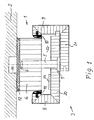
- FIG. 1 a wooden block frame built on the basis of wood materials fire door with smoke protection function
- Fig. 2 a wooden frame of such a door.
- the drawings each show a horizontal section through the extending approximately parallel to the ceiling, ceiling side Zargenholm in its installed position on a holding part also shown cut, which is fixed to the building ceiling.
- Fig. 1 shows a generally designated 1 support means, with the help of the ceiling 2, a total of 3 designated ceiling-side Zargenholm a wood block frame is held.
- a holding part is in the space below the ceiling protruding rod, here in the form of a bar 4, fixed to the ceiling 2 with fastening means not shown.
- the bar 4 extends in the direction of him to be determined, parallel Zargenholmes 3.
- the bar 4 preferably has at least substantially the length of the Zargenholmes 3 on.
- a sliding guide device is provided between the holding part of the holder 1, i. here the beam 4, and the Zargenholm 3 .
- This is formed in the first embodiment by connectors, here in the form of pin 5 and holes 6 as engagement openings for receiving the same.
- the ceiling-side Zargenholm 3 is slidably connected to the beam 4.
- the locking pins 5 are supported by bolt heads 7 on the Zargenholm 3.
- the wooden block frame is equipped with frame mirrors 8 and 9.
- the Zargenholm 3 in several, here two, connected to each other via tongue and groove engagement profile bars 20, 21 divided with L-profile.
- As a flange-like section forms one of the legs of each L-profile
- the frame mirrors 8 and 9 overlap in the installed state between their laterally mutually facing surfaces opposite side surfaces of the beam 4.
- each sealing or sliding strips 10 are arranged, here in such a way that the slide strips are fastened to the frame mirrors 8, 9.
- the determination of the beam 4 on the underside of the ceiling 2 can be done via an insulating intermediate layer 12. Trained as sliding strips sealing strips 10 prevent passage through the formed between the frame beam 3 and the beam 4 gap 22. In particular, the passage of smoke is thereby prevented in case of fire.
- a strip 23 provided from intumescent under heat material to prevent the passage of fire in case of fire.
- Fig. 2 shows a differently constructed mounting device, which is designed for the mounting of a cover-side Zargenholms 13 of a wooden frame.
- the holding device comprises an engagement rail 14 to be fixed on the ceiling side, which extends in the longitudinal direction of the frame member 13 and preferably has approximately its length.
- This engagement rail 14 is fixed in a manner not shown on the lower surface of the ceiling 2 adjacent to this and has a web 15 which engages in a correspondingly extending groove 16 in the ceiling 2 facing the surface of the frame member 13 slidingly slidably, as the Trace drawing.
- a sliding guide device between the Zargenholm 13 and acting here as a holding part engagement rail 14 is provided with the web 15 as a male or male member and the groove 16 as an engagement or Einsteckaus Principleung.
- engagement rail 14 Parallel and on both sides of the engagement rail 14 cover elements in the form of strips 17 and 18 are mounted, in the present case in turn fastened in a manner not shown directly on the underside of the ceiling 2 projecting from this.
- the engagement rail 14 with the strips 17 and 18 may also be integrally formed.
- the strips 17 and 18 are arranged spaced from each other such that their mutually facing side surfaces of the Zargenholm 13 more or less accurately between take up, so that in each case the side surface of one of the strips 17 and 18 with one of the side surfaces of the Zargenholms 13 opposite.
- the inclusion of Zargenholms 13 between the strips 17 and 18 is sealed by mounted in the region of the opposite side surfaces sealing and wear strips 10, which are fixed in the present case in the strips 17 and 18.
- the sealing strips 10 embodied here as sliding strips serve to seal the gap 25 between the ceiling 2 and the displaceably mounted frame rail 13, for example against the passage of smoke in the event of fire.
- the at the ceiling-side bracket at least in the height direction sliding sliding frames are not only independent of the material and the shape, but also suitable for doors of certain tasks such as sound-absorbing, smoke-tight or fire retardant trained door and frame areas.
- the sealing or sliding strips can represent special measures in terms of sealing.
- an upper frame element could be formed by fixed glazings or by inner wall elements.
Landscapes
- Engineering & Computer Science (AREA)
- Civil Engineering (AREA)
- Structural Engineering (AREA)
- Architecture (AREA)
- Mechanical Engineering (AREA)
- Electromagnetism (AREA)
- Physics & Mathematics (AREA)
- Wing Frames And Configurations (AREA)
- Door And Window Frames Mounted To Openings (AREA)
- Special Wing (AREA)
- Housing For Livestock And Birds (AREA)
- Auxiliary Methods And Devices For Loading And Unloading (AREA)
- Supports Or Holders For Household Use (AREA)
- Vehicle Step Arrangements And Article Storage (AREA)
- Support Devices For Sliding Doors (AREA)
Claims (15)
- Dormant d'une porte à un ou plusieurs vantaux pour supporter d'une manière pivotante un ou plusieurs vantaux de la porte, lequel dormant comportant une traverse de dormant (3, 13) s'étendant vers le plafond et un moyen de support (1), la traverse de dormant (3, 13) au côté de plafond pouvant être supportée par rapport à un plafond (2) d'une chambre qui est à munir de la porte d'une manière mobile au moins en la direction verticale par le moyen de support (1), et la traverse de dormant (3, 13) qui s'étend environ parallèlement au plafond (2) étant supportée d'une manière mobile au moins en la direction verticale sur un élément de retenue (4, 14) à un ou plusieurs pièces qui est à fixer sur le plafond et est compris dans le moyen de support (1),
caractérisé en
ce que le moyen de support (1) présente un moyen de guidage à glissement à engagement positif (5, 6; 15, 16) qui permet une déplacement automatique à glissement de la traverse de dormant (3, 13) au côté de plafond par rapport au plafond (2) et/ou le mur de la chambre en une direction verticale et qui limite ou interdit une déplacement du même en une direction perpendiculaire sur cette direction verticale. - Dormant selon la revendication 1,
caractérisé en
ce que l'élément de retenue présente une barre (4), particulièrement en forme d'une poutre (4), s'étendant en la direction longitudinale de la traverse de dormant (3), ou plusieurs sections de barre arrangées d'une manière successive en cette direction, particulièrement en forme de sections de barre fixées ou aptes à être fixées par rapport au plafond (2) et aptes à être reliées à la traverse de dormant (3) au côté de plafond, au moins par le guidage à glissement s'étendant en la direction verticale. - Dormant selon la revendication 2,
caractérisé en
ce qu'il sont disposées des barres d'étanchéité et/ou de glissement (10) entre les faces latéraux de la barre (4) ou des sections de barre et des têtes de dormant (8, 9) de la traverse de dormant (3) au côté de plafond les recouvrant. - Dormant selon l'une des revendications précédentes,
caractérisé en
ce que le moyen de guidage à glissement (5, 6) présente des axes débrochables (5) qui engagent dans des orifices d'enfichage (6) correspondantes. - Dormant selon la revendication 1,
caractérisé en
ce que le moyen de retenue présente une barre d'engagement (14) en une partie ou en plusieurs parties successives en la direction longitudinale, barre qui est fixée ou peut être fixée au plafond (2) et qui peut être mise, avec une âme (15) saillant vers le bas, dans un creux (16) en forme de rainure dans la surface de la traverse de dormant (13) orientée vers le haut, ladite âme (15) et ledit creux (16) formant le moyen de guidage à glissement (15, 16). - Dormant selon la revendication 5,
caractérisé en
ce qu'il sont attribués à la barre d'engagement (14), des deux côtés, des baguettes (17, 18) s'étendant d'une manière parallèle, et qu'entre les faces latéraux tournées l'une vers l'autre et les faces latéraux respectivement opposées de la traverse de dormant (13) au côté de plafond mise dans la position de support sont arrangées des barres d'étanchéité et/ou à glissement (10). - Dormant selon la revendication 6,
caractérisé en
ce que les baguettes (17, 18) sont à monter directement au plafond (2). - Dormant selon l'une des revendications précédentes,
caractérisé en
ce que le dormant est un dormant en charpente ou une traverse dormante. - Dormant selon l'une des revendications précédentes,
caractérisé en
ce qu'il présente un élément de recouvrement (8, 9; 17, 18) pour recouvrir le moyen de guidage à glissement (5, 6; 15, 16). - Dormant selon la revendication 9,
caractérisé en
ce que l'élément de recouvrement (8, 9) est formé sur ou comme une partie de la traverse de dormant (3) qui est supportée d'une manière mobile. - Dormant selon la revendication 10,
caractérisé en
ce que l'élément de recouvrement est formé comme un tronçon de type de bride (8, 9) de la traverse de dormant (3) supportée d'une manière mobile. - Dormant selon la revendication 10,
caractérisé en
ce que l'élément de recouvrement est formé comme une baguette (17, 18) qui est à monter fixe ou d'une manière à former une pièce avec l'élément de retenue. - Dormant selon la revendication 11,
caractérisé en
ce que la traverse de dormant (3) au côté de plafond est composée de plusieurs bâtons profilés (20, 21) respectivement munis dudit tronçon de type de bride, pour former des têtes de dormant (8, 9) qui recouvrent le moyen de guidage à glissement (5, 6). - Dormant selon l'une des revendications précédentes,
caractérisé en
ce qu'il est formé comme une partie d'une fermeture coupe-feu et est muni d'au moins une bande (23, 26) d'un matériau moussant sous l'influence de chaleur, pour rendre étanche une fente (22, 25) formée entre les sections individuelles (3, 4, 13, 14) du dormant ou/et entre une section (17, 18, 13) du dormant et le plafond (2), contre le passage de fumée ou feu en cas d'incendie. - Dormant selon la revendication 14,
caractérisé en
ce qu'une fente (22, 25), qui est formée entre le plafond (2) ou l'élément de retenue et la traverse de dormant (3) au côté de plafond pour rendre possible le déplacement à glissement vertical, peut être obturée au moyen d'un matériau moussant sous l'influence de chaleur.
Priority Applications (1)
| Application Number | Priority Date | Filing Date | Title |
|---|---|---|---|
| DE50210187.3T DE50210187C5 (de) | 2001-07-06 | 2002-07-03 | Zarge für eine ein- oder mehrflügelige Tür |
Applications Claiming Priority (2)
| Application Number | Priority Date | Filing Date | Title |
|---|---|---|---|
| DE20111249U | 2001-07-06 | ||
| DE20111249U DE20111249U1 (de) | 2001-07-06 | 2001-07-06 | Halterungseinrichtung für deckenseitigen Zargenholm |
Publications (2)
| Publication Number | Publication Date |
|---|---|
| EP1273751A1 EP1273751A1 (fr) | 2003-01-08 |
| EP1273751B1 true EP1273751B1 (fr) | 2007-05-23 |
Family
ID=7959015
Family Applications (1)
| Application Number | Title | Priority Date | Filing Date |
|---|---|---|---|
| EP02014730A Expired - Lifetime EP1273751B1 (fr) | 2001-07-06 | 2002-07-03 | Cadre pour une porte à un ou plusieurs battants |
Country Status (3)
| Country | Link |
|---|---|
| EP (1) | EP1273751B1 (fr) |
| AT (1) | ATE363014T1 (fr) |
| DE (2) | DE20111249U1 (fr) |
Families Citing this family (1)
| Publication number | Priority date | Publication date | Assignee | Title |
|---|---|---|---|---|
| DE102017000364A1 (de) * | 2017-01-12 | 2018-07-12 | Herport Innenausbauelemente Gmbh & Co. Kg | Vorrichtung zur Aufteilung von Räumen |
Family Cites Families (10)
| Publication number | Priority date | Publication date | Assignee | Title |
|---|---|---|---|---|
| US2054189A (en) * | 1932-12-28 | 1936-09-15 | Bemis Ind Inc | Building construction |
| FR2042240A5 (fr) * | 1970-03-11 | 1971-02-05 | Bois Moules Ste Indle | |
| DE2439979A1 (de) * | 1974-08-21 | 1976-06-16 | Reinhold Michel | Trennwand |
| DE8708829U1 (de) * | 1987-06-25 | 1988-04-28 | Hofer, Rudolf, 8089 Emmering | Montageflansch mit der dazugehörigen Schraube, zur Montage von Fenstern und Türen im Bereich der Altbausanierung |
| CH675613A5 (fr) * | 1988-05-11 | 1990-10-15 | Walter Eisenring | |
| US5228254A (en) * | 1991-01-18 | 1993-07-20 | Plascore, Inc. | Wall system |
| DE4311793A1 (de) * | 1993-04-09 | 1994-10-13 | Rolf Haebe | Befestigungselement |
| DE19544719C1 (de) * | 1995-11-30 | 1996-11-28 | Ahlmann Aco Severin | Einrichtung zum Befestigen eines Fenstereinsatzes |
| DE29703434U1 (de) * | 1997-02-26 | 1997-04-17 | Glusa, Dieter, 06463 Meisdorf | Oberes Befestigungs- und Verleistungssystem für Fenster in Wohnhochhäusern in Plattenbauweise |
| DE19855622C2 (de) * | 1998-12-02 | 2001-10-18 | Peter Richter | Setzklammer |
-
2001
- 2001-07-06 DE DE20111249U patent/DE20111249U1/de not_active Expired - Lifetime
-
2002
- 2002-07-03 AT AT02014730T patent/ATE363014T1/de not_active IP Right Cessation
- 2002-07-03 DE DE50210187.3T patent/DE50210187C5/de not_active Expired - Lifetime
- 2002-07-03 EP EP02014730A patent/EP1273751B1/fr not_active Expired - Lifetime
Also Published As
| Publication number | Publication date |
|---|---|
| EP1273751A1 (fr) | 2003-01-08 |
| DE50210187D1 (de) | 2007-07-05 |
| DE20111249U1 (de) | 2002-11-14 |
| ATE363014T1 (de) | 2007-06-15 |
| DE50210187C5 (de) | 2017-04-13 |
Similar Documents
| Publication | Publication Date | Title |
|---|---|---|
| DE3009729C2 (de) | Feuerhemmender Bauteil | |
| EP3080375A2 (fr) | Dispositif destiné à fermer une ouverture dans un bâtiment | |
| EP3423658B1 (fr) | Porte, fenêtre ou élément de façade | |
| DE8702660U1 (de) | Fenster- oder Tür-Konstruktion mit einem bewegbar gehaltenen, verriegelbaren Flügel | |
| EP2317054A2 (fr) | Porte coulissante | |
| EP2348185A2 (fr) | Vantail pour une porte coulissante coupe-feu dotée d'une poterne et son procédé de fabrication | |
| DE102015107324B4 (de) | Profilschienensystem für den Einbau von Schiebetüren in Hohlwände | |
| DE19744832C2 (de) | Anordnung für den Einbau eines Fensterrahmens | |
| EP1273751B1 (fr) | Cadre pour une porte à un ou plusieurs battants | |
| EP3889384A1 (fr) | Profilé extrudé de section creuse de fenêtre ou de porte, système doté d'un tel profilé de section creuse et cadre fabriqué à partir de celui-ci | |
| EP3480407B1 (fr) | Élément coulissant vertical | |
| CH700077A2 (de) | Türe mit Hohlprofilen und Zarge mit Hohlprofilen. | |
| EP1666691B1 (fr) | Vantail de porte munie d'un dispositif de réglage de hauteur | |
| AT501873A1 (de) | Profil und verfahren zu dessen herstellung | |
| EP3816383B1 (fr) | Agencement de porte coulissante | |
| DE102009022827B4 (de) | Brandschutz- und/oder Rauchschutzschiebetür | |
| DE102017118275B4 (de) | Torvorrichtung und diese enthaltende Toranordnung | |
| DE102016111410A1 (de) | Mittelstütze für eine Gebäudeöffnung mit großer lichter Breite | |
| DE2404526C2 (de) | Verbindungselement zur Befestigung von Wandelementen | |
| CH644667A5 (en) | Casing with window and/or door arranged in brickwork | |
| DE2111268A1 (de) | Feuchtraum-Stell- oder Trennwandsystem | |
| EP3207958A1 (fr) | Guidage latéral pour une fermeture coupe-feu et fermeture coupe-feu équipée de guidage latéraux | |
| EP3674508B1 (fr) | Élément d'insertion, installation de porte pourvue d'élément d'insertion et procédé de montage d'un élément d'insertion | |
| DE2626613A1 (de) | Hebeschiebefluegel, insbesondere fuer fenster | |
| DE29610889U1 (de) | Sektionaltor |
Legal Events
| Date | Code | Title | Description |
|---|---|---|---|
| PUAI | Public reference made under article 153(3) epc to a published international application that has entered the european phase |
Free format text: ORIGINAL CODE: 0009012 |
|
| AK | Designated contracting states |
Kind code of ref document: A1 Designated state(s): AT BE BG CH CY CZ DE DK EE ES FI FR GB GR IE IT LI LU MC NL PT SE SK TR |
|
| AX | Request for extension of the european patent |
Free format text: AL;LT;LV;MK;RO;SI |
|
| 17P | Request for examination filed |
Effective date: 20030314 |
|
| AKX | Designation fees paid |
Designated state(s): AT CH DE LI |
|
| 17Q | First examination report despatched |
Effective date: 20040924 |
|
| RTI1 | Title (correction) |
Free format text: FRAME FOR A SINGLE OR MULTIPLE LEAVED DOOR |
|
| GRAP | Despatch of communication of intention to grant a patent |
Free format text: ORIGINAL CODE: EPIDOSNIGR1 |
|
| GRAS | Grant fee paid |
Free format text: ORIGINAL CODE: EPIDOSNIGR3 |
|
| GRAA | (expected) grant |
Free format text: ORIGINAL CODE: 0009210 |
|
| AK | Designated contracting states |
Kind code of ref document: B1 Designated state(s): AT CH DE LI |
|
| REG | Reference to a national code |
Ref country code: CH Ref legal event code: EP |
|
| REF | Corresponds to: |
Ref document number: 50210187 Country of ref document: DE Date of ref document: 20070705 Kind code of ref document: P |
|
| REG | Reference to a national code |
Ref country code: CH Ref legal event code: NV Representative=s name: BRAUNPAT BRAUN EDER AG |
|
| PLBE | No opposition filed within time limit |
Free format text: ORIGINAL CODE: 0009261 |
|
| STAA | Information on the status of an ep patent application or granted ep patent |
Free format text: STATUS: NO OPPOSITION FILED WITHIN TIME LIMIT |
|
| 26N | No opposition filed |
Effective date: 20080226 |
|
| PGFP | Annual fee paid to national office [announced via postgrant information from national office to epo] |
Ref country code: AT Payment date: 20090714 Year of fee payment: 8 Ref country code: CH Payment date: 20090731 Year of fee payment: 8 |
|
| REG | Reference to a national code |
Ref country code: CH Ref legal event code: PL |
|
| PG25 | Lapsed in a contracting state [announced via postgrant information from national office to epo] |
Ref country code: LI Free format text: LAPSE BECAUSE OF NON-PAYMENT OF DUE FEES Effective date: 20100731 Ref country code: CH Free format text: LAPSE BECAUSE OF NON-PAYMENT OF DUE FEES Effective date: 20100731 |
|
| PG25 | Lapsed in a contracting state [announced via postgrant information from national office to epo] |
Ref country code: AT Free format text: LAPSE BECAUSE OF NON-PAYMENT OF DUE FEES Effective date: 20100703 |
|
| REG | Reference to a national code |
Ref country code: DE Ref legal event code: R043 Ref document number: 50210187 Country of ref document: DE Effective date: 20120521 |
|
| REG | Reference to a national code |
Ref country code: DE Ref legal event code: R206 Ref document number: 50210187 Country of ref document: DE |
|
| PGFP | Annual fee paid to national office [announced via postgrant information from national office to epo] |
Ref country code: DE Payment date: 20200723 Year of fee payment: 19 |
|
| REG | Reference to a national code |
Ref country code: DE Ref legal event code: R119 Ref document number: 50210187 Country of ref document: DE |
|
| PG25 | Lapsed in a contracting state [announced via postgrant information from national office to epo] |
Ref country code: DE Free format text: LAPSE BECAUSE OF NON-PAYMENT OF DUE FEES Effective date: 20220201 |