EP1273780A2 - Procédé de commande d'un moteur à combustion en particulier d'une automobile - Google Patents
Procédé de commande d'un moteur à combustion en particulier d'une automobile Download PDFInfo
- Publication number
- EP1273780A2 EP1273780A2 EP02012228A EP02012228A EP1273780A2 EP 1273780 A2 EP1273780 A2 EP 1273780A2 EP 02012228 A EP02012228 A EP 02012228A EP 02012228 A EP02012228 A EP 02012228A EP 1273780 A2 EP1273780 A2 EP 1273780A2
- Authority
- EP
- European Patent Office
- Prior art keywords
- pressure
- internal combustion
- combustion engine
- fuel
- accumulator
- Prior art date
- Legal status (The legal status is an assumption and is not a legal conclusion. Google has not performed a legal analysis and makes no representation as to the accuracy of the status listed.)
- Granted
Links
Images


Classifications
-
- F—MECHANICAL ENGINEERING; LIGHTING; HEATING; WEAPONS; BLASTING
- F02—COMBUSTION ENGINES; HOT-GAS OR COMBUSTION-PRODUCT ENGINE PLANTS
- F02D—CONTROLLING COMBUSTION ENGINES
- F02D41/00—Electrical control of supply of combustible mixture or its constituents
- F02D41/30—Controlling fuel injection
- F02D41/38—Controlling fuel injection of the high pressure type
- F02D41/3809—Common rail control systems
- F02D41/3836—Controlling the fuel pressure
- F02D41/3863—Controlling the fuel pressure by controlling the flow out of the common rail, e.g. using pressure relief valves
-
- F—MECHANICAL ENGINEERING; LIGHTING; HEATING; WEAPONS; BLASTING
- F02—COMBUSTION ENGINES; HOT-GAS OR COMBUSTION-PRODUCT ENGINE PLANTS
- F02D—CONTROLLING COMBUSTION ENGINES
- F02D41/00—Electrical control of supply of combustible mixture or its constituents
- F02D41/02—Circuit arrangements for generating control signals
- F02D41/04—Introducing corrections for particular operating conditions
- F02D41/12—Introducing corrections for particular operating conditions for deceleration
- F02D41/123—Introducing corrections for particular operating conditions for deceleration the fuel injection being cut-off
-
- F—MECHANICAL ENGINEERING; LIGHTING; HEATING; WEAPONS; BLASTING
- F02—COMBUSTION ENGINES; HOT-GAS OR COMBUSTION-PRODUCT ENGINE PLANTS
- F02D—CONTROLLING COMBUSTION ENGINES
- F02D41/00—Electrical control of supply of combustible mixture or its constituents
- F02D41/30—Controlling fuel injection
- F02D41/38—Controlling fuel injection of the high pressure type
- F02D2041/389—Controlling fuel injection of the high pressure type for injecting directly into the cylinder
-
- F—MECHANICAL ENGINEERING; LIGHTING; HEATING; WEAPONS; BLASTING
- F02—COMBUSTION ENGINES; HOT-GAS OR COMBUSTION-PRODUCT ENGINE PLANTS
- F02D—CONTROLLING COMBUSTION ENGINES
- F02D2200/00—Input parameters for engine control
- F02D2200/02—Input parameters for engine control the parameters being related to the engine
- F02D2200/06—Fuel or fuel supply system parameters
- F02D2200/0602—Fuel pressure
-
- F—MECHANICAL ENGINEERING; LIGHTING; HEATING; WEAPONS; BLASTING
- F02—COMBUSTION ENGINES; HOT-GAS OR COMBUSTION-PRODUCT ENGINE PLANTS
- F02D—CONTROLLING COMBUSTION ENGINES
- F02D2250/00—Engine control related to specific problems or objectives
- F02D2250/31—Control of the fuel pressure
-
- F—MECHANICAL ENGINEERING; LIGHTING; HEATING; WEAPONS; BLASTING
- F02—COMBUSTION ENGINES; HOT-GAS OR COMBUSTION-PRODUCT ENGINE PLANTS
- F02D—CONTROLLING COMBUSTION ENGINES
- F02D41/00—Electrical control of supply of combustible mixture or its constituents
- F02D41/30—Controlling fuel injection
- F02D41/38—Controlling fuel injection of the high pressure type
- F02D41/3809—Common rail control systems
- F02D41/3836—Controlling the fuel pressure
- F02D41/3845—Controlling the fuel pressure by controlling the flow into the common rail, e.g. the amount of fuel pumped
Definitions
- The. invention is based on a method for operating an internal combustion engine, in particular of a motor vehicle, at the fuel from a high pressure pump in one Accumulator is promoted, in which the fuel over an injection valve in a combustion chamber of Internal combustion engine is injected, wherein the pressure in the accumulator to a target pressure plus one Offsetwerts is limited, and in one Sliding operation of the internal combustion engine no fuel over the injection valve is injected. Furthermore
- the invention relates to an internal combustion engine and a control unit for an internal combustion engine of the corresponding type.
- the object of the invention is a method for operating an internal combustion engine, in particular of a motor vehicle in which the fastest possible pressure reduction in the Transition to the push mode is possible.
- This task is used in a method of the beginning mentioned type according to the invention achieved in that Shift operation of the offset value to a minimum value or even set to zero.
- Shift operation of the offset value to a minimum value or even set to zero is the Task solved according to the invention accordingly.
- the shift operation is by a Comparison of the current volume flow through the High pressure pump and the volume flow at zero delivery recognized.
- the inventive method in the form of a Computer program for a control unit Internal combustion engine, in particular of a motor vehicle is provided.
- the computer program has program code on which is suitable, the inventive method when running on a computer.
- the program code can be on a computer readable Be stored on a disk, for example on a so-called flash memory.
- the Invention realized by the computer program, so that this computer program in the same way the invention represents as the procedure for the execution of the Computer program is suitable.
- a fuel supply system 10 is a Internal combustion engine shown.
- the Fuel supply system 10 is also commonly referred to as Common rail system designates and is to direct Injecting fuel into the combustion chambers of the Internal combustion engine suitable under high pressure.
- the fuel is from a fuel tank 11 via a first filter 12 sucked by a prefeed pump 13. at the prefeed pump 13 may be, for example. To a act electric fuel pump.
- the sucked by the feed pump 13 fuel is via a second filter 13- to a metering unit 15 promoted.
- a metering unit 15 may, for example.
- the metering unit 15 is a high-pressure pump 16 downstream.
- the high-pressure pump 16 are usually mechanical pumps used by the Internal combustion engine are driven.
- the high pressure pump 16 is connected to a pressure accumulator 17th which is often referred to as a rail.
- This Accumulator 17 is connected via fuel lines Injectors 21 in contact. About the injectors 21, the fuel is in the combustion chambers of the Internal combustion engine injected.
- a pressure control valve 18th connected to the output side with the fuel tank 11 is coupled.
- the pressure control valve 18 may be For example, to act an electrically controllable solenoid valve.
- a pressure sensor 19 may be provided which with the pressure accumulator 17 is coupled.
- a control device 20 is provided, which of a plurality is acted upon by input signals.
- Input signals may be the speed N of the Internal combustion engine or the engine temperature T the Internal combustion engine act. Also it can be-while act the pressure within the fuel reservoir 17, the is measured by the pressure sensor 19.
- Control unit 20 a plurality of output signals.
- the fuel supply system 10 shown in FIG. 1 is shown works as follows:
- the fuel that is in the fuel tank 11, is sucked by the feed pump 13 and the Metering unit 15 promoted.
- the pressure in this area of the Fuel supply system 10 is usually located in a range of about 1 bar to about 3 bar. This area is therefore also referred to as low pressure range. Of the The aforementioned area can be used with the help of another, in 1 not shown valve monitored or controlled and / or regulated.
- the metering unit 15 From the metering unit 15 is that amount of fuel passed to the high-pressure pump 16, the - due to the each current operating state of the Internal combustion engine - via the injectors 21 in the Combustion chambers of the internal combustion engine to be injected.
- the metering unit 15 of the high-pressure pump 16 supplied amount of fuel is doing as flow designated.
- Fuel in the fuel reservoir 17 is promoted to from there via the injectors 21 in the respective Be injected combustion chambers of the internal combustion engine.
- the supplied from the injectors 21 to the combustion chambers Fuel quantity is referred to as injection quantity.
- the pressure regulating valve 18 to Pressure limit used. This means that Pressure control valve 18 is driven so that it at a predetermined pressure in the pressure accumulator 17 opens. In this way, a pressure increase of the pressure in the Pressure accumulator 17 prevents the predetermined value.
- the Metering unit 15 is driven in such a way that a so-called full promotion takes place. This means, that the high pressure pump 16 is the maximum Fuel amount in the fuel tank 17 promotes.
- the pressure regulating valve 18 also becomes used for pressure limiting.
- the Pressure control valve 18 is driven so that it only at a predetermined value of the pressure in the pressure accumulator 17th opens. It is necessary that the Pressure control valve 18 until reaching the intended Value at which the pressure regulating valve 18 should open, sure remains closed. This default value therefore becomes usually from the target pressure in the pressure accumulator 17th derived with the addition of an offset value. Is that the Target pressure, for example 1600 bar, so is the additive to be added offset value about 250 bar.
- Push mode - the Internal combustion engine before. In this shift operation is no Fuel in the combustion chambers of the internal combustion engine injected. Instead, the internal combustion engine of pushed the downhill rolling motor vehicle and thus in Operation held.
- FIG. 2 shows operating variables of the internal combustion engine plotted against the time t, namely at their transition into the push operation.
- the flow rate of Metering unit 15 is identified by the reference numeral 25, the injection amount of the injectors 21 with the Reference numeral 26, the target pressure in the pressure accumulator 17 with the reference numeral 27, the offset value by the reference numeral 28, the actual pressure in the accumulator 17 without the present invention with the reference numeral 29 and the Ist horr in the pressure accumulator 17 with the present Invention with the reference numeral 30.
- the transition has in the Sliding operation an immediate transfer of the flow rate 25 and the injection amount 26 to zero. immediate This transition then follows according to FIG. 2 time range indicated by the reference numeral 31 and in which the flow rate 25 and the Injection amount 26 remain at zero.
- Control unit 20 and the target pressure 27 for the accumulator 17 reduced according to the figure 2. Because in the shift operation no injection of fuel via the injectors 21 takes place, the pressure reduction of the actual pressure 29 in the Pressure accumulator 17 only via the pressure control valve 18 and over Leaks of components take place.
- the pressure regulating valve 18 opens - without application of the invention - but only when the actual pressure 29 is greater by the offset value 28 than the Target pressure 27. This means that - without application of the Invention - the actual pressure 29 in the time range 31 always is significantly greater than the setpoint pressure 27. This means at the same time that - without application of the invention - for the pressure reduction time required is relatively large.
- the shift operation is recognized by the invention.
- the offset value of the Invention set to a minimum value or even zero.
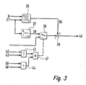
- FIG. 3 shows a method with which the above-described operation of the Internal combustion engine can be performed. This Method is by the controller 20 by software realized.
- the speed N of the internal combustion engine and of the Control unit 20 determined and predetermined target pressure 27 in the pressure accumulator 17 are a pilot control map 35th fed, depending on these operating variables generates a pilot control quantity 36.
- the target pressure 27 is also an offset characteristic 37 which, depending on this, has the offset value 28 certainly.
- a switch 38 and an addition 39 is then the offset value 28 to the pilot size 36 added.
- a control variable 40 for the pressure regulating valve 18, to the the pressure regulating valve 18 is adjusted, and the pressure determines, in which the pressure regulating valve 18 opens.
- a block 44 is checked, whether the pressure 45 in the accumulator 17 is a minimum value Exceeds 46.
- the of the Pressure sensor 19 measured current pressure with the predetermined minimum value 46 compared.
- the minimum value 46 is also given by way of example in FIG.
- Block 44 is achieved in this way that the following explained switching of the offset value takes place only when the current pressure 45 in the accumulator 17 is greater is the minimum value 46.
- the output signals of the blocks 41 and 44 become an AND operation 47 fed, which - if the current Volume flow 42 through the high-pressure pump 16 is smaller or is equal to the flow 43 at zero flow, and provided that the current pressure 45 in the accumulator 17 is greater is switched as the minimum value 46 - the switch 38.
Landscapes
- Engineering & Computer Science (AREA)
- Chemical & Material Sciences (AREA)
- Combustion & Propulsion (AREA)
- Mechanical Engineering (AREA)
- General Engineering & Computer Science (AREA)
- Fuel-Injection Apparatus (AREA)
- Electrical Control Of Air Or Fuel Supplied To Internal-Combustion Engine (AREA)
- Combined Controls Of Internal Combustion Engines (AREA)
- Control Of Vehicle Engines Or Engines For Specific Uses (AREA)
Applications Claiming Priority (2)
| Application Number | Priority Date | Filing Date | Title |
|---|---|---|---|
| DE2001131506 DE10131506A1 (de) | 2001-07-02 | 2001-07-02 | Verfahren zum Betreiben einer Brennkraftmaschine insbesondere eines Kraftfahrzeugs |
| DE10131506 | 2001-07-02 |
Publications (3)
| Publication Number | Publication Date |
|---|---|
| EP1273780A2 true EP1273780A2 (fr) | 2003-01-08 |
| EP1273780A3 EP1273780A3 (fr) | 2005-01-05 |
| EP1273780B1 EP1273780B1 (fr) | 2007-03-28 |
Family
ID=7689985
Family Applications (1)
| Application Number | Title | Priority Date | Filing Date |
|---|---|---|---|
| EP20020012228 Expired - Lifetime EP1273780B1 (fr) | 2001-07-02 | 2002-06-04 | Procédé de commande d'un moteur à combustion en particulier d'une automobile |
Country Status (3)
| Country | Link |
|---|---|
| EP (1) | EP1273780B1 (fr) |
| JP (1) | JP4262451B2 (fr) |
| DE (2) | DE10131506A1 (fr) |
Cited By (3)
| Publication number | Priority date | Publication date | Assignee | Title |
|---|---|---|---|---|
| WO2004061285A1 (fr) * | 2002-12-31 | 2004-07-22 | Robert Bosch Gmbh | Procede pour commander une soupape de regulation de pression dans un systeme d'injection de carburant d'un moteur a combustion interne |
| WO2004104397A1 (fr) * | 2003-05-26 | 2004-12-02 | Siemens Aktiengesellschaft | Procede pour faire fonctionner un moteur a combustion, systeme d'alimentation en carburant et soupape de regulation de debit volumetrique |
| WO2012062522A3 (fr) * | 2010-11-11 | 2012-07-05 | Robert Bosch Gmbh | Procédé pour l'utilisation d'un moteur à combustion interne |
Families Citing this family (4)
| Publication number | Priority date | Publication date | Assignee | Title |
|---|---|---|---|---|
| DE102007017649A1 (de) | 2007-04-12 | 2008-10-16 | Vistec Semiconductor Systems Gmbh | Verfahren zum Bestimmen der Fokuslage von mindestens zwei Kanten von Strukturen auf einem Substrat |
| DE102007023898A1 (de) * | 2007-05-23 | 2008-11-27 | Robert Bosch Gmbh | Verfahren zum Ansteuern eines Einspritzventils |
| DE102010012152A1 (de) | 2010-03-20 | 2011-09-22 | Audi Ag | Verfahren zum Betreiben eines Kraftstoffversorgungssystems |
| DE102014209540A1 (de) | 2014-05-20 | 2015-11-26 | Robert Bosch Gmbh | Verfahren zur Reduzierung eines Drucks in einem Hochdruckspeicher einer Brennkraftmaschine |
Family Cites Families (7)
| Publication number | Priority date | Publication date | Assignee | Title |
|---|---|---|---|---|
| JP2964665B2 (ja) * | 1991-02-27 | 1999-10-18 | 株式会社デンソー | ディーゼル機関の蓄圧式燃料噴射装置 |
| DE19626689C1 (de) * | 1996-07-03 | 1997-11-20 | Bosch Gmbh Robert | Verfahren und Vorrichtung zur Überwachung eines Einspritzsystems |
| JP3713918B2 (ja) * | 1997-08-29 | 2005-11-09 | いすゞ自動車株式会社 | エンジンの燃料噴射方法及びその装置 |
| DE19738502A1 (de) * | 1997-09-03 | 1999-03-04 | Bosch Gmbh Robert | System zur Hochdruckerzeugung |
| JP2000073815A (ja) * | 1998-08-27 | 2000-03-07 | Toyota Motor Corp | 燃料噴射制御装置 |
| DE10003906A1 (de) * | 2000-01-29 | 2001-08-09 | Bosch Gmbh Robert | Verfahren und Vorrichtung zum Kalibrieren eines Drucksensors |
| DE10020629A1 (de) * | 2000-04-27 | 2001-11-08 | Bosch Gmbh Robert | Verfahren zum Betreiben eines Kraftstoffversorgungssystems für eine Brennkraftmaschine insbesondere eines Kraftfahrzeugs |
-
2001
- 2001-07-02 DE DE2001131506 patent/DE10131506A1/de not_active Ceased
-
2002
- 2002-06-04 EP EP20020012228 patent/EP1273780B1/fr not_active Expired - Lifetime
- 2002-06-04 DE DE50209819T patent/DE50209819D1/de not_active Expired - Lifetime
- 2002-07-01 JP JP2002191851A patent/JP4262451B2/ja not_active Expired - Fee Related
Cited By (7)
| Publication number | Priority date | Publication date | Assignee | Title |
|---|---|---|---|---|
| WO2004061285A1 (fr) * | 2002-12-31 | 2004-07-22 | Robert Bosch Gmbh | Procede pour commander une soupape de regulation de pression dans un systeme d'injection de carburant d'un moteur a combustion interne |
| WO2004104397A1 (fr) * | 2003-05-26 | 2004-12-02 | Siemens Aktiengesellschaft | Procede pour faire fonctionner un moteur a combustion, systeme d'alimentation en carburant et soupape de regulation de debit volumetrique |
| US7302935B2 (en) | 2003-05-26 | 2007-12-04 | Siemens Aktiengesellschaft | Method for operating an internal combustion engine, fuel system, and volume flow control valve |
| WO2012062522A3 (fr) * | 2010-11-11 | 2012-07-05 | Robert Bosch Gmbh | Procédé pour l'utilisation d'un moteur à combustion interne |
| CN103221667A (zh) * | 2010-11-11 | 2013-07-24 | 罗伯特·博世有限公司 | 用于控制内燃机的燃油压力的方法 |
| US9249753B2 (en) | 2010-11-11 | 2016-02-02 | Robert Bosch Gmbh | Method for operating an internal combustion engine |
| CN103221667B (zh) * | 2010-11-11 | 2016-05-18 | 罗伯特·博世有限公司 | 用于控制内燃机的燃油压力的方法 |
Also Published As
| Publication number | Publication date |
|---|---|
| EP1273780B1 (fr) | 2007-03-28 |
| EP1273780A3 (fr) | 2005-01-05 |
| DE10131506A1 (de) | 2003-01-23 |
| JP4262451B2 (ja) | 2009-05-13 |
| JP2003056384A (ja) | 2003-02-26 |
| DE50209819D1 (de) | 2007-05-10 |
Similar Documents
| Publication | Publication Date | Title |
|---|---|---|
| DE10296833B4 (de) | Verfahren zur Steuerung des Betriebs einer Kraftstoffeinspritzvorrichtung und Vorrichtung zur Kraftstoffeinspritzung | |
| DE10158950C2 (de) | Verfahren, Computerprogramm, Steuer- und Regelgerät zum Betreiben einer Brennkraftmaschine, sowie Brennkraftmaschine | |
| WO2000031398A1 (fr) | Procede pour faire fonctionner un moteur a combustion interne, notamment d'un vehicule automobile | |
| DE102010000221A1 (de) | Druck-Akkumulations-Kraftstoffeinspritzvorrichtung | |
| EP1348072B1 (fr) | Procede, programme informatique et appareil de commande et/ou de reglage permettant d'exploiter un moteur a combustion interne et moteur a combustion interne | |
| DE102011089254B4 (de) | Verfahren und Vorrichtung zum Steuern der Kraftstoffzufuhr einer mit Flüssiggas betriebenen Verbrennungskraftmaschine | |
| DE10148222A1 (de) | Verfahren zum Betrieb einer Brennkraftmaschine | |
| DE102010028910A1 (de) | Verfahren zum Bereitstellen eines für ein Wiederanlassen einer Common-Rail-Brennkraftmaschine ausreichenden Raildrucks | |
| DE10131507C2 (de) | Verfahren zum Betreiben einer Brennkraftmaschine insbesondere eines Kraftfahrzeugs | |
| EP1090221A1 (fr) | Procede de fonctionnement d'un moteur a combustion interne, notamment pour un vehicule automobile | |
| DE10131783B4 (de) | Verfahren zum Betrieb einer Brennkraftmaschine | |
| EP1273780B1 (fr) | Procédé de commande d'un moteur à combustion en particulier d'une automobile | |
| WO2012028370A1 (fr) | Dispositif de refoulement d'un système d'alimentation en carburant d'un moteur à combustion interne | |
| WO2016005487A1 (fr) | Procédé pour introduire du gaz naturel comprimé (gnc) dans une chambre de combustion | |
| DE19731201A1 (de) | Verfahren zum Regeln des Kraftstoffdruckes in einem Kraftstoffspeicher | |
| EP1279822B1 (fr) | Procédé pour faire fonctionner un moteur à combustion interne, en particulier un moteur d'automobile | |
| EP1317615A1 (fr) | Procede pour determiner une situation de demarrage a chaud dans un moteur a combustion interne | |
| DE10020627A1 (de) | Verfahren zum Betreiben eines Kraftstoffversorgungssystems für eine Brennkraftmaschine insbesondere eines Kraftfahrzeugs | |
| EP1436495B1 (fr) | Procede, programme informatique et appareil de commande et / ou de regulation permettant de faire fonctionner un moteur a combustion interne a injection directe | |
| DE102004039311B4 (de) | Verfahren und Steuergerät zur Steuerung eines Enspritzdruckaufbaus bei einem Start eines Verbrennungsmotors | |
| WO1999001657A1 (fr) | Fonctionnement d'un moteur a combustion interne, notamment d'automobile | |
| DE102006009068A1 (de) | Verfahren zum Betreiben eines Einspritzsystems einer Brennkraftmaschine | |
| DE102007003150A1 (de) | Verfahren zur Ermittlung eines unkontrollierten Beschleunigens einer Brennkraftmaschine | |
| EP2098706A2 (fr) | Moteur diesel à combustion interne | |
| DE102005008039A1 (de) | Verfahren und Vorrichtung zur Steuerung einer Brennkraftmaschine |
Legal Events
| Date | Code | Title | Description |
|---|---|---|---|
| PUAI | Public reference made under article 153(3) epc to a published international application that has entered the european phase |
Free format text: ORIGINAL CODE: 0009012 |
|
| AK | Designated contracting states |
Kind code of ref document: A2 Designated state(s): AT BE CH CY DE DK ES FI FR GB GR IE IT LI LU MC NL PT SE TR |
|
| AX | Request for extension of the european patent |
Free format text: AL;LT;LV;MK;RO;SI |
|
| PUAL | Search report despatched |
Free format text: ORIGINAL CODE: 0009013 |
|
| AK | Designated contracting states |
Kind code of ref document: A3 Designated state(s): AT BE CH CY DE DK ES FI FR GB GR IE IT LI LU MC NL PT SE TR |
|
| AX | Request for extension of the european patent |
Extension state: AL LT LV MK RO SI |
|
| 17P | Request for examination filed |
Effective date: 20050705 |
|
| AKX | Designation fees paid |
Designated state(s): DE FR GB |
|
| GRAP | Despatch of communication of intention to grant a patent |
Free format text: ORIGINAL CODE: EPIDOSNIGR1 |
|
| GRAS | Grant fee paid |
Free format text: ORIGINAL CODE: EPIDOSNIGR3 |
|
| GRAA | (expected) grant |
Free format text: ORIGINAL CODE: 0009210 |
|
| AK | Designated contracting states |
Kind code of ref document: B1 Designated state(s): DE FR GB |
|
| REG | Reference to a national code |
Ref country code: GB Ref legal event code: FG4D Free format text: NOT ENGLISH |
|
| REF | Corresponds to: |
Ref document number: 50209819 Country of ref document: DE Date of ref document: 20070510 Kind code of ref document: P |
|
| GBT | Gb: translation of ep patent filed (gb section 77(6)(a)/1977) |
Effective date: 20070619 |
|
| ET | Fr: translation filed | ||
| PLBE | No opposition filed within time limit |
Free format text: ORIGINAL CODE: 0009261 |
|
| STAA | Information on the status of an ep patent application or granted ep patent |
Free format text: STATUS: NO OPPOSITION FILED WITHIN TIME LIMIT |
|
| 26N | No opposition filed |
Effective date: 20080102 |
|
| PGFP | Annual fee paid to national office [announced via postgrant information from national office to epo] |
Ref country code: GB Payment date: 20130620 Year of fee payment: 12 |
|
| GBPC | Gb: european patent ceased through non-payment of renewal fee |
Effective date: 20140604 |
|
| PG25 | Lapsed in a contracting state [announced via postgrant information from national office to epo] |
Ref country code: GB Free format text: LAPSE BECAUSE OF NON-PAYMENT OF DUE FEES Effective date: 20140604 |
|
| REG | Reference to a national code |
Ref country code: FR Ref legal event code: PLFP Year of fee payment: 14 |
|
| PGFP | Annual fee paid to national office [announced via postgrant information from national office to epo] |
Ref country code: FR Payment date: 20150623 Year of fee payment: 14 |
|
| REG | Reference to a national code |
Ref country code: FR Ref legal event code: ST Effective date: 20170228 |
|
| PG25 | Lapsed in a contracting state [announced via postgrant information from national office to epo] |
Ref country code: FR Free format text: LAPSE BECAUSE OF NON-PAYMENT OF DUE FEES Effective date: 20160630 |
|
| PGFP | Annual fee paid to national office [announced via postgrant information from national office to epo] |
Ref country code: DE Payment date: 20190822 Year of fee payment: 18 |
|
| REG | Reference to a national code |
Ref country code: DE Ref legal event code: R119 Ref document number: 50209819 Country of ref document: DE |
|
| PG25 | Lapsed in a contracting state [announced via postgrant information from national office to epo] |
Ref country code: DE Free format text: LAPSE BECAUSE OF NON-PAYMENT OF DUE FEES Effective date: 20210101 |