EP1273792A2 - Kraftstoffinjektor mit hochdruckfestem Zulauf - Google Patents
Kraftstoffinjektor mit hochdruckfestem Zulauf Download PDFInfo
- Publication number
- EP1273792A2 EP1273792A2 EP02014392A EP02014392A EP1273792A2 EP 1273792 A2 EP1273792 A2 EP 1273792A2 EP 02014392 A EP02014392 A EP 02014392A EP 02014392 A EP02014392 A EP 02014392A EP 1273792 A2 EP1273792 A2 EP 1273792A2
- Authority
- EP
- European Patent Office
- Prior art keywords
- injector
- inlet
- injector body
- inlet bores
- face
- Prior art date
- Legal status (The legal status is an assumption and is not a legal conclusion. Google has not performed a legal analysis and makes no representation as to the accuracy of the status listed.)
- Granted
Links
- 239000000446 fuel Substances 0.000 title claims abstract description 34
- 238000002347 injection Methods 0.000 claims description 10
- 239000007924 injection Substances 0.000 claims description 10
- 238000002485 combustion reaction Methods 0.000 claims description 9
- 239000000243 solution Substances 0.000 description 7
- 230000015572 biosynthetic process Effects 0.000 description 1
- 238000013016 damping Methods 0.000 description 1
- 238000005553 drilling Methods 0.000 description 1
- 230000002349 favourable effect Effects 0.000 description 1
- 238000004519 manufacturing process Methods 0.000 description 1
- 230000000750 progressive effect Effects 0.000 description 1
Images


Classifications
-
- F—MECHANICAL ENGINEERING; LIGHTING; HEATING; WEAPONS; BLASTING
- F02—COMBUSTION ENGINES; HOT-GAS OR COMBUSTION-PRODUCT ENGINE PLANTS
- F02M—SUPPLYING COMBUSTION ENGINES IN GENERAL WITH COMBUSTIBLE MIXTURES OR CONSTITUENTS THEREOF
- F02M47/00—Fuel-injection apparatus operated cyclically with fuel-injection valves actuated by fluid pressure
- F02M47/02—Fuel-injection apparatus operated cyclically with fuel-injection valves actuated by fluid pressure of accumulator-injector type, i.e. having fuel pressure of accumulator tending to open, and fuel pressure in other chamber tending to close, injection valves and having means for periodically releasing that closing pressure
- F02M47/027—Electrically actuated valves draining the chamber to release the closing pressure
-
- F—MECHANICAL ENGINEERING; LIGHTING; HEATING; WEAPONS; BLASTING
- F02—COMBUSTION ENGINES; HOT-GAS OR COMBUSTION-PRODUCT ENGINE PLANTS
- F02M—SUPPLYING COMBUSTION ENGINES IN GENERAL WITH COMBUSTIBLE MIXTURES OR CONSTITUENTS THEREOF
- F02M55/00—Fuel-injection apparatus characterised by their fuel conduits or their venting means; Arrangements of conduits between fuel tank and pump F02M37/00
- F02M55/008—Arrangement of fuel passages inside of injectors
-
- F—MECHANICAL ENGINEERING; LIGHTING; HEATING; WEAPONS; BLASTING
- F02—COMBUSTION ENGINES; HOT-GAS OR COMBUSTION-PRODUCT ENGINE PLANTS
- F02M—SUPPLYING COMBUSTION ENGINES IN GENERAL WITH COMBUSTIBLE MIXTURES OR CONSTITUENTS THEREOF
- F02M55/00—Fuel-injection apparatus characterised by their fuel conduits or their venting means; Arrangements of conduits between fuel tank and pump F02M37/00
- F02M55/02—Conduits between injection pumps and injectors, e.g. conduits between pump and common-rail or conduits between common-rail and injectors
-
- F—MECHANICAL ENGINEERING; LIGHTING; HEATING; WEAPONS; BLASTING
- F02—COMBUSTION ENGINES; HOT-GAS OR COMBUSTION-PRODUCT ENGINE PLANTS
- F02M—SUPPLYING COMBUSTION ENGINES IN GENERAL WITH COMBUSTIBLE MIXTURES OR CONSTITUENTS THEREOF
- F02M61/00—Fuel-injectors not provided for in groups F02M39/00 - F02M57/00 or F02M67/00
- F02M61/16—Details not provided for in, or of interest apart from, the apparatus of groups F02M61/02 - F02M61/14
-
- F—MECHANICAL ENGINEERING; LIGHTING; HEATING; WEAPONS; BLASTING
- F02—COMBUSTION ENGINES; HOT-GAS OR COMBUSTION-PRODUCT ENGINE PLANTS
- F02M—SUPPLYING COMBUSTION ENGINES IN GENERAL WITH COMBUSTIBLE MIXTURES OR CONSTITUENTS THEREOF
- F02M2200/00—Details of fuel-injection apparatus, not otherwise provided for
- F02M2200/03—Fuel-injection apparatus having means for reducing or avoiding stress, e.g. the stress caused by mechanical force, by fluid pressure or by temperature variations
-
- F—MECHANICAL ENGINEERING; LIGHTING; HEATING; WEAPONS; BLASTING
- F02—COMBUSTION ENGINES; HOT-GAS OR COMBUSTION-PRODUCT ENGINE PLANTS
- F02M—SUPPLYING COMBUSTION ENGINES IN GENERAL WITH COMBUSTIBLE MIXTURES OR CONSTITUENTS THEREOF
- F02M2547/00—Special features for fuel-injection valves actuated by fluid pressure
- F02M2547/003—Valve inserts containing control chamber and valve piston
Definitions
- DE 196 50 865 A1 relates to a solenoid valve for controlling a fuel injection valve.
- a solenoid valve is proposed, the armature of which consists of several parts is formed and has an armature disk and an anchor bolt which in one Slider is guided.
- a damping device is provided on the magnet armature. With such a device, the required short circuit symbols of the solenoid valve are exactly maintainable and reproducible.
- the solenoid valve is intended for use for injection systems with a high-pressure manifold (common rail).
- the solution according to the invention proposes turning away from the formation of a single one Inlet bore to the central bore or to the annulus of a fuel injector, several Inlet bores in comparison to the inlet bore or the annulus diameter much smaller diameter.
- the high pressure resistance of a fuel injector Advantageously influencing advantage of this solution is that the two or more inlet holes in a much smaller hole diameter can be trained. The greater the difference between the diameters of Inlet and the central bore or the annular space are kept in the fuel injector can, the more favorable high-pressure strength arises at the fuel injector.
- the inlet holes can be parallel to each other in the injector body run; In addition, it is also possible to incline the inlet bores at an angle ⁇ To arrange central bore or the annular space of the fuel injector.
- the Angle ⁇ can be between 0 ° (parallel position of the inlet bores in the injector body to one another) and a position in which the inlet holes are tangent to Wall of the central bore or the annular space run in the injector body and in the Annulus or the central bore open.
- Figure 1 shows a fuel injector known from the prior art with an inclined High-pressure connection.
- the injector 1 known from the prior art comprises an actuator in the form of a Solenoid valve 2, with which a control chamber 3 can be relieved of pressure.
- a control chamber 3 By pressurizing or pressure relief of the control chamber 3 is a nozzle needle 4, which in Injector body 13 is vertically movable, a stroke movement is impressed.
- the Control room 3 is enclosed by an annular space 5, which is shown in the illustration 1 in an inclined position 8 oriented connection piece 7 with a not shown here High pressure source, e.g. B. a high-pressure plenum or a high-pressure pump, in Connection is established.
- High pressure source e.g. B. a high-pressure plenum or a high-pressure pump
- a nozzle inlet 9 is formed, which opens into a nozzle chamber 10.
- the nozzle needle 4 is provided with a pressure stage 11.
- the nozzle needle 4 is tapered and closes with it Nozzle needle tip 12 which opens into the combustion chamber of an internal combustion engine Injection ports.
- Figure 2 shows a longitudinal section through an injector according to the invention, being in the injector body an annular space is formed.
- the injector 1 comprises the control room 3 already mentioned, which is on a control room wall 24 is bordered.
- An end face 22 of the nozzle needle 4 projects into the control chamber 3, by pressurizing or relieving pressure in the control room in vertical Direction, can be actuated in accordance with the double arrow 23 shown.
- the leadership the nozzle needle 4 takes place through guide surfaces 21; the pressure-relieved control room 3 enclosing annulus 5 is a schematically indicated connection piece here 7 supplied with fuel that is under a very high pressure.
- an inlet throttle 20 is arranged, via which the control chamber 3 from the annular space 5 continuously with a control volume is acted upon.
- Drain opening 25 is formed, which is followed by a drain throttle 26.
- the drain opening 25 or the outlet throttle 26 is opened or closed via an outlet valve 27, which has a closing body 28 which is spherical in the illustration according to FIG is formed.
- the drain valve 24 is not actuated here shown actuator 29, be it a solenoid valve or a piezo actuator.
- the injector body 13 are between the connecting piece 7 for the supply line 5 inlet bores 30 from the high-pressure collecting space (common rail) and the annular space, 31 embedded.
- the diameter of the inlet bores 30, 31 in the injector body 13 is around many times smaller than the diameter 36 of the annular space 5 in the injector body 13.
- the annular space 5 is connected via the inlet bores 30, 31 via the connecting piece 7 which is formed with an internal thread 37, with fuel under high pressure provided.
- Another one with a small diameter can be compared in the injector body 13 to the diameter of the annular space 5, formed bore 32, through which a nozzle inlet 9, which extends to the nozzle space (not shown in FIG. 2) in the injector body 13 extends, directly pressurized with fuel under high pressure is.
- Figure 3 shows a section through the representation of the injector according to the invention Figure 2.
- FIG. 4 shows the view of section A-A according to FIG. 3.
- This illustration shows a front view of the end face 38 on the connecting piece 7, which can optionally be provided with a connecting thread 37.
- the central opening is shown in small diameters 33, 34 5 of the injector body 13 acting inlet bores 30, 31 side by side, while which is also of small diameter 35 and acts on the nozzle inlet 9 further bore 32 lies between them at about half the distance and below of the two inlet bores 31 and 30 in the end face 38 on the connecting piece 7 is trained.
- the representation according to FIG. 5.1 is an embodiment variant of the inlet bores in Injector body with inlet bores running in parallel.
- Another bore 32 acts on the perpendicular to the plane of the drawing Nozzle inlet 9 with fuel under high pressure.
- the parallel position of the two Inlet bores 30, 31 are each identified by reference numeral 39.
- Figure 5.2 shows a further embodiment variant of the solution according to the invention feed bores formed obliquely to one another in the injector body.
- the annular space 5 which is also not shown to scale here, becomes analogous to the illustration 5.1 over two inlet bores 30, 31, the diameter of which in comparison to the diameter 36 of the annular space 5 a much smaller diameter have, with entering the connector 7, under extremely high pressure standing fuel.
- the inlet bores 30 and 31 can the inlet bores 30 and 31 through an angle ⁇ (reference numeral 40) arranged obliquely to the line of symmetry of the connecting piece 7 in the valve body 13 his.
- the inclined position is identified by reference number 41.
- the maximum lean the inlet bores 30 and 31 between the end face 38 and the central opening - is through limited the course of the wall of the annular space 5.
- the maximum incline is 41 through the tangential mouth of the inlet bores 30, 31 into the wall of the central one Space in the injector body 13 - be it an annular space 5 or a central bore 44 -.
- Figures 5.3 and 5.4 are inlet bores for the annular space / central bore and nozzle inlet in 1 ⁇ 2 hole pattern in injector body 13.
- the end face 38 on the connecting piece 7 is shown in plan view in FIG. 5.3. at which the further bore 32 in 1 ⁇ 2 hole distance between the inlet bores 30, 31 is arranged below the two inlet bores 30 and 31.
- This 1 ⁇ 2 hole pattern is identified by reference numeral 42 (see also illustration according to FIG. 4).
- FIG. 5.4 30 or 31 Another 1 ⁇ 2-hole pattern of the inlet bores is shown in the illustration according to FIG. 5.4 30 or 31 on the end face 38.
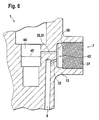
- Figure 6 shows a central bore on the injector body in this embodiment forms the central space in the injector body.
- the end face 38 runs in the connecting piece 7 two inlet bores 30, 31, of which only one is shown for reasons of reproduction from the end face 38 to a central bore 44.
- the central bore 44 is formed in the injector body 13 in a diameter 45, which is analogous to the illustration according to FIG. 2, the diameter 33 or 34 (compare illustration according to FIG. 4) Inlet bores 30, 31 exceeds many times.
- the further drilling 32 which extends from the end face on the connecting piece 7 to the nozzle inlet 9, via which a nozzle space, not shown in FIG. 6, is under extremely high pressure Fuel is applied.
- the embodiment variants of the solution according to the invention outlined in FIGS. 2 to 6 there is the advantage that the inlet bores 30 and 31 and a further bore 32 in the interior of the injector body 13 all in diameters 33, 34 and 35 respectively are that are many times smaller than the diameter 36, 45 through these holes 30, 31 and 32 acted on central rooms 5, 44.
- the invention offers proposed solution a strength potential on fuel injectors, which certainly with the pressure increase to be expected in the future on injection systems from direct-injection internal combustion engines is to be expected.
- This fixed high pressure strength potential which of the proposed solutions according to the invention lives, is with a merely inclined connection piece 7 as shown cannot be achieved from the prior art in FIG. 1, so that the high pressure resistance of this Injector is already maxed out.
Landscapes
- Engineering & Computer Science (AREA)
- Chemical & Material Sciences (AREA)
- Combustion & Propulsion (AREA)
- Mechanical Engineering (AREA)
- General Engineering & Computer Science (AREA)
- Physics & Mathematics (AREA)
- Fluid Mechanics (AREA)
- Fuel-Injection Apparatus (AREA)
Abstract
Description
- Figur 1
- einen aus dem Stande der Technik bekannten Kraftstoffinjektor mit schrägem Hochdruckanschluss.
- Figur 2
- einen Längsschnitt durch einen Injektor gemäß der Erfindung mit Ringraum im Inneren des Injektorkörpers,
- Figur 3
- einen Schnitt durch die Darstellung gemäß Figur 2,
- Figur 4
- die Ansicht gemäß des Schnittverlaufes "A-A",
- Figur 5.1
- eine Ausführungsvariante mit parallelen Zulaufbohrungen im Injektorkörper,
- Figur 5.2
- eine weitere Ausführungsvariante mit schräg gestellten Zulaufbohrungen im Injektorkörper,
- Fig. 5.3 + 5.4
- Zulaufbohrungen für Ringraum/Zentralbohrung und Düsenzulauf im ½-Lochmuster und
- Figur 6
- Zentralbohrungen in eine Zentralbohrung des Injektorkörpers mündende Zulaufbohrungen.
Claims (10)
- Injektor zum Einspritzen von Kraftstoff in den Brennraum einer Verbrennungskraftmaschine, der über einen Aktor (29) betätigbar ist und der einen im Injektorkörper (13) ausgebildeten zentralen Raum (5, 44) umfasst, über den unter hohem Druck stehender Kraftstoff in einen eine Düssennadel (4) betätigenden Steuerraum (3) eintritt, wobei der zentrale Raum (5, 44) über einen Anschluss (7) mit einer Hochdruckquelle verbunden ist, dadurch gekennzeichnet, dass im Injektorkörper (13) zwischen dem zentralen Raum (5, 44) und einer Stirnseite (38) am Anschluss (7) Zulaufbohrungen (30, 31) ausgebildet sind, deren Durchmesser (33, 34) um ein Vielfaches geringer als der Durchmesser (36, 45) des zentralen Raumes (5, 44) ist.
- Injektor gemäß Anspruch 1, dadurch gekennzeichnet, dass die Zulaufbohrungen (30, 31) im Injektorkörper (13) im wesentlichen in Parallel-Lage (39) zueinander verlaufen.
- Injektor gemäß Anspruch 1, dadurch gekennzeichnet, dass die Zulaufbohrung (30, 31) unter einem Winkel δ (40) geneigt zur Symmetrielinie des Anschlusses (7) im Injektorkörper (13) verlaufen.
- Injektor gemäß Anspruch 3, dadurch gekennzeichnet, dass die Zulaufbohrungen (30, 31) im Injektorkörper (13) tangential in den Begrenzungen des zentralen Raumes (5, 44) münden.
- Injektor gemäß Anspruch 1, dadurch gekennzeichnet, dass der zentrale Raum ein Ringraum (5) ist.
- Injektor gemäß Anspruch 1, dadurch gekennzeichnet, dass der zentrale Raum eine zentrale Bohrung (44) im Injektorkörper (13) ist.
- Injektor gemäß Anspruch 1, dadurch gekennzeichnet, dass in der Stirnseite (38) am Anschluss (7) eine weitere, einen Düsenzulauf (9) zur Einspritzdüse (12) direkt beaufschlagende, weitere Bohrung (32) ausgebildet ist.
- Injektor gemäß der Ansprüche 1 und 7, dadurch gekennzeichnet, dass die weitere Bohrung (32) an der Stirnfläche (38) in ½-Lochlagen (42, 43) zwischen den Zulaufbohrungen(30, 31) mündet.
- Injektor gemäß Anspruch 8, dadurch gekennzeichnet, dass die weitere Bohrung (32) an der Stirnfläche (38) oberhalb der Zulaufbohrungen (30, 31) liegt.
- Injektor gemäß Anspruch 8, dadurch gekennzeichnet, dass die weitere Bohrung (32) an der Stirnfläche (38) unterhalb der Zulaufbohrungen (30, 31) liegt.
Applications Claiming Priority (2)
| Application Number | Priority Date | Filing Date | Title |
|---|---|---|---|
| DE10132246 | 2001-07-04 | ||
| DE10132246A DE10132246A1 (de) | 2001-07-04 | 2001-07-04 | Kraftstoffinjektor mit hochdruckfestem Zulauf |
Publications (3)
| Publication Number | Publication Date |
|---|---|
| EP1273792A2 true EP1273792A2 (de) | 2003-01-08 |
| EP1273792A3 EP1273792A3 (de) | 2005-01-05 |
| EP1273792B1 EP1273792B1 (de) | 2011-09-28 |
Family
ID=7690471
Family Applications (1)
| Application Number | Title | Priority Date | Filing Date |
|---|---|---|---|
| EP02014392A Expired - Lifetime EP1273792B1 (de) | 2001-07-04 | 2002-06-28 | Kraftstoffinjektor mit hochdruckfestem Zulauf |
Country Status (4)
| Country | Link |
|---|---|
| US (1) | US6814301B2 (de) |
| EP (1) | EP1273792B1 (de) |
| JP (1) | JP2003035235A (de) |
| DE (1) | DE10132246A1 (de) |
Cited By (1)
| Publication number | Priority date | Publication date | Assignee | Title |
|---|---|---|---|---|
| WO2010006828A1 (de) * | 2008-07-14 | 2010-01-21 | Robert Bosch Gmbh | Kraftstoffinjektor mit hochdruckzulauf |
Families Citing this family (6)
| Publication number | Priority date | Publication date | Assignee | Title |
|---|---|---|---|---|
| DE10143947A1 (de) * | 2001-09-07 | 2003-04-03 | Bosch Gmbh Robert | Injektorkörper mit tangentialem Druckanschluss |
| AU2003275676A1 (en) * | 2002-10-29 | 2004-05-25 | Bosch Automotive Systems Corporation | High flow rate fuel valve and fuel supply pump with the valve |
| US20050106035A1 (en) * | 2002-10-29 | 2005-05-19 | Nobuo Aoki | High flow rate fuel valve and fuel supply pump with the valve |
| JP5218583B2 (ja) * | 2011-03-09 | 2013-06-26 | 株式会社デンソー | インジェクタ |
| JP6245681B2 (ja) * | 2013-06-03 | 2017-12-13 | ボッシュ株式会社 | 燃料噴射弁 |
| KR20200059343A (ko) * | 2018-11-20 | 2020-05-29 | 현대자동차주식회사 | 엔진의 연료 인젝터 |
Citations (2)
| Publication number | Priority date | Publication date | Assignee | Title |
|---|---|---|---|---|
| EP0753660A1 (de) | 1995-07-14 | 1997-01-15 | Isuzu Motors Limited | Kraftstoff-Einspritzvorrichtung für Brennkraftmaschinen |
| DE19650865A1 (de) | 1996-12-07 | 1998-06-10 | Bosch Gmbh Robert | Magnetventil |
Family Cites Families (9)
| Publication number | Priority date | Publication date | Assignee | Title |
|---|---|---|---|---|
| GB1412413A (en) * | 1971-10-28 | 1975-11-05 | Cav Ltd | Liquid fuel injection systems |
| JPH0286953A (ja) * | 1988-09-21 | 1990-03-27 | Kanesaka Gijutsu Kenkyusho:Kk | 燃料噴射弁 |
| JP2689721B2 (ja) * | 1990-11-16 | 1997-12-10 | トヨタ自動車株式会社 | 内燃機関の燃料圧力制御装置 |
| US5397055A (en) * | 1991-11-01 | 1995-03-14 | Paul; Marius A. | Fuel injector system |
| US5299919A (en) * | 1991-11-01 | 1994-04-05 | Paul Marius A | Fuel injector system |
| CH689282A5 (de) * | 1994-03-29 | 1999-01-29 | Christian Dipl-Ing Eth Mathis | Einspritzventil fuer eine insbesondere als Dieselmotor vorgesehene Brennkraftmaschine. |
| DE19640480B4 (de) * | 1996-09-30 | 2004-04-22 | Robert Bosch Gmbh | Kraftstoffhochdruckspeicher |
| IT1296143B1 (it) * | 1997-11-18 | 1999-06-09 | Elasis Sistema Ricerca Fiat | Dispositivo di comando di un iniettore di combustibile per motori a combustione interna. |
| DE19937946C1 (de) * | 1999-08-11 | 2001-04-19 | Bosch Gmbh Robert | Kraftstoffhochdruckspeicher für ein Kraftstoffeinspritzsystem für Brennkraftmaschinen |
-
2001
- 2001-07-04 DE DE10132246A patent/DE10132246A1/de not_active Ceased
-
2002
- 2002-06-28 EP EP02014392A patent/EP1273792B1/de not_active Expired - Lifetime
- 2002-07-02 US US10/189,122 patent/US6814301B2/en not_active Expired - Fee Related
- 2002-07-04 JP JP2002195952A patent/JP2003035235A/ja active Pending
Patent Citations (2)
| Publication number | Priority date | Publication date | Assignee | Title |
|---|---|---|---|---|
| EP0753660A1 (de) | 1995-07-14 | 1997-01-15 | Isuzu Motors Limited | Kraftstoff-Einspritzvorrichtung für Brennkraftmaschinen |
| DE19650865A1 (de) | 1996-12-07 | 1998-06-10 | Bosch Gmbh Robert | Magnetventil |
Cited By (2)
| Publication number | Priority date | Publication date | Assignee | Title |
|---|---|---|---|---|
| WO2010006828A1 (de) * | 2008-07-14 | 2010-01-21 | Robert Bosch Gmbh | Kraftstoffinjektor mit hochdruckzulauf |
| US8608093B2 (en) | 2008-07-14 | 2013-12-17 | Robert Bosch Gmbh | Fuel injector having a high-pressure inlet |
Also Published As
| Publication number | Publication date |
|---|---|
| JP2003035235A (ja) | 2003-02-07 |
| EP1273792A3 (de) | 2005-01-05 |
| EP1273792B1 (de) | 2011-09-28 |
| US20030080217A1 (en) | 2003-05-01 |
| US6814301B2 (en) | 2004-11-09 |
| DE10132246A1 (de) | 2003-01-23 |
Similar Documents
| Publication | Publication Date | Title |
|---|---|---|
| EP2812559B1 (de) | Brennstoffeinspritzventil und vorrichtung zum einspritzen von brennstoff | |
| DE10210282A1 (de) | Vorrichtung zum Einspritzen von Kraftstoff an stationären Verbrennungskraftmaschinen | |
| DE3445405A1 (de) | Elektromagnetisch betaetigbares ventil | |
| DE102013013266A1 (de) | Brennstoffeinspritzvorrichtung mit doppeltem Rückschlagelement mit einzelner Betätigungsvorrichtung | |
| DE102007056913A1 (de) | Einspritzdüse für Kraftstoff mit Kugelventil | |
| EP1395744B1 (de) | Kraftstoff-einspritzvorrichtung für brennkraftmaschinen, insbesondere common-rail-injektor, sowie kraftstoffsystem und brennkraftmaschine | |
| EP1395749B1 (de) | Brennstoffeinspritzventil | |
| EP2387661A1 (de) | Kraftstoffinjektor für brennkraftmaschinen | |
| DE10105031A1 (de) | Vorrichtung zur Dämpfung von Druckpulsationen in Hochdruckeinspritzsystemen | |
| EP1273792A2 (de) | Kraftstoffinjektor mit hochdruckfestem Zulauf | |
| DE10313225A1 (de) | Kraftstoffeinspritzventil für Brennkraftmaschine | |
| EP1346143B1 (de) | Kraftstoffeinspritzventil für brennkraftmaschinen | |
| EP1117921B1 (de) | Einspritzvetil für ein Common-Rail Kraftstoffsystem | |
| EP1404961A1 (de) | Kraftstoffinjektor mit einspritzverlaufsformung durch schaltbare drosselelemente | |
| DE102006046898A1 (de) | Drosselplatte für Magnetventil | |
| DE102006015745A1 (de) | Kraftstoffinjektor mit direktgesteuertem Einspritzventilglied | |
| DE102008041502A1 (de) | Kraftstoffinjektor mit einem Magnetventil | |
| EP1527272B1 (de) | Kraftstoffinjektor mit hochdruckfestem anschlussbereich | |
| EP2156047A1 (de) | Kraftstoffinjektor mit geringem verschleiss | |
| DE10147830B4 (de) | Kraftstoffinjektor | |
| DE102006049830A1 (de) | Kraftstoffeinspritzventileinrichtung | |
| DE544070C (de) | Fluessigkeitsgesteuertes Brennstoffeinspritzventil fuer Brennkraftmaschinen mit Druckzerstaeubung | |
| WO2008125537A1 (de) | Injektor | |
| WO2003004863A1 (de) | Kraftstoffinjektor mit 2-wege-ventilsteuerung | |
| WO2009138279A1 (de) | Magnetventil mit ankerschlitzung |
Legal Events
| Date | Code | Title | Description |
|---|---|---|---|
| PUAI | Public reference made under article 153(3) epc to a published international application that has entered the european phase |
Free format text: ORIGINAL CODE: 0009012 |
|
| AK | Designated contracting states |
Kind code of ref document: A2 Designated state(s): AT BE CH CY DE DK ES FI FR GB GR IE IT LI LU MC NL PT SE TR |
|
| AX | Request for extension of the european patent |
Free format text: AL;LT;LV;MK;RO;SI |
|
| PUAL | Search report despatched |
Free format text: ORIGINAL CODE: 0009013 |
|
| AK | Designated contracting states |
Kind code of ref document: A3 Designated state(s): AT BE CH CY DE DK ES FI FR GB GR IE IT LI LU MC NL PT SE TR |
|
| AX | Request for extension of the european patent |
Extension state: AL LT LV MK RO SI |
|
| 17P | Request for examination filed |
Effective date: 20050705 |
|
| AKX | Designation fees paid |
Designated state(s): DE FR IT |
|
| 17Q | First examination report despatched |
Effective date: 20080919 |
|
| GRAP | Despatch of communication of intention to grant a patent |
Free format text: ORIGINAL CODE: EPIDOSNIGR1 |
|
| GRAS | Grant fee paid |
Free format text: ORIGINAL CODE: EPIDOSNIGR3 |
|
| GRAA | (expected) grant |
Free format text: ORIGINAL CODE: 0009210 |
|
| AK | Designated contracting states |
Kind code of ref document: B1 Designated state(s): DE FR IT |
|
| REG | Reference to a national code |
Ref country code: DE Ref legal event code: R096 Ref document number: 50215220 Country of ref document: DE Effective date: 20111215 |
|
| PLBE | No opposition filed within time limit |
Free format text: ORIGINAL CODE: 0009261 |
|
| STAA | Information on the status of an ep patent application or granted ep patent |
Free format text: STATUS: NO OPPOSITION FILED WITHIN TIME LIMIT |
|
| 26N | No opposition filed |
Effective date: 20120629 |
|
| REG | Reference to a national code |
Ref country code: DE Ref legal event code: R097 Ref document number: 50215220 Country of ref document: DE Effective date: 20120629 |
|
| PGFP | Annual fee paid to national office [announced via postgrant information from national office to epo] |
Ref country code: FR Payment date: 20130703 Year of fee payment: 12 |
|
| PGFP | Annual fee paid to national office [announced via postgrant information from national office to epo] |
Ref country code: DE Payment date: 20130828 Year of fee payment: 12 |
|
| PGFP | Annual fee paid to national office [announced via postgrant information from national office to epo] |
Ref country code: IT Payment date: 20130621 Year of fee payment: 12 |
|
| REG | Reference to a national code |
Ref country code: DE Ref legal event code: R119 Ref document number: 50215220 Country of ref document: DE |
|
| REG | Reference to a national code |
Ref country code: FR Ref legal event code: ST Effective date: 20150227 |
|
| REG | Reference to a national code |
Ref country code: DE Ref legal event code: R119 Ref document number: 50215220 Country of ref document: DE Effective date: 20150101 |
|
| PG25 | Lapsed in a contracting state [announced via postgrant information from national office to epo] |
Ref country code: DE Free format text: LAPSE BECAUSE OF NON-PAYMENT OF DUE FEES Effective date: 20150101 Ref country code: IT Free format text: LAPSE BECAUSE OF NON-PAYMENT OF DUE FEES Effective date: 20140628 |
|
| PG25 | Lapsed in a contracting state [announced via postgrant information from national office to epo] |
Ref country code: FR Free format text: LAPSE BECAUSE OF NON-PAYMENT OF DUE FEES Effective date: 20140630 |