EP1273802A1 - Pompe à vide - Google Patents
Pompe à vide Download PDFInfo
- Publication number
- EP1273802A1 EP1273802A1 EP02254522A EP02254522A EP1273802A1 EP 1273802 A1 EP1273802 A1 EP 1273802A1 EP 02254522 A EP02254522 A EP 02254522A EP 02254522 A EP02254522 A EP 02254522A EP 1273802 A1 EP1273802 A1 EP 1273802A1
- Authority
- EP
- European Patent Office
- Prior art keywords
- rotor
- circumferential surface
- pump case
- outer circumferential
- vacuum pump
- Prior art date
- Legal status (The legal status is an assumption and is not a legal conclusion. Google has not performed a legal analysis and makes no representation as to the accuracy of the status listed.)
- Withdrawn
Links
- 238000005260 corrosion Methods 0.000 claims abstract description 34
- 238000000034 method Methods 0.000 claims abstract description 30
- 229920005989 resin Polymers 0.000 claims abstract description 18
- 239000011347 resin Substances 0.000 claims abstract description 18
- 229920001187 thermosetting polymer Polymers 0.000 claims abstract description 16
- 238000005520 cutting process Methods 0.000 claims description 13
- 230000007797 corrosion Effects 0.000 abstract description 13
- 230000006378 damage Effects 0.000 abstract description 10
- 230000008021 deposition Effects 0.000 abstract description 6
- 239000010408 film Substances 0.000 description 24
- 229910000838 Al alloy Inorganic materials 0.000 description 16
- 239000007789 gas Substances 0.000 description 11
- 238000004519 manufacturing process Methods 0.000 description 10
- 238000010586 diagram Methods 0.000 description 8
- PXHVJJICTQNCMI-UHFFFAOYSA-N Nickel Chemical compound [Ni] PXHVJJICTQNCMI-UHFFFAOYSA-N 0.000 description 6
- 239000004065 semiconductor Substances 0.000 description 6
- 230000000694 effects Effects 0.000 description 5
- 238000007747 plating Methods 0.000 description 5
- 238000005536 corrosion prevention Methods 0.000 description 4
- 238000005336 cracking Methods 0.000 description 3
- BHEPBYXIRTUNPN-UHFFFAOYSA-N hydridophosphorus(.) (triplet) Chemical compound [PH] BHEPBYXIRTUNPN-UHFFFAOYSA-N 0.000 description 3
- 229910052759 nickel Inorganic materials 0.000 description 3
- ZAMOUSCENKQFHK-UHFFFAOYSA-N Chlorine atom Chemical compound [Cl] ZAMOUSCENKQFHK-UHFFFAOYSA-N 0.000 description 2
- YCKRFDGAMUMZLT-UHFFFAOYSA-N Fluorine atom Chemical compound [F] YCKRFDGAMUMZLT-UHFFFAOYSA-N 0.000 description 2
- 239000000853 adhesive Substances 0.000 description 2
- 230000001070 adhesive effect Effects 0.000 description 2
- 229910045601 alloy Inorganic materials 0.000 description 2
- 239000000956 alloy Substances 0.000 description 2
- 229910052801 chlorine Inorganic materials 0.000 description 2
- 239000000460 chlorine Substances 0.000 description 2
- YNAAFGQNGMFIHH-UHFFFAOYSA-N ctk8g8788 Chemical compound [S]F YNAAFGQNGMFIHH-UHFFFAOYSA-N 0.000 description 2
- 239000003822 epoxy resin Substances 0.000 description 2
- 239000011737 fluorine Substances 0.000 description 2
- 229910052731 fluorine Inorganic materials 0.000 description 2
- 239000000463 material Substances 0.000 description 2
- 229920000647 polyepoxide Polymers 0.000 description 2
- 239000007921 spray Substances 0.000 description 2
- 230000003068 static effect Effects 0.000 description 2
- 229920003002 synthetic resin Polymers 0.000 description 2
- 239000000057 synthetic resin Substances 0.000 description 2
- 239000010409 thin film Substances 0.000 description 2
- 238000003483 aging Methods 0.000 description 1
- XAGFODPZIPBFFR-UHFFFAOYSA-N aluminium Chemical compound [Al] XAGFODPZIPBFFR-UHFFFAOYSA-N 0.000 description 1
- 229910052782 aluminium Inorganic materials 0.000 description 1
- QVGXLLKOCUKJST-UHFFFAOYSA-N atomic oxygen Chemical compound [O] QVGXLLKOCUKJST-UHFFFAOYSA-N 0.000 description 1
- 230000004888 barrier function Effects 0.000 description 1
- 239000011248 coating agent Substances 0.000 description 1
- 238000000576 coating method Methods 0.000 description 1
- 239000002131 composite material Substances 0.000 description 1
- 238000001312 dry etching Methods 0.000 description 1
- 238000001035 drying Methods 0.000 description 1
- 238000005530 etching Methods 0.000 description 1
- 230000004927 fusion Effects 0.000 description 1
- LNEPOXFFQSENCJ-UHFFFAOYSA-N haloperidol Chemical compound C1CC(O)(C=2C=CC(Cl)=CC=2)CCN1CCCC(=O)C1=CC=C(F)C=C1 LNEPOXFFQSENCJ-UHFFFAOYSA-N 0.000 description 1
- 239000000314 lubricant Substances 0.000 description 1
- 239000007769 metal material Substances 0.000 description 1
- 239000001301 oxygen Substances 0.000 description 1
- 229910052760 oxygen Inorganic materials 0.000 description 1
- 239000002245 particle Substances 0.000 description 1
- 230000002265 prevention Effects 0.000 description 1
- 125000006850 spacer group Chemical group 0.000 description 1
- 238000005211 surface analysis Methods 0.000 description 1
Images

Classifications
-
- F—MECHANICAL ENGINEERING; LIGHTING; HEATING; WEAPONS; BLASTING
- F04—POSITIVE - DISPLACEMENT MACHINES FOR LIQUIDS; PUMPS FOR LIQUIDS OR ELASTIC FLUIDS
- F04D—NON-POSITIVE-DISPLACEMENT PUMPS
- F04D19/00—Axial-flow pumps
- F04D19/02—Multi-stage pumps
- F04D19/04—Multi-stage pumps specially adapted to the production of a high vacuum, e.g. molecular pumps
-
- F—MECHANICAL ENGINEERING; LIGHTING; HEATING; WEAPONS; BLASTING
- F04—POSITIVE - DISPLACEMENT MACHINES FOR LIQUIDS; PUMPS FOR LIQUIDS OR ELASTIC FLUIDS
- F04D—NON-POSITIVE-DISPLACEMENT PUMPS
- F04D29/00—Details, component parts, or accessories
- F04D29/02—Selection of particular materials
- F04D29/023—Selection of particular materials especially adapted for elastic fluid pumps
-
- F—MECHANICAL ENGINEERING; LIGHTING; HEATING; WEAPONS; BLASTING
- F04—POSITIVE - DISPLACEMENT MACHINES FOR LIQUIDS; PUMPS FOR LIQUIDS OR ELASTIC FLUIDS
- F04D—NON-POSITIVE-DISPLACEMENT PUMPS
- F04D29/00—Details, component parts, or accessories
- F04D29/66—Combating cavitation, whirls, noise, vibration or the like; Balancing
- F04D29/661—Combating cavitation, whirls, noise, vibration or the like; Balancing especially adapted for elastic fluid pumps
- F04D29/662—Balancing of rotors
-
- F—MECHANICAL ENGINEERING; LIGHTING; HEATING; WEAPONS; BLASTING
- F05—INDEXING SCHEMES RELATING TO ENGINES OR PUMPS IN VARIOUS SUBCLASSES OF CLASSES F01-F04
- F05D—INDEXING SCHEME FOR ASPECTS RELATING TO NON-POSITIVE-DISPLACEMENT MACHINES OR ENGINES, GAS-TURBINES OR JET-PROPULSION PLANTS
- F05D2230/00—Manufacture
- F05D2230/90—Coating; Surface treatment
-
- F—MECHANICAL ENGINEERING; LIGHTING; HEATING; WEAPONS; BLASTING
- F05—INDEXING SCHEMES RELATING TO ENGINES OR PUMPS IN VARIOUS SUBCLASSES OF CLASSES F01-F04
- F05D—INDEXING SCHEME FOR ASPECTS RELATING TO NON-POSITIVE-DISPLACEMENT MACHINES OR ENGINES, GAS-TURBINES OR JET-PROPULSION PLANTS
- F05D2260/00—Function
- F05D2260/95—Preventing corrosion
-
- F—MECHANICAL ENGINEERING; LIGHTING; HEATING; WEAPONS; BLASTING
- F05—INDEXING SCHEMES RELATING TO ENGINES OR PUMPS IN VARIOUS SUBCLASSES OF CLASSES F01-F04
- F05D—INDEXING SCHEME FOR ASPECTS RELATING TO NON-POSITIVE-DISPLACEMENT MACHINES OR ENGINES, GAS-TURBINES OR JET-PROPULSION PLANTS
- F05D2300/00—Materials; Properties thereof
- F05D2300/40—Organic materials
- F05D2300/44—Resins
-
- F—MECHANICAL ENGINEERING; LIGHTING; HEATING; WEAPONS; BLASTING
- F05—INDEXING SCHEMES RELATING TO ENGINES OR PUMPS IN VARIOUS SUBCLASSES OF CLASSES F01-F04
- F05D—INDEXING SCHEME FOR ASPECTS RELATING TO NON-POSITIVE-DISPLACEMENT MACHINES OR ENGINES, GAS-TURBINES OR JET-PROPULSION PLANTS
- F05D2300/00—Materials; Properties thereof
- F05D2300/60—Properties or characteristics given to material by treatment or manufacturing
- F05D2300/611—Coating
Definitions
- the present invention relates to a vacuum pump used for a semiconductor manufacturing apparatus, an electron microscope, a surface analysis apparatus, a mass spectrometer, a particle accelerator, an experimental fusion apparatus, or the like.
- the invention relates to a vacuum pump in which anti-corrosive processing is necessary, like one used in a semiconductor manufacturing apparatus.
- a vacuum pump such as a turbo molecular pump is used as means for exhausting gas within a processing chamber, for forming a given high vacuum degree.
- a rotational body of this type of vacuum pump is normally formed of an aluminum alloy.
- an anti-corrosive processing is performed in which the surface of a rotational body made from an aluminum alloy is coated with an anti-corrosive prevention film such as a nickel phosphorous alloy plating.
- a balancing method a method is generally known in which the mass of the rotational body is changed by partially cutting off the outer circumferential surface or the inner circumferential surface of the rotational body by using a cutting tool such as a drill or a router, thus performing fine adjustments of the balance.
- balancing is performed by cutting in the above-stated manner after conducting the anti-corrosion process, and a portion of the anti-corrosive film coated on the surface of the rotational body is removed by the cutting tool such as a drill or a router. Therefore, corrosion develops in a cut off portion where the aluminum alloy of the rotational body itself is exposed due to a corrosive gas, stress corrosion cracks progress in the cut off portion due to high speed rotation of the rotational body, and in the worst case, this may lead to destruction of the rotational body, affecting the outside of the vacuum pump as well.
- the aluminum alloy of the rotational body itself is exposed in the portion cut off for balancing, and if debris or the like generated by etching a wafer surface in a semiconductor manufacturing process is mixed into the inside of the vacuum pump, then the debris will adhere to the surface of the aluminum in the cut off portion, and will be deposited as a product.
- the debris will be easily deposited on the surface of the deposited product, and if chain deposition of the product on the surface of the rotational body progresses in this manner, then the clearance between the fixed side of the vacuum pump and the rotational body will become smaller. Accordingly, there is a concern that the fixed side will have critical damage when the product deposited on the rotating body contacts the fixed side.
- an object of the present invention is to provide a vacuum pump in which destruction of a rotational body due to corrosion can be prevented, and in which the deposition of the product is reduced, preventing damage due to contact between the rotational body and a fixed side.
- a vacuum pump is provided with: a pump case having a gas inlet port opened in its top surface; a rotor shaft rotatably supported within the pump case; a plurality of rotor blades formed on an outer circumferential surface of a rotor that is fixed to the rotor shaft and housed within the pump case; a plurality of stator blades fixed within the pump case and positioned alternately with the plurality of rotor blades; a driving motor for rotating the rotor shaft; an anti-corrosive film layer formed on a surface of the rotor; and a balancing hole formed by partially cutting off an inner circumferential surface or an outer circumferential surface of the rotor, the vacuum pump being characterized in that anti-corrosion process is performed on the balancing hole.
- the anti-corrosion process employed here means a process in which a thermosetting resin film layer is formed on a surface of the balancing hole.
- Synthetic resins having superior heat resistance characteristics and superior anti-corrosion characteristics such as epoxy resins and fluorine resins, for example, can be used as the thermosetting resin.
- a vacuum pump is provided with: a pump case having a gas inlet port opened in its top surface; a rotor shaft rotatably supported within the pump case; aplurality of rotor blades formed on an outer circumferential surface of a rotor that is fixed to the rotor shaft and housed within the pump case; a plurality of stator blades fixed within the pump case and positioned alternately with the plurality of rotor blades; a driving motor for rotating the rotor shaft; and a balancing hole formed by partially cutting off an inner circumferential surface or an outer circumferential surface of the rotor; the vacuum pump being characterized in that an anti-corrosive film layer is formed on a surface of the rotor.
- Fig. 1 is a vertical cross sectional diagram showing the structure of a first embodiment of a vacuum pump according to the present invention.
- a vacuum pump P of this embodiment is mainly structured from a pump case 1 composed of a cylindrical portion 1-1 and a base 1-2 attached to a lower end of the cylindrical portion 1-1, and a pump mechanism portion housed in the pump case 1.
- An upper surface of the pump case 1 is opened, serving as a gas inlet port 2, and a not shown vacuum container, such as a process chamber, is screwed into the gas inlet port 2 and fixed with a bolt, and an exhaust pipe that serves as a gas exhaust port 3 is formed in one side surface of a lower portion of the pump case 1.
- a lower base of the pump case 1 is covered by a rear cover 1-3, and a stator column 4 is disposed above the rear cover 1-3 in a standing manner toward an inside portion of the pump case 1 and is screwed into and fixed to the base 1-2.
- a rotor shaft 5 is bearing-supported in the radial direction and in the axial direction by a radial direction electromagnet 6-1 and an axial direction electromagnet 6-2, respectively, which are formed in an inside portion of the stator column 4 so that the rotor 5 passing through between both ends of the stator column 4 is able to rotate.
- reference numeral 7 denotes a ball bearing to which a dry lubricant has been applied. The ball bearing 7 protects the rotor shaft 5 and the electromagnets 6-1 and 6-2 from contacting and supports the rotor shaft 5 when an electric power source for the magnetic bearings fails, the electromagnets not being in contact with the rotor shaft 5 during normal operation.
- a rotor 8 formed in a cylindrical shape is disposed in the inside portion of the pump case 1 so as to surround the stator column 4, an upper end of the rotor 8 extends to the vicinity of the gas inlet port 2, and is fixed to the rotor shaft 5 by screwing with a bolt.
- a driving motor 9 composed of a high frequency motor or the like is provided between the rotor shaft 5 and the stator column 4, and the rotor shaft 5 and the rotor 8 are rotated at high speed by the driving motor 9.
- the pump mechanism portion of the vacuum pump P of this embodiment is housed within the pump case 1 and employs a composite type pump mechanism composed of turbo molecular pump mechanism portion P A of upper half, and thread groove pump mechanism portion P B of lower half, which are defined between an outer circumferential surface of the rotor 8 and an inner circumferential surface of the pump case 1.
- the turbo molecular pump mechanism portion P A is structured by rotator blades 10 that rotate at high speed and static stator blades 11 that are fixed.
- a plurality of processed blade shape rotor blades 10, 10, ... are formed on the outer circumferential surface of the upper half of the rotor 8 from the gas inlet port 2 side in a direction to a central rotation axis L of the rotor 8.
- a plurality of stator blades 11, 11, ... disposed alternately between the plurality of rotor blades 10, 10, ... are formed on the inner circumferential surface of the upper half of the pump case 1, and are fixed through spacers 12, 12, ...
- the thread groove pump mechanism portion P B is structured by a cylindrical surface 8a of the rotor 8 rotating at high speed and a static thread groove 13.
- the outer circumferential surface of the lower half of the rotor 8 serves as the flat cylindrical surface 8a
- a cylindrical screw stator 14 is disposed so as to oppose the cylindrical surface 8a of the rotor 8 with a narrow gap.
- the thread groove 13 is carved in the screw stator 14.
- thread groove 13 can be carved in the outer circumferential surface of the lower half of the rotor 8. Also, an opposing surface of the screw stator 14 provided on the inner circumference of the lower half of the pump case 1, to the rotor 8 can be formed in the flat cylindrical surface.
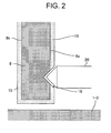
- the vacuum pump P of this embodiment is used under a severe environment exposed to corrosive chlorine and fluorine sulfide gasses during semiconductor manufacturing processes, an anti-corrosive process is performed as shown in Fig. 2 for forming an even coating of an anti-corrosive film layer 15 by means of a plating, such as a nickel phosphorous oxide plating, at a thickness on the order of 10 to 20 ⁇ m on the outer circumferential surface 8a and the inner circumferential surface 8b of the rotor 8, which is formed by an aluminum alloy or the like.
- a plating such as a nickel phosphorous oxide plating
- balancing holes 16, 16, ... maybe formed by partially cutting off the surface of the anti-corrosive film layer 15 formed in the outer circumferential surface 8a or the inner circumferential surface 8b of the rotor 8 using a cutting tool 20 such as a drill or a router; changing the mass of the rotor 8 and performing fine adjustments of the balance of the rotational body; and then an anti-corrosion process is performed on the surface of the balancing holes 16.
- the surface of the balancing holes 16 after performing the rotational body balancing is in a state in which a portion of the aluminum alloy of main body of the rotor 8 is exposed because a portion of the anti-corrosive film layer 15 coated on the surface of the outer circumferential surface 8a and the inner circumferential surface 8b of the rotor 8 is cut off, as shown in Fig. 2.
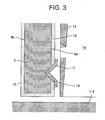
- thermosetting resin film layer 17 having superior heat resistance characteristics and superior anti-corrosion characteristics, such as an epoxy resin, a fluorine resin, or the like is formed on the surface of the balancing holes 16, as shown in Fig. 3.
- thermosetting resin has good adhesive characteristics with respect to metallic materials and has strong adhesive force with respect to curved surfaces like the inner circumferential surface 8b and the outer circumferential surface 8a of the rotor 8, and therefore peeling due to centrifugal force of the rotational body will not occur. Further, the thermosetting resin has superior oxygen barrier characteristics, and therefore anti-corrosion process can be performed by a relatively simple method of only forming the thermosetting resin film layer 17 on the surface of the balancing holes 16.
- thermosetting resin film layer 17 As a method of forming the thermosetting resin film layer 17, a known spray application process using a spray gun or the like, followed by age hardening by the rotor 8 at room temperature or a required temperature may be employed, whereby conducting a uniform application at least on the surface of the aluminum alloy of the balancing holes 16 at a thickness of 10 to 20 ⁇ m.
- thermosetting resin film layer 17 is formed into a thick film, anti-corrosion performance can be increased, and corrosion of the balancing holes 16 can be prevented over a long period of time.
- the gap between the outer circumferential surface 8a of the rotor 8 and the screw stator 14 becomes narrower, the rotational body and the fixed side of the vacuum pump come into contact, and the fixed side is damaged, the aforementioned film thickness range is appropriate.
- the weight of the thermosetting resin film layer 17 after hardening and drying is set on the order of 1 to 10 mg with respect to the number of balancing holes 16, and considering the increase in weight due to the thermosetting resin film layer 17, it is necessary to form the synthetic resin film layer 17 after performing a little excess amount of material cutting for balancing.
- the aluminum alloy surface of the balancing holes 16 formed in the surface of the outer circumferential surface 8a or the inner circumferential surface 8b of the rotor 8 is covered by the thermosetting resin film layer 17 as an anti-corrosion process, and therefore corrosion due to a corrosive gas does not develop in the aluminum alloy surface of the balancing holes 16, stress corrosion cracking of the balancing holes due to high speed rotation of the rotational body can be prevented, and rotor destruction due to corrosion can be prevented from happening.
- thermosetting resin film layer 17 can be formed on the aluminum alloy surface of the balancing holes 16b into a thin film as an anti-corrosion process, and deposition of the product adhering to the aluminum alloy can be reduced, and therefore damage due to contact between the rotational body and the fixed side can be prevented.
- the basic structure of the vacuum pump in this second embodiment is similar to the vacuum pump shown in Fig. 1, and therefore identical reference numerals are attached to identical portions, and a detailed explanation of those portions is omitted.
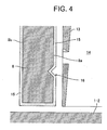
- the vacuum pump in this second embodiment is characterized in that the balancing holes 16 are formed by removing a portion of the inner circumferential surface 8b or the outer circumferential surface 8a of the rotor 8, and in that the corrosion prevention layer 15 is formed on the inner circumferential surface 8b and the outer circumferential surface 8a of the rotor 8, as shown in Fig. 4.
- a portion of the outer circumferential surface 8a or the inner circumferential surface 8b of the rotor 8 formed by the aluminum alloy or the like is removed by using the cutting tool 20 such as a drill or a router, changing the mass of the rotor 8 and performing fine adjustments of the balance of the rotational body, after which the corrosion prevention film layer 15 is uniformly coated to a thickness on the order of 10 to 20 ⁇ m by plating a nickel phosphorous alloy plating or the like, performing anti-corrosion process at the same time to the rotor 8 and to the balancing holes 16.
- the cutting tool 20 such as a drill or a router
- the process step for forming the thermosetting resin film layer 17 for anti-corrosion process of the balancing holes 16 can be omitted, anti-corrosion process of the balancing holes 16 can be simplified, and the manufacturing costs of the vacuum pump relating to anti-corrosion process can be lowered.
- the corrosion prevention film layer 15 is formed uniformly over the entire surface of the rotor 8 after performing balancing as stated above, and therefore it is not necessary to remove an excess amount of material in order to adjust the balance.
- the present invention can also be applied, of course, to other pumps that utilize rotation of a rotating body, such as a drag pump, and it is also possible to suitably change the locations in which the balancing holes are formed for design reasons.
Landscapes
- Engineering & Computer Science (AREA)
- Mechanical Engineering (AREA)
- General Engineering & Computer Science (AREA)
- Non-Positive Displacement Air Blowers (AREA)
- Structures Of Non-Positive Displacement Pumps (AREA)
Applications Claiming Priority (2)
| Application Number | Priority Date | Filing Date | Title |
|---|---|---|---|
| JP2001202297A JP2003021092A (ja) | 2001-07-03 | 2001-07-03 | 真空ポンプ |
| JP2001202297 | 2001-07-03 |
Publications (1)
| Publication Number | Publication Date |
|---|---|
| EP1273802A1 true EP1273802A1 (fr) | 2003-01-08 |
Family
ID=19039128
Family Applications (1)
| Application Number | Title | Priority Date | Filing Date |
|---|---|---|---|
| EP02254522A Withdrawn EP1273802A1 (fr) | 2001-07-03 | 2002-06-27 | Pompe à vide |
Country Status (4)
| Country | Link |
|---|---|
| US (1) | US20030021672A1 (fr) |
| EP (1) | EP1273802A1 (fr) |
| JP (1) | JP2003021092A (fr) |
| KR (1) | KR20030004118A (fr) |
Cited By (3)
| Publication number | Priority date | Publication date | Assignee | Title |
|---|---|---|---|---|
| EP1596068A3 (fr) * | 2004-05-10 | 2007-01-10 | BOC Edwards Japan Limited | Pompe à vide |
| CN110199127A (zh) * | 2017-02-08 | 2019-09-03 | 埃地沃兹日本有限公司 | 真空泵、真空泵所具备的旋转部及不平衡修正方法 |
| EP3550150A1 (fr) * | 2014-03-07 | 2019-10-09 | Pfeiffer Vacuum Gmbh | Procédé d'equilibrage d'un rotor d'une pompe à vide ou d'un rotor d'une unité de rotation pour une pompe à vide |
Families Citing this family (7)
| Publication number | Priority date | Publication date | Assignee | Title |
|---|---|---|---|---|
| JP2003021093A (ja) * | 2001-07-05 | 2003-01-24 | Boc Edwards Technologies Ltd | 真空ポンプ |
| JP5494807B2 (ja) * | 2010-08-06 | 2014-05-21 | 株式会社島津製作所 | 真空ポンプ |
| DE102011105806A1 (de) * | 2011-05-05 | 2012-11-08 | Pfeiffer Vacuum Gmbh | Vakuumpumpe mit Rotor |
| US20140127031A1 (en) * | 2011-07-21 | 2014-05-08 | Tohoku University | Screw rotor for exhaust pump, method for manufacturing the same, gas exhaust pump having screw rotor, and manufacturing method and assembly method of the same |
| US10585291B2 (en) | 2017-04-28 | 2020-03-10 | Yonatan Gerlitz | Eye safety system for lasers |
| JP6973348B2 (ja) * | 2018-10-15 | 2021-11-24 | 株式会社島津製作所 | 真空ポンプ |
| JP7671586B2 (ja) | 2021-01-18 | 2025-05-02 | エドワーズ株式会社 | 真空ポンプとその回転体 |
Citations (4)
| Publication number | Priority date | Publication date | Assignee | Title |
|---|---|---|---|---|
| GB687976A (en) * | 1949-12-23 | 1953-02-25 | Vickers Electrical Co Ltd | Improved curing process for thermosetting resinous coatings |
| DE4239391A1 (en) * | 1991-11-27 | 1993-06-09 | Electro Chemical Engineering Gmbh, Zug, Ch | Aluminium magnesium, titanium wear resistant rotor - comprises oxide ceramic layer with fluoro polymer, e.g. poly:tetra:fluoroethylene, for resistance to corrosion for turbo mol. pump |
| EP0799999A2 (fr) * | 1996-04-05 | 1997-10-08 | VARIAN S.p.A. | Rotor pour pompe turbomoléculaire |
| US6164945A (en) * | 1998-02-13 | 2000-12-26 | Ebara Corporation | Vacuum pump rotor and method of manufacturing the same |
Family Cites Families (3)
| Publication number | Priority date | Publication date | Assignee | Title |
|---|---|---|---|---|
| JP2527398B2 (ja) * | 1992-06-05 | 1996-08-21 | 財団法人真空科学研究所 | タ―ボ分子ポンプ |
| JPH0783189A (ja) * | 1993-09-17 | 1995-03-28 | Hitachi Ltd | ターボ真空ポンプ |
| US5938406A (en) * | 1997-04-18 | 1999-08-17 | Varian, Inc. | Rotor for turbomolecular pump |
-
2001
- 2001-07-03 JP JP2001202297A patent/JP2003021092A/ja not_active Withdrawn
-
2002
- 2002-06-27 EP EP02254522A patent/EP1273802A1/fr not_active Withdrawn
- 2002-07-02 KR KR1020020037959A patent/KR20030004118A/ko not_active Withdrawn
- 2002-07-03 US US10/187,566 patent/US20030021672A1/en not_active Abandoned
Patent Citations (4)
| Publication number | Priority date | Publication date | Assignee | Title |
|---|---|---|---|---|
| GB687976A (en) * | 1949-12-23 | 1953-02-25 | Vickers Electrical Co Ltd | Improved curing process for thermosetting resinous coatings |
| DE4239391A1 (en) * | 1991-11-27 | 1993-06-09 | Electro Chemical Engineering Gmbh, Zug, Ch | Aluminium magnesium, titanium wear resistant rotor - comprises oxide ceramic layer with fluoro polymer, e.g. poly:tetra:fluoroethylene, for resistance to corrosion for turbo mol. pump |
| EP0799999A2 (fr) * | 1996-04-05 | 1997-10-08 | VARIAN S.p.A. | Rotor pour pompe turbomoléculaire |
| US6164945A (en) * | 1998-02-13 | 2000-12-26 | Ebara Corporation | Vacuum pump rotor and method of manufacturing the same |
Cited By (6)
| Publication number | Priority date | Publication date | Assignee | Title |
|---|---|---|---|---|
| EP1596068A3 (fr) * | 2004-05-10 | 2007-01-10 | BOC Edwards Japan Limited | Pompe à vide |
| US7572096B2 (en) | 2004-05-10 | 2009-08-11 | Boc Edwards Japan Limited | Vacuum pump |
| EP3550150A1 (fr) * | 2014-03-07 | 2019-10-09 | Pfeiffer Vacuum Gmbh | Procédé d'equilibrage d'un rotor d'une pompe à vide ou d'un rotor d'une unité de rotation pour une pompe à vide |
| CN111473000A (zh) * | 2014-03-07 | 2020-07-31 | 普发真空有限公司 | 用于平衡真空泵转子或真空泵旋转单元转子的方法 |
| CN110199127A (zh) * | 2017-02-08 | 2019-09-03 | 埃地沃兹日本有限公司 | 真空泵、真空泵所具备的旋转部及不平衡修正方法 |
| CN110199127B (zh) * | 2017-02-08 | 2021-10-29 | 埃地沃兹日本有限公司 | 真空泵、真空泵所具备的旋转部及不平衡修正方法 |
Also Published As
| Publication number | Publication date |
|---|---|
| KR20030004118A (ko) | 2003-01-14 |
| JP2003021092A (ja) | 2003-01-24 |
| US20030021672A1 (en) | 2003-01-30 |
Similar Documents
| Publication | Publication Date | Title |
|---|---|---|
| EP1314891B1 (fr) | Pompe à vide | |
| EP1596068B1 (fr) | Pompe à vide | |
| US6910850B2 (en) | Vacuum pump | |
| US6779969B2 (en) | Vacuum pump | |
| EP1273802A1 (fr) | Pompe à vide | |
| CN104421171A (zh) | 涡轮分子泵 | |
| WO2012105116A1 (fr) | Corps rotatif de pompe à vide, élément fixe placé pour être opposé à celui-ci, et pompe à vide les comportant | |
| JP2018035684A (ja) | 真空ポンプ | |
| CN110199127B (zh) | 真空泵、真空泵所具备的旋转部及不平衡修正方法 | |
| US20040115071A1 (en) | Compressor wheel assembly | |
| CN108708863B (zh) | 真空泵、真空泵的旋转体和静翼及其制造方法 | |
| EP0799999B1 (fr) | Rotor pour pompe turbomoléculaire | |
| JP4995632B2 (ja) | 真空ポンプ | |
| JP2003065281A (ja) | 真空ポンプ | |
| JP6190580B2 (ja) | 真空ポンプの回転部及び真空ポンプ | |
| JP2020122487A (ja) | 真空ポンプ | |
| EP1156223A1 (fr) | Pompe a vide | |
| CN114922697B (zh) | 具有α-氧化铝涂层的涡轮增压器涡轮叶轮及其制造方法 | |
| CN112524059A (zh) | 真空泵的制造方法 | |
| JP4056251B2 (ja) | ターボ分子ポンプ及びその動翼への雌ねじ穴加工方法 | |
| JPH0599190A (ja) | 半導体製造装置 | |
| JP2008144695A (ja) | 真空ポンプおよび製造方法 | |
| JP2003148380A (ja) | ターボ分子ポンプ | |
| JP2003172290A (ja) | 真空ポンプ | |
| CN121219497A (zh) | 涡轮分子真空泵 |
Legal Events
| Date | Code | Title | Description |
|---|---|---|---|
| PUAI | Public reference made under article 153(3) epc to a published international application that has entered the european phase |
Free format text: ORIGINAL CODE: 0009012 |
|
| AK | Designated contracting states |
Kind code of ref document: A1 Designated state(s): AT BE CH CY DE DK ES FI FR GB GR IE IT LI LU MC NL PT SE TR |
|
| AX | Request for extension of the european patent |
Free format text: AL;LT;LV;MK;RO;SI |
|
| AKX | Designation fees paid | ||
| REG | Reference to a national code |
Ref country code: DE Ref legal event code: 8566 |
|
| STAA | Information on the status of an ep patent application or granted ep patent |
Free format text: STATUS: THE APPLICATION IS DEEMED TO BE WITHDRAWN |
|
| 18D | Application deemed to be withdrawn |
Effective date: 20030709 |