EP1273809B1 - Fixation par serrage pour panneaux, notamment en verre, connections électriques inclues - Google Patents
Fixation par serrage pour panneaux, notamment en verre, connections électriques inclues Download PDFInfo
- Publication number
- EP1273809B1 EP1273809B1 EP02010983A EP02010983A EP1273809B1 EP 1273809 B1 EP1273809 B1 EP 1273809B1 EP 02010983 A EP02010983 A EP 02010983A EP 02010983 A EP02010983 A EP 02010983A EP 1273809 B1 EP1273809 B1 EP 1273809B1
- Authority
- EP
- European Patent Office
- Prior art keywords
- clamping
- clamp fixture
- terminal block
- panel
- base
- Prior art date
- Legal status (The legal status is an assumption and is not a legal conclusion. Google has not performed a legal analysis and makes no representation as to the accuracy of the status listed.)
- Expired - Lifetime
Links
- 239000011521 glass Substances 0.000 title claims abstract description 54
- 239000004020 conductor Substances 0.000 claims abstract description 37
- 230000005405 multipole Effects 0.000 claims abstract description 14
- 239000011888 foil Substances 0.000 claims abstract description 12
- 229920001971 elastomer Polymers 0.000 claims abstract description 6
- 150000001875 compounds Chemical class 0.000 claims description 7
- 238000007789 sealing Methods 0.000 claims description 4
- 239000013536 elastomeric material Substances 0.000 claims description 3
- 239000000463 material Substances 0.000 claims description 2
- 239000000806 elastomer Substances 0.000 abstract 1
- 238000004382 potting Methods 0.000 description 7
- AOSZTAHDEDLTLQ-AZKQZHLXSA-N (1S,2S,4R,8S,9S,11S,12R,13S,19S)-6-[(3-chlorophenyl)methyl]-12,19-difluoro-11-hydroxy-8-(2-hydroxyacetyl)-9,13-dimethyl-6-azapentacyclo[10.8.0.02,9.04,8.013,18]icosa-14,17-dien-16-one Chemical compound C([C@@H]1C[C@H]2[C@H]3[C@]([C@]4(C=CC(=O)C=C4[C@@H](F)C3)C)(F)[C@@H](O)C[C@@]2([C@@]1(C1)C(=O)CO)C)N1CC1=CC=CC(Cl)=C1 AOSZTAHDEDLTLQ-AZKQZHLXSA-N 0.000 description 4
- 229940126657 Compound 17 Drugs 0.000 description 4
- 238000005192 partition Methods 0.000 description 2
- 239000005336 safety glass Substances 0.000 description 2
- LNUFLCYMSVYYNW-ZPJMAFJPSA-N [(2r,3r,4s,5r,6r)-2-[(2r,3r,4s,5r,6r)-6-[(2r,3r,4s,5r,6r)-6-[(2r,3r,4s,5r,6r)-6-[[(3s,5s,8r,9s,10s,13r,14s,17r)-10,13-dimethyl-17-[(2r)-6-methylheptan-2-yl]-2,3,4,5,6,7,8,9,11,12,14,15,16,17-tetradecahydro-1h-cyclopenta[a]phenanthren-3-yl]oxy]-4,5-disulfo Chemical compound O([C@@H]1[C@@H](COS(O)(=O)=O)O[C@@H]([C@@H]([C@H]1OS(O)(=O)=O)OS(O)(=O)=O)O[C@@H]1[C@@H](COS(O)(=O)=O)O[C@@H]([C@@H]([C@H]1OS(O)(=O)=O)OS(O)(=O)=O)O[C@@H]1[C@@H](COS(O)(=O)=O)O[C@H]([C@@H]([C@H]1OS(O)(=O)=O)OS(O)(=O)=O)O[C@@H]1C[C@@H]2CC[C@H]3[C@@H]4CC[C@@H]([C@]4(CC[C@@H]3[C@@]2(C)CC1)C)[C@H](C)CCCC(C)C)[C@H]1O[C@H](COS(O)(=O)=O)[C@@H](OS(O)(=O)=O)[C@H](OS(O)(=O)=O)[C@H]1OS(O)(=O)=O LNUFLCYMSVYYNW-ZPJMAFJPSA-N 0.000 description 1
- 230000002411 adverse Effects 0.000 description 1
- 239000002131 composite material Substances 0.000 description 1
- 238000011161 development Methods 0.000 description 1
- 230000018109 developmental process Effects 0.000 description 1
- 238000005553 drilling Methods 0.000 description 1
- 238000005516 engineering process Methods 0.000 description 1
- 230000003287 optical effect Effects 0.000 description 1
- 239000004033 plastic Substances 0.000 description 1
- 238000005476 soldering Methods 0.000 description 1
- 239000000758 substrate Substances 0.000 description 1
- 229920003002 synthetic resin Polymers 0.000 description 1
- 239000000057 synthetic resin Substances 0.000 description 1
Images




Classifications
-
- B—PERFORMING OPERATIONS; TRANSPORTING
- B32—LAYERED PRODUCTS
- B32B—LAYERED PRODUCTS, i.e. PRODUCTS BUILT-UP OF STRATA OF FLAT OR NON-FLAT, e.g. CELLULAR OR HONEYCOMB, FORM
- B32B17/00—Layered products essentially comprising sheet glass, or glass, slag, or like fibres
- B32B17/06—Layered products essentially comprising sheet glass, or glass, slag, or like fibres comprising glass as the main or only constituent of a layer, next to another layer of a specific material
- B32B17/10—Layered products essentially comprising sheet glass, or glass, slag, or like fibres comprising glass as the main or only constituent of a layer, next to another layer of a specific material of synthetic resin
- B32B17/10005—Layered products essentially comprising sheet glass, or glass, slag, or like fibres comprising glass as the main or only constituent of a layer, next to another layer of a specific material of synthetic resin laminated safety glass or glazing
- B32B17/10009—Layered products essentially comprising sheet glass, or glass, slag, or like fibres comprising glass as the main or only constituent of a layer, next to another layer of a specific material of synthetic resin laminated safety glass or glazing characterized by the number, the constitution or treatment of glass sheets
- B32B17/10036—Layered products essentially comprising sheet glass, or glass, slag, or like fibres comprising glass as the main or only constituent of a layer, next to another layer of a specific material of synthetic resin laminated safety glass or glazing characterized by the number, the constitution or treatment of glass sheets comprising two outer glass sheets
-
- E—FIXED CONSTRUCTIONS
- E04—BUILDING
- E04F—FINISHING WORK ON BUILDINGS, e.g. STAIRS, FLOORS
- E04F11/00—Stairways, ramps, or like structures; Balustrades; Handrails
- E04F11/18—Balustrades; Handrails
- E04F11/181—Balustrades
- E04F11/1851—Filling panels, e.g. concrete, sheet metal panels
-
- E—FIXED CONSTRUCTIONS
- E04—BUILDING
- E04F—FINISHING WORK ON BUILDINGS, e.g. STAIRS, FLOORS
- E04F11/00—Stairways, ramps, or like structures; Balustrades; Handrails
- E04F11/18—Balustrades; Handrails
- E04F11/181—Balustrades
- E04F11/1851—Filling panels, e.g. concrete, sheet metal panels
- E04F11/1853—Glass panels
-
- H—ELECTRICITY
- H01—ELECTRIC ELEMENTS
- H01R—ELECTRICALLY-CONDUCTIVE CONNECTIONS; STRUCTURAL ASSOCIATIONS OF A PLURALITY OF MUTUALLY-INSULATED ELECTRICAL CONNECTING ELEMENTS; COUPLING DEVICES; CURRENT COLLECTORS
- H01R13/00—Details of coupling devices of the kinds covered by groups H01R12/70 or H01R24/00 - H01R33/00
- H01R13/66—Structural association with built-in electrical component
- H01R13/665—Structural association with built-in electrical component with built-in electronic circuit
- H01R13/6658—Structural association with built-in electrical component with built-in electronic circuit on printed circuit board
-
- H—ELECTRICITY
- H05—ELECTRIC TECHNIQUES NOT OTHERWISE PROVIDED FOR
- H05B—ELECTRIC HEATING; ELECTRIC LIGHT SOURCES NOT OTHERWISE PROVIDED FOR; CIRCUIT ARRANGEMENTS FOR ELECTRIC LIGHT SOURCES, IN GENERAL
- H05B3/00—Ohmic-resistance heating
- H05B3/84—Heating arrangements specially adapted for transparent or reflecting areas, e.g. for demisting or de-icing windows, mirrors or vehicle windshields
-
- E—FIXED CONSTRUCTIONS
- E04—BUILDING
- E04F—FINISHING WORK ON BUILDINGS, e.g. STAIRS, FLOORS
- E04F11/00—Stairways, ramps, or like structures; Balustrades; Handrails
- E04F11/18—Balustrades; Handrails
- E04F2011/1868—Miscellaneous features of handrails not otherwise provided for
- E04F2011/1872—Miscellaneous features of handrails not otherwise provided for illuminated
-
- H—ELECTRICITY
- H05—ELECTRIC TECHNIQUES NOT OTHERWISE PROVIDED FOR
- H05B—ELECTRIC HEATING; ELECTRIC LIGHT SOURCES NOT OTHERWISE PROVIDED FOR; CIRCUIT ARRANGEMENTS FOR ELECTRIC LIGHT SOURCES, IN GENERAL
- H05B2203/00—Aspects relating to Ohmic resistive heating covered by group H05B3/00
- H05B2203/016—Heaters using particular connecting means
Definitions
- the invention relates to a clamping device for fastening plates, in particular transparent glass panes, according to the preamble of claim 1.
- Such clamping devices are known for example from DE-Utility Model G 93 18 761.0 U1 and DE 299 01 960 U1.
- the clamping device according to DE-Utility Model G 93 18 761.0 U1 consists of two attachable to the lateral edge of the plate to be fastened jaws, which have on their inner sides to be attached to the plate to be fixed pad of elastomeric material. Both jaws are clamped by at least one clamping screw against each other. In addition, one of the two jaws on a right angle to this jaw standing base part with a passage for a fastening screw, with which the clamping device can be screwed to a vertical wall or a post. Each of the two rubber clamping pads has on its back against the associated jaw directed nub or web-shaped holding projections, with which the clamping pad is fixed to the inside of the respective jaw.
- clamping devices are available in various designs. They are usually used for point-to-point mounting of panels and glass panes on stair railings, balcony railings, sidewalk boundaries in office buildings, exhibition buildings and airports - to name just a few examples - as well as in numerous other applications where it comes to plates and glass panels in particular between vertical or horizontal support means, such as posts, walls and the like, securely fastened.
- the known clamping devices have the task of ensuring a mechanically safe, the relevant provisions sufficient holder of the clamped glass sheets and plates.
- each such clamping device on one of the two jaws has another implementation for a connecting line for the power supply to contact surfaces on the pad the respective clamping jaw are arranged and consist of an electrically conductive plastic. These can be glued to the pad or formed integrally with this. In this embodiment, the contacts are pressed with their contact surfaces only by clamping pressure to the thin electrically conductive layer on the glass plate.
- connection line is the problem of a functionally reliable permanent electrical connection between the connection line and the electrical conductors on the clamped transparent plates and glass panes not yet satisfactorily resolved, since the contact pressure of the jaws and thus the contact can change from the contact surfaces to the electrical conductors on the glass by mechanical stresses over time.
- Another electrical conductor connection known from US Pat. No. 5,501,612 A relates to a connection of electrical printed circuit boards or printed circuit boards by means of a flexible film or foil conductor element with a plurality of conductor tracks.
- the electrical connection between a connector device with many pins and the flexible conductor element consists of an extremely bulky and thus space-consuming connection connection.
- On a dielectric housing are several downwardly directed contact pins with upper contact portions to which the flexible film conductor element is fixedly and permanently connected by soldering.
- the conductor tracks of the flexible conductor element are soldered to the upper inner side of the plug housing to corresponding upper pin portions of the plug.
- the compound is covered by a thin layer of potting compound of synthetic resin or other suitable material.
- a cover plate is provided with end flanges, which completely covers the electrical connection connection over its entire length and is firmly screwed at its ends to the housing.
- the invention has for its object, starting from the known clamping devices for the attachment and mounting of plates and glass to create a reliable and easy-to-install electrical connection, with which it is possible in a safe manner, in addition to the mechanical holding function of the clamping devices to produce a perfectly functioning permanent electrical connection to the electrical conductors on single and multi-layered plates and glass panes.
- the invention has the advantage that the two functions of the mechanical clamping attachment and the electrical connection for the captured plates or glass sheets are completely separated from each other by the flexible, mechanically compliant electrical connection.
- the mechanical protection of the plate or disc and the electrical connection connection can be completely independently adapted to the respective requirements in both a mechanical and electrical terms in a simple manner optimally.
- the electrical connection connection can be designed and varied within wide limits completely independent of the mechanical clamp attachment.
- the multipolar terminal block is arranged with an electronic circuit board in a rubber potting compound on the base part of the clamping device and connected to an electrical connection line.
- connection line is suitably secured with a strain relief, so that the extent of the risk of damage to the connection connection is minimized.
- the clamping device consists of two mutually clampable clamping jaws, one of which is formed with an angled base part with at least one bore for a fastening screw and a passage for the electrical connection line, and wherein the terminal block with the printed circuit board, the potting compound, the strain relief and the clamping pad forms a structural unit and is preferably arranged on the clamping jaw with the base part in a trough-like depression, which extends to the rear passage for the electrical connection line to the base part.
- the assembly is particularly facilitated by the fact that the terminal block is arranged on the clamping device in parallel between the base part and the edge of the plate or glass to be held so that the band-shaped multi-pole foil conductor can be inserted by any bends in the terminal block.
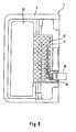
- the clamping devices 1 shown are used for fastening plates, in particular transparent glass panes 2, with a variety of additional electrical, electronic and / or electro-acoustic functions.
- Each clamping device 1 consists of at least two attachable to a plate or glass plate 2 clamping parts 3, 4, which have on their inner sides to the plate 2 abutting clamping pad 5, 6 of elastomeric material and which are clamped by at least one clamping screw 7 against each other.
- the rear in Fig. 1 clamping part 3 of this first clamping device 1 has a right angle to him base part 8 with a bore 9, by means of at least one fastening screw to a vertical or horizontal support, such as a wall, ceiling, floor, posts or the like, can be screwed.
- a vertical or horizontal support such as a wall, ceiling, floor, posts or the like
- the electrical connection 10 consists of a multi-pole terminal block 13 with a plurality of clamping bushes 14 for a plug connection with a band-shaped highly flexible multi-pole foil conductor 15 which is connected to the electrical conductor tracks 12 on the plate or glass pane 2.
- the multi-pole terminal block 13 is arranged with an electronic circuit board 16 (Fig. 7) in a rubber potting compound 17 on the base part 8 of the clamping device 1 and connected to an electrical connection line 18.
- connection line 18 is secured with a strain relief 19 in the potting compound 17 and / or on the printed circuit board 16.
- the clamping device 1 thus consists of two mutually clampable clamping jaws 3, 4, of which one (3) with the angled base part 8 and at least one opening or bore 9 for a fastening screw and a Implementation 20 is formed for the electrical connection line 18.
- the terminal block 13 forms with the printed circuit board 16, the potting compound 17, the strain relief 19 and the clamping pad 5 is a structural unit and is preferably disposed on the jaw 3 with the base part 8 in a trough-like recess 21, which up to the rear passage 20 for the electrical connection line 18 on the base part 8 extends.
- the terminal block 13 is arranged on the clamping device 1 in parallel between the base part 8 and the edge 22 of the plate to be held or glass pane 2 such that the band-shaped multi-pole foil conductor 15 can be inserted by any bends in the terminal block 13 (Fig. 7).
- the second clamping device 1 a of FIGS. 9 to 12 is a line-shaped clamping system comprising a glass clamping profile with a basic profile 3 a, preferably continuous over the length or width of the plate or glass pane 2, with a base leg 8 a for fixing the base profile 3a to a support, such as a support profile, on a wall or the like.
- the base profile 3a has a voltage applied to the plate or glass support legs 3b attached thereto clamping pads 5.
- This support leg 3b cooperates with one or more clamping plates 4a, which may be distributed over the length of the base profile 3a and with an upper support leg 4b in a grooved Longitudinal groove 3c are mounted on the base profile 3a so tiltable that they rest with a downwardly directed clamping leg 4c on the plate or glass 2 and thus they press against the support leg 3b of the base profile 3a so firmly that the plate or glass 2 is held absolutely safe.
- each Connection opening 3e is longer than the connecting element with the terminal block 13, so that a sufficient length or height tolerance in the assembly of the plate or disc 2 is made.
- a plurality of elongated connection openings 3e for the terminal block 13 are distributed such that the terminal block 13 can be mounted on the base profile 3a as needed at any desired location.
- a plurality of holes 9 for wall mounting the Profilemente are distributed in the base leg 8a.
- the terminal block 13 and the film conductor 15 are formed at least two or more poles, for example, 9-pin in both embodiments shown, but may also have significantly more poles.
Landscapes
- Engineering & Computer Science (AREA)
- Architecture (AREA)
- Civil Engineering (AREA)
- Structural Engineering (AREA)
- Microelectronics & Electronic Packaging (AREA)
- Installation Of Indoor Wiring (AREA)
- Coupling Device And Connection With Printed Circuit (AREA)
- Connection Of Plates (AREA)
Claims (8)
- Dispositif de serrage pour fixer des panneaux, en particulier des vitres transparentes, avec au moins deux pièces de serrage (3, 4; 3a, 4a) qui peuvent être montées sur le panneau (2) qui présentent, sur leurs côtés intérieurs, des rembourrages de serrage (5) en un matériau élastomère qui se posent sur le panneau (2) et qui peuvent être serrés l'un contre l'autre par au moins une vis de serrage (7), une pièce de serrage (3; 3a) ayant une pièce de base (8; 8a) qui est à angle droit par rapport à elle, pièce de base qui peut être vissée par au moins une vis de fixation à un support vertical ou horizontal tel qu'un mur, plafond, sol, montant ou équivalent et le dispositif de serrage (1; 1 a) ayant un raccord électrique (10) flexible, souple mécaniquement avec une fiche de raccordement multipolaire (11) pour des panneaux ou vitres en une ou plusieurs couches (2) avec un dispositif de conducteurs électriques (12) constitué par un ou plusieurs matériaux supports non conducteurs et plusieurs circuits imprimés électriques, caractérisé en ce que le raccord électrique (10) est constitué par une réglette de raccordement multipolaire (13) avec plusieurs douilles de serrage (14) pour une fiche de raccordement avec une piste conductive multipolaire en feuille extrêmement flexible en forme de bande (15) qui est reliée aux circuits imprimés électriques (12) sur le panneau ou la vitre (2).
- Dispositif de serrage selon la revendication 1, caractérisé en ce que la réglette de raccordement multipolaire (13) est placée avec une platine électronique de circuits imprimés (16) dans une masse de scellement en caoutchouc (17) sur la pièce de base (8; 8a) du dispositif de serrage (1; 1a) et est reliée à une conduite de raccord électrique (18).
- Dispositif de serrage selon la revendication 1 ou 2, caractérisé en ce que la conduite de raccord (18) est protégée avec une décharge de tension (19).
- Dispositif de serrage selon l'une des revendications précédentes, caractérisé en ce que le dispositif de serrage (1) est constitué par deux mâchoires de serrage (3, 4) pouvant être serrées l'une contre l'autre dont l'une (3) est configurée avec une pièce de base coudée (8) avec au moins une forure (9) pour une vis de fixation ainsi qu'un passage (20) pour la conduite de raccord électrique (18) et que la réglette de raccordement (13) forme une unité avec la platine de circuits imprimés (16), la masse de scellement (17), la décharge de tension (19) et le rembourrage de serrage (5) et est de préférence placée sur la mâchoire de serrage (3) avec la pièce de base (8) dans un évidement de type cuvette (21) qui va jusqu'au passage arrière (2)0 pour la conduite de raccord électrique (18) sur la pièce de base (8).
- Dispositif de serrage selon l'une des revendications précédentes, caractérisé en ce que la réglette de raccordement (13) est placée sur le dispositif de serrage (1) parallèlement entre la pièce de base (8) et le bord (22) du panneau ou de la vitre à maintenir (2) de telle manière que la piste conductive multipolaire en feuille en forme de bande (15) peut être emboîtée dans la réglette de raccordement (13) par des courbures quelconques.
- Dispositif de serrage selon la revendication 1, caractérisé en ce que le dispositif de serrage (1a) est constitué par un profilé de serrage de cadre en verre avec un profilé de base (3a) de préférence continu sur la longueur ou la largeur du panneau ou de la vitre (2) avec un montant de base (8a) pour la fixation du profilé de base (3a) à un support comme un profilé de support, à un mur ou équivalent et par un montant de support (3b) qui est posé contre le panneau ou la vitre avec des rembourrages de serrage (5) qui y sont fixés ainsi que des plaques de serrage (4a) qui peuvent être réparties en pouvant être fixées sur le montant de support (3b) au moyen de vis de serrage, plaques qui sont positionnées basculantes avec un montant d'appui supérieur (4b) dans une rainure longitudinale cannelée (3c) sur le profilé de base (3a) de telle manière qu'elles reposent avec un montant de serrage orienté vers le bas (4c) sur le panneau ou la vitre (2) et que la réglette de raccordement (13) est placée avec la platine de circuits imprimés (16), la masse de scellement (17) et la décharge de tension (19) sur le montant de base (8a) du profilé de base (3a) dans une rainure longitudinale située à l'extérieur (3d) avec plusieurs ouvertures de raccord allongées (3e) orientées vers le panneau ou la vitre (2) de telle manière que la réglette de raccordement (13) pénètre par les ouvertures de raccord (3e) sur le montant de base (8a) en direction du panneau ou de la vitre (2) à maintenir pour l'emboîtement avec la piste conductive multipolaire en feuille extrêmement flexible en forme de bande (15) sur le panneau ou la vitre (2).
- Dispositif de serrage selon la revendicaion 6, caractérisé en ce que plusieurs ouvertures de raccord allongées (3e) pour la réglette de raccordement (13) sont réparties sur la longueur du montant de base (8a) du profilé de base (3a) de telle manière que la réglette de raccordement (13) peut être montée sur le profilé de base (3a) tout à fait selon le besoin à n'importe quel endroit souhaité.
- Dispositif de serrage selon l'une des revendications 1 à 7, caractérisé en ce que la réglette de raccordement (13) et la piste conductive en feuille (15) sont configurées au moins bipolaires ou multipolaires.
Applications Claiming Priority (2)
| Application Number | Priority Date | Filing Date | Title |
|---|---|---|---|
| DE10132963A DE10132963C1 (de) | 2001-07-06 | 2001-07-06 | Klemmvorrichtung zum Befestigen von Platten, insbesondere Glasscheiben |
| DE10132963 | 2001-07-06 |
Publications (2)
| Publication Number | Publication Date |
|---|---|
| EP1273809A1 EP1273809A1 (fr) | 2003-01-08 |
| EP1273809B1 true EP1273809B1 (fr) | 2006-04-19 |
Family
ID=7690943
Family Applications (1)
| Application Number | Title | Priority Date | Filing Date |
|---|---|---|---|
| EP02010983A Expired - Lifetime EP1273809B1 (fr) | 2001-07-06 | 2002-05-17 | Fixation par serrage pour panneaux, notamment en verre, connections électriques inclues |
Country Status (4)
| Country | Link |
|---|---|
| EP (1) | EP1273809B1 (fr) |
| AT (1) | ATE323840T1 (fr) |
| DE (2) | DE10132963C1 (fr) |
| ES (1) | ES2261551T3 (fr) |
Cited By (1)
| Publication number | Priority date | Publication date | Assignee | Title |
|---|---|---|---|---|
| EP4159000A1 (fr) * | 2020-05-27 | 2023-04-05 | Bayerische Motoren Werke Aktiengesellschaft | Pièce de fixation pour un véhicule automobile, véhicule automobile comprenant une pièce de fixation de ce type et procédé de fabrication |
Families Citing this family (13)
| Publication number | Priority date | Publication date | Assignee | Title |
|---|---|---|---|---|
| DE10256643A1 (de) * | 2002-12-03 | 2004-06-17 | Hella Kg Hueck & Co. | Flachleiterfixierung für elektronische, elektromechanische oder elektrooptische Geräte auf Autoscheiben |
| DE102004018109B3 (de) * | 2004-04-14 | 2005-06-16 | Saint-Gobain Glass Deutschland Gmbh | Plattenelement mit einer elektrischen Leiterstruktur |
| US7700901B2 (en) | 2006-02-10 | 2010-04-20 | Radiant Glass Industries, Llc | Heated glass panels |
| US20070188843A1 (en) * | 2006-02-10 | 2007-08-16 | Radiant Glass Industries, Llc | Heated glass panel system |
| DE102007046320A1 (de) * | 2007-09-27 | 2009-04-02 | Robert Bosch Gmbh | Kontaktierungsanordnung und Kontaktierungsverfahren für Leiterbahnen von Heizungen und Antennen in Kraftfahrzeugscheiben |
| DE102013003532A1 (de) * | 2013-03-02 | 2014-09-04 | Brose Fahrzeugteile Gmbh & Co. Kommanditgesellschaft, Hallstadt | Baugruppe für ein verstellbares Fahrzeugteil |
| DE102013205733A1 (de) * | 2013-03-31 | 2014-10-02 | P.R. Agentur für transparente Kommunikation GmbH | Beschlag für ein Glaselement |
| WO2017186360A1 (fr) * | 2016-04-27 | 2017-11-02 | Saint-Gobain Glass France | Système pour le raccordement d'un corps plan à une tension d'alimentation, comprenant une unité de commande intégrée |
| US10283396B2 (en) * | 2016-06-27 | 2019-05-07 | Asm Nexx, Inc. | Workpiece holder for a wet processing system |
| DE102019212015A1 (de) * | 2019-08-09 | 2021-02-11 | Brose Fahrzeugteile Se & Co. Kommanditgesellschaft, Bamberg | Montagevorrichtung eines Fensterhebers |
| DE102019007253A1 (de) * | 2019-10-18 | 2021-04-22 | Elkamet Kunststofftechnik Gmbh | Elektrifizierte Leistenanordnung |
| RU201080U1 (ru) * | 2020-09-25 | 2020-11-26 | Акционерное общество «АВТОВАЗ» | Конструкция узла проводов обогреваемого оконного стекла транспортного средства |
| CN114892854B (zh) * | 2022-05-12 | 2023-03-21 | 江苏华发装饰有限公司 | 一种玻璃幕墙层间结构 |
Family Cites Families (8)
| Publication number | Priority date | Publication date | Assignee | Title |
|---|---|---|---|---|
| US5234358A (en) * | 1992-06-09 | 1993-08-10 | Molex Incorporated | Strain relief shell for an electrical connector |
| US5594573A (en) * | 1993-10-15 | 1997-01-14 | August; Gregg D. | Image display glasses having an LCD for displaying an image wherein the image provides for viewing by others |
| DE9318761U1 (de) * | 1993-12-08 | 1995-04-06 | SWS Gesellschaft für Glasbaubeschläge mbH, 51545 Waldbröl | Klemmvorrichtung zum Befestigen von Platten, insbesondere Glasscheiben |
| US5532436A (en) * | 1994-01-10 | 1996-07-02 | Borg-Warner Automotive, Inc. | Method of installing and holding cable sealing components into an outlet |
| US5501612A (en) * | 1994-06-17 | 1996-03-26 | The Whitaker Corporation | Low profile board-to-board electrical connector |
| DE29711973U1 (de) * | 1997-07-08 | 1998-11-05 | Firma Glas-Platz, 51580 Reichshof | Elektrische Vorrichtung, elektrisches Gerät bzw. Beleuchtungsvorrichtung |
| DE29901960U1 (de) * | 1999-02-05 | 1999-06-17 | SWS Gesellschaft für Glasbaubeschläge mbH, 51545 Waldbröl | Glasfassungsklemmprofil, insbesondere für eine hängende Halterung von Glasplatten |
| DE20107908U1 (de) * | 2001-05-10 | 2001-09-06 | Heim, Nenad, 51545 Waldbröl | Klemmvorrichtung zum Befestigen von Platten und insbesondere transparenten Glasscheiben |
-
2001
- 2001-07-06 DE DE10132963A patent/DE10132963C1/de not_active Expired - Fee Related
-
2002
- 2002-05-17 AT AT02010983T patent/ATE323840T1/de not_active IP Right Cessation
- 2002-05-17 DE DE50206444T patent/DE50206444D1/de not_active Expired - Fee Related
- 2002-05-17 ES ES02010983T patent/ES2261551T3/es not_active Expired - Lifetime
- 2002-05-17 EP EP02010983A patent/EP1273809B1/fr not_active Expired - Lifetime
Cited By (1)
| Publication number | Priority date | Publication date | Assignee | Title |
|---|---|---|---|---|
| EP4159000A1 (fr) * | 2020-05-27 | 2023-04-05 | Bayerische Motoren Werke Aktiengesellschaft | Pièce de fixation pour un véhicule automobile, véhicule automobile comprenant une pièce de fixation de ce type et procédé de fabrication |
Also Published As
| Publication number | Publication date |
|---|---|
| ES2261551T3 (es) | 2006-11-16 |
| DE10132963C1 (de) | 2002-11-14 |
| ATE323840T1 (de) | 2006-05-15 |
| DE50206444D1 (de) | 2006-05-24 |
| EP1273809A1 (fr) | 2003-01-08 |
Similar Documents
| Publication | Publication Date | Title |
|---|---|---|
| EP0924971B1 (fr) | Dispositif pour la connexion de plaques à circuit imprimé | |
| EP2112716B1 (fr) | Elément de contact pour une borne de connexion et borne de connexion | |
| EP1273809B1 (fr) | Fixation par serrage pour panneaux, notamment en verre, connections électriques inclues | |
| EP1758206A2 (fr) | Possibilité de connexion verticale dans une barette à bornes ayant des étages décalés | |
| EP0952763A2 (fr) | Boîtier pour composants électroniques | |
| DE2849418A1 (de) | Elektrischer verbinder zum verbinden einer elektronischen baueinheit mit einem traeger | |
| DE10159113A1 (de) | Leiterplattenanordnung | |
| DE4437316C2 (de) | Dezentrale Ein/Ausgabebaugruppe für elektronische Steuerungen | |
| DE2911972A1 (de) | Anschlussklemme, vorzugsweise zum einbau auf leiterplatten von gedruckten schaltungen | |
| EP0838985B1 (fr) | Dispositif pour le contact électrique de cartes de circuit au rail avant d'une baie électronique | |
| DE102004041207A1 (de) | Vorrichtung zur Verbindung von Leiterplatten | |
| DE2812332C3 (de) | Vielfachsteckverbindung für Karten mit gedruckter Schaltung | |
| DE102005036296B4 (de) | Elektrisches Kontaktierungselement | |
| DE4133846C2 (de) | Vorrichtung zur Befestigung einer Niederspannungsleuchte an einem Möbelteil | |
| DE19524850C2 (de) | Elektrische Anschlußklemme für Leiterplatten | |
| DE3028047A1 (de) | Vorrichtung zum aufbau von elektrischen schaltungen durch einstecken von elektrischen bauelementen, insbesondere elektronischer lehr- und experimentierbaukasten | |
| DE2849062C2 (fr) | ||
| DE10110367A1 (de) | Klemme mit Lichtemissionselement | |
| DE3911108A1 (de) | Elektrische anschlussklemme fuer leiterplatten | |
| EP1566864B1 (fr) | Module de prise de courant pour une tête de support de plafond médical | |
| EP1257005A1 (fr) | Dispositif de fixation de plaques en particulier des vitres transparentes | |
| DE3430849A1 (de) | Verfahren zur raeumlichen ausweitung der elektrischen verbindung zwischen den anschlusskontakten hochintegrierter elektronischer bauelemente und den kontaktstellen einer elektrischen anschlussvorrichtung auf einem bauelementetraeger | |
| DE3642342A1 (de) | Wandzentrale fuer kleine fernsprechanlagen | |
| EP1717103B1 (fr) | Rétroviseur pour véhicule automobile | |
| DE102018217104B4 (de) | Platinenanordnung sowie Platine für eine solche Platinenanordnung |
Legal Events
| Date | Code | Title | Description |
|---|---|---|---|
| PUAI | Public reference made under article 153(3) epc to a published international application that has entered the european phase |
Free format text: ORIGINAL CODE: 0009012 |
|
| AK | Designated contracting states |
Kind code of ref document: A1 Designated state(s): AT BE CH CY DE DK ES FI FR GB GR IE IT LI LU MC NL PT SE TR |
|
| AX | Request for extension of the european patent |
Free format text: AL;LT;LV;MK;RO;SI |
|
| 17P | Request for examination filed |
Effective date: 20030512 |
|
| AKX | Designation fees paid |
Designated state(s): AT BE CH CY DE DK ES FI FR GB GR IE IT LI LU MC NL PT SE TR |
|
| 17Q | First examination report despatched |
Effective date: 20050506 |
|
| GRAP | Despatch of communication of intention to grant a patent |
Free format text: ORIGINAL CODE: EPIDOSNIGR1 |
|
| GRAS | Grant fee paid |
Free format text: ORIGINAL CODE: EPIDOSNIGR3 |
|
| GRAA | (expected) grant |
Free format text: ORIGINAL CODE: 0009210 |
|
| AK | Designated contracting states |
Kind code of ref document: B1 Designated state(s): AT BE CH CY DE DK ES FI FR GB GR IE IT LI LU MC NL PT SE TR |
|
| PG25 | Lapsed in a contracting state [announced via postgrant information from national office to epo] |
Ref country code: IE Free format text: LAPSE BECAUSE OF FAILURE TO SUBMIT A TRANSLATION OF THE DESCRIPTION OR TO PAY THE FEE WITHIN THE PRESCRIBED TIME-LIMIT Effective date: 20060419 Ref country code: FI Free format text: LAPSE BECAUSE OF FAILURE TO SUBMIT A TRANSLATION OF THE DESCRIPTION OR TO PAY THE FEE WITHIN THE PRESCRIBED TIME-LIMIT Effective date: 20060419 |
|
| REG | Reference to a national code |
Ref country code: GB Ref legal event code: FG4D Free format text: NOT ENGLISH |
|
| PGFP | Annual fee paid to national office [announced via postgrant information from national office to epo] |
Ref country code: AT Payment date: 20060518 Year of fee payment: 5 Ref country code: FR Payment date: 20060518 Year of fee payment: 5 |
|
| PGFP | Annual fee paid to national office [announced via postgrant information from national office to epo] |
Ref country code: CH Payment date: 20060523 Year of fee payment: 5 |
|
| PGFP | Annual fee paid to national office [announced via postgrant information from national office to epo] |
Ref country code: NL Payment date: 20060524 Year of fee payment: 5 |
|
| REF | Corresponds to: |
Ref document number: 50206444 Country of ref document: DE Date of ref document: 20060524 Kind code of ref document: P |
|
| PGFP | Annual fee paid to national office [announced via postgrant information from national office to epo] |
Ref country code: ES Payment date: 20060525 Year of fee payment: 5 |
|
| PG25 | Lapsed in a contracting state [announced via postgrant information from national office to epo] |
Ref country code: MC Free format text: LAPSE BECAUSE OF NON-PAYMENT OF DUE FEES Effective date: 20060531 |
|
| PGFP | Annual fee paid to national office [announced via postgrant information from national office to epo] |
Ref country code: BE Payment date: 20060531 Year of fee payment: 5 Ref country code: IT Payment date: 20060531 Year of fee payment: 5 |
|
| REG | Reference to a national code |
Ref country code: IE Ref legal event code: FG4D Free format text: LANGUAGE OF EP DOCUMENT: GERMAN |
|
| PGFP | Annual fee paid to national office [announced via postgrant information from national office to epo] |
Ref country code: GB Payment date: 20060606 Year of fee payment: 5 |
|
| REG | Reference to a national code |
Ref country code: CH Ref legal event code: NV Representative=s name: ZIMMERLI, WAGNER & PARTNER AG |
|
| GBT | Gb: translation of ep patent filed (gb section 77(6)(a)/1977) |
Effective date: 20060605 |
|
| PG25 | Lapsed in a contracting state [announced via postgrant information from national office to epo] |
Ref country code: SE Free format text: LAPSE BECAUSE OF FAILURE TO SUBMIT A TRANSLATION OF THE DESCRIPTION OR TO PAY THE FEE WITHIN THE PRESCRIBED TIME-LIMIT Effective date: 20060719 Ref country code: DK Free format text: LAPSE BECAUSE OF FAILURE TO SUBMIT A TRANSLATION OF THE DESCRIPTION OR TO PAY THE FEE WITHIN THE PRESCRIBED TIME-LIMIT Effective date: 20060719 |
|
| PGFP | Annual fee paid to national office [announced via postgrant information from national office to epo] |
Ref country code: DE Payment date: 20060728 Year of fee payment: 5 |
|
| PG25 | Lapsed in a contracting state [announced via postgrant information from national office to epo] |
Ref country code: PT Free format text: LAPSE BECAUSE OF FAILURE TO SUBMIT A TRANSLATION OF THE DESCRIPTION OR TO PAY THE FEE WITHIN THE PRESCRIBED TIME-LIMIT Effective date: 20060919 |
|
| ET | Fr: translation filed | ||
| REG | Reference to a national code |
Ref country code: IE Ref legal event code: FD4D |
|
| REG | Reference to a national code |
Ref country code: ES Ref legal event code: FG2A Ref document number: 2261551 Country of ref document: ES Kind code of ref document: T3 |
|
| PLBE | No opposition filed within time limit |
Free format text: ORIGINAL CODE: 0009261 |
|
| STAA | Information on the status of an ep patent application or granted ep patent |
Free format text: STATUS: NO OPPOSITION FILED WITHIN TIME LIMIT |
|
| 26N | No opposition filed |
Effective date: 20070122 |
|
| BERE | Be: lapsed |
Owner name: *SWS G.- FUR GLASBAUBESCHLAGE M.B.H. Effective date: 20070531 |
|
| REG | Reference to a national code |
Ref country code: CH Ref legal event code: PL |
|
| GBPC | Gb: european patent ceased through non-payment of renewal fee |
Effective date: 20070517 |
|
| PG25 | Lapsed in a contracting state [announced via postgrant information from national office to epo] |
Ref country code: NL Free format text: LAPSE BECAUSE OF NON-PAYMENT OF DUE FEES Effective date: 20071201 |
|
| NLV4 | Nl: lapsed or anulled due to non-payment of the annual fee |
Effective date: 20071201 |
|
| PG25 | Lapsed in a contracting state [announced via postgrant information from national office to epo] |
Ref country code: AT Free format text: LAPSE BECAUSE OF NON-PAYMENT OF DUE FEES Effective date: 20070517 Ref country code: LI Free format text: LAPSE BECAUSE OF NON-PAYMENT OF DUE FEES Effective date: 20070531 Ref country code: CH Free format text: LAPSE BECAUSE OF NON-PAYMENT OF DUE FEES Effective date: 20070531 |
|
| REG | Reference to a national code |
Ref country code: FR Ref legal event code: ST Effective date: 20080131 |
|
| PG25 | Lapsed in a contracting state [announced via postgrant information from national office to epo] |
Ref country code: BE Free format text: LAPSE BECAUSE OF NON-PAYMENT OF DUE FEES Effective date: 20070531 |
|
| PG25 | Lapsed in a contracting state [announced via postgrant information from national office to epo] |
Ref country code: GR Free format text: LAPSE BECAUSE OF FAILURE TO SUBMIT A TRANSLATION OF THE DESCRIPTION OR TO PAY THE FEE WITHIN THE PRESCRIBED TIME-LIMIT Effective date: 20060720 Ref country code: DE Free format text: LAPSE BECAUSE OF NON-PAYMENT OF DUE FEES Effective date: 20071201 |
|
| PG25 | Lapsed in a contracting state [announced via postgrant information from national office to epo] |
Ref country code: GB Free format text: LAPSE BECAUSE OF NON-PAYMENT OF DUE FEES Effective date: 20070517 |
|
| PG25 | Lapsed in a contracting state [announced via postgrant information from national office to epo] |
Ref country code: TR Free format text: LAPSE BECAUSE OF FAILURE TO SUBMIT A TRANSLATION OF THE DESCRIPTION OR TO PAY THE FEE WITHIN THE PRESCRIBED TIME-LIMIT Effective date: 20060419 Ref country code: LU Free format text: LAPSE BECAUSE OF NON-PAYMENT OF DUE FEES Effective date: 20060517 Ref country code: FR Free format text: LAPSE BECAUSE OF NON-PAYMENT OF DUE FEES Effective date: 20070531 |
|
| REG | Reference to a national code |
Ref country code: ES Ref legal event code: FD2A Effective date: 20070518 |
|
| PG25 | Lapsed in a contracting state [announced via postgrant information from national office to epo] |
Ref country code: ES Free format text: LAPSE BECAUSE OF NON-PAYMENT OF DUE FEES Effective date: 20070518 |
|
| PG25 | Lapsed in a contracting state [announced via postgrant information from national office to epo] |
Ref country code: CY Free format text: LAPSE BECAUSE OF FAILURE TO SUBMIT A TRANSLATION OF THE DESCRIPTION OR TO PAY THE FEE WITHIN THE PRESCRIBED TIME-LIMIT Effective date: 20060419 |
|
| PG25 | Lapsed in a contracting state [announced via postgrant information from national office to epo] |
Ref country code: IT Free format text: LAPSE BECAUSE OF NON-PAYMENT OF DUE FEES Effective date: 20070517 |