EP1274103B1 - Ecran pour réduire le flux de fuite ou le champ de dispersion produit par un objet - Google Patents
Ecran pour réduire le flux de fuite ou le champ de dispersion produit par un objet Download PDFInfo
- Publication number
- EP1274103B1 EP1274103B1 EP02012797A EP02012797A EP1274103B1 EP 1274103 B1 EP1274103 B1 EP 1274103B1 EP 02012797 A EP02012797 A EP 02012797A EP 02012797 A EP02012797 A EP 02012797A EP 1274103 B1 EP1274103 B1 EP 1274103B1
- Authority
- EP
- European Patent Office
- Prior art keywords
- wall
- shielding
- shielding according
- material layer
- lid
- Prior art date
- Legal status (The legal status is an assumption and is not a legal conclusion. Google has not performed a legal analysis and makes no representation as to the accuracy of the status listed.)
- Expired - Lifetime
Links
- 230000004907 flux Effects 0.000 title description 3
- 239000000463 material Substances 0.000 claims abstract description 19
- 229910052782 aluminium Inorganic materials 0.000 claims description 5
- XAGFODPZIPBFFR-UHFFFAOYSA-N aluminium Chemical compound [Al] XAGFODPZIPBFFR-UHFFFAOYSA-N 0.000 claims description 5
- 238000010276 construction Methods 0.000 claims description 4
- 230000005855 radiation Effects 0.000 claims description 4
- 230000035699 permeability Effects 0.000 claims description 3
- 229910000838 Al alloy Inorganic materials 0.000 claims description 2
- 229910052751 metal Inorganic materials 0.000 claims description 2
- 239000002184 metal Substances 0.000 claims description 2
- 230000003068 static effect Effects 0.000 claims description 2
- 239000004411 aluminium Substances 0.000 claims 2
- 230000004308 accommodation Effects 0.000 claims 1
- 230000002411 adverse Effects 0.000 claims 1
- 238000010292 electrical insulation Methods 0.000 claims 1
- 238000001816 cooling Methods 0.000 abstract description 3
- 230000005672 electromagnetic field Effects 0.000 description 4
- 230000005865 ionizing radiation Effects 0.000 description 4
- 238000009434 installation Methods 0.000 description 3
- 238000012423 maintenance Methods 0.000 description 2
- 230000009467 reduction Effects 0.000 description 2
- 238000009420 retrofitting Methods 0.000 description 2
- 238000004804 winding Methods 0.000 description 2
- 229910000831 Steel Inorganic materials 0.000 description 1
- 230000015572 biosynthetic process Effects 0.000 description 1
- 210000004556 brain Anatomy 0.000 description 1
- 230000000747 cardiac effect Effects 0.000 description 1
- 238000005253 cladding Methods 0.000 description 1
- 239000004020 conductor Substances 0.000 description 1
- 230000008602 contraction Effects 0.000 description 1
- 230000001419 dependent effect Effects 0.000 description 1
- 230000000694 effects Effects 0.000 description 1
- 230000007613 environmental effect Effects 0.000 description 1
- 238000002474 experimental method Methods 0.000 description 1
- 239000011796 hollow space material Substances 0.000 description 1
- 230000006698 induction Effects 0.000 description 1
- 238000009413 insulation Methods 0.000 description 1
- 239000002085 irritant Substances 0.000 description 1
- 231100000021 irritant Toxicity 0.000 description 1
- 230000005415 magnetization Effects 0.000 description 1
- 238000005259 measurement Methods 0.000 description 1
- 210000003205 muscle Anatomy 0.000 description 1
- 210000004165 myocardium Anatomy 0.000 description 1
- 210000005036 nerve Anatomy 0.000 description 1
- 230000008521 reorganization Effects 0.000 description 1
- 238000012552 review Methods 0.000 description 1
- 239000010959 steel Substances 0.000 description 1
- 238000012549 training Methods 0.000 description 1
Images


Classifications
-
- H—ELECTRICITY
- H01—ELECTRIC ELEMENTS
- H01F—MAGNETS; INDUCTANCES; TRANSFORMERS; SELECTION OF MATERIALS FOR THEIR MAGNETIC PROPERTIES
- H01F27/00—Details of transformers or inductances, in general
- H01F27/34—Special means for preventing or reducing unwanted electric or magnetic effects, e.g. no-load losses, reactive currents, harmonics, oscillations, leakage fields
- H01F27/346—Preventing or reducing leakage fields
-
- H—ELECTRICITY
- H01—ELECTRIC ELEMENTS
- H01F—MAGNETS; INDUCTANCES; TRANSFORMERS; SELECTION OF MATERIALS FOR THEIR MAGNETIC PROPERTIES
- H01F27/00—Details of transformers or inductances, in general
- H01F27/34—Special means for preventing or reducing unwanted electric or magnetic effects, e.g. no-load losses, reactive currents, harmonics, oscillations, leakage fields
- H01F27/36—Electric or magnetic shields or screens
- H01F27/361—Electric or magnetic shields or screens made of combinations of electrically conductive material and ferromagnetic material
-
- H—ELECTRICITY
- H01—ELECTRIC ELEMENTS
- H01F—MAGNETS; INDUCTANCES; TRANSFORMERS; SELECTION OF MATERIALS FOR THEIR MAGNETIC PROPERTIES
- H01F27/00—Details of transformers or inductances, in general
- H01F27/34—Special means for preventing or reducing unwanted electric or magnetic effects, e.g. no-load losses, reactive currents, harmonics, oscillations, leakage fields
- H01F27/36—Electric or magnetic shields or screens
Definitions
- the present invention relates to a shield for receiving at least one non-ionizing radiation or non-ionizing field generating object. In particular, it is about the protection against electromagnetic fields in the field of energy systems.
- FR 2 759 488 A1 a device for reducing the Foucault currents, or eddy currents, and a corresponding transformer is described.
- the transformer has three windings surrounding the core. To reduce Foucault currents, the electromagnetic field emanating from the transformer is superimposed by a circuit surrounding these windings. This device is not directly comparable to the subject matter of the present invention.
- the invention has as its object to provide a shield for receiving at least one non-ionizing radiation or a non-ionizing field generating object that allows compliance with the limits.
- the inventive shielding in the field of energy systems such as transformers, an effective, yet achievable with relatively little constructive and financial effort achievable protection against electromagnetic fields created.
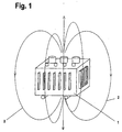
- FIG. 1 the course of the field lines 2 of an electromagnetic interference field can be seen on the example of a transformer 1 shown schematically.
- an arrangement of the transformer 1 in a shielding housing would be the best solution. Since this is not possible for various reasons, on the one hand because of the circulation of air to be cooled by heat, on the other hand, because of the accessibility of the transformer 1, previously reached the mentioned, unsatisfactory and not sufficient wall covering the room or the building of the network station.
- the transformer 1 is arranged in a specially shaped and constructed shielding 3. From the basic idea, preferably two rectangular intersecting tube section-like elements 4 and 5 are arranged with approximately rectangular cross-section. Seen from above and from below, this arrangement of the tube-section-like elements 4 and 5 forms a cross, more precisely a Swiss cross.
- the transformer 1 is arranged in the center of this three-dimensional shield 3, standing on its bottom 6. It goes without saying that in the crossing or overlapping area in the bottom 6 and in the ceiling 7 of the two pipe section-like. Elements 4 and 5 no Wandaufdoppelung the shield 3 must be given. Rather, here the wall of the shield 3 is exactly the same as in the other parts.
- the shield 3 looks as if it were formed from two approximately U-shaped cross-section elements 4 and 5, which converge at right angles in the area of the ceiling 7. So it is either only a rectangular ceiling 7, with it outgoing, in cross-section L-shaped wall parts 14, 15, 16 and 17 available, the short L-leg rests against one edge of the ceiling 7, or both a ceiling 7 as also a bottom 6, with these connecting, in cross-section C-shaped wall parts 14, 15, 16 and 17.
- the four corners 8, 9, 10 and 11 of the shield 3 remain open in any case, which should preferably be dimensioned so in that at least the region lying directly in front of the cooling ribs 12 and 13 of the transformer 1 is covered by a strip-shaped wall part 14, 15, 16 and 17.
- the wall width 18 of one of these strip-shaped wall parts 14-17 is preferably about 100 cm.
- the open construction of the shield 3 also brings a whole series of advantages.
- the transformer 1 is for the maintenance personnel from all four corners 8 - 11 forth at any time easily accessible without shielding or trim parts would be dismounted.
- Fig. 3 the rational shield of several juxtaposed transformers 1 is shown.
- a single, expanded shielding 19 can be provided, without an intermediate wall between the individual transformers 1, but only with a first tube-section-like element 20 widened in cross-section and an additional tube-section-like element 22 for the second transformer 1.
- This expanded shielding 19 thus has , From the idea, three pipe-section-like or optionally three in cross-section U-shaped elements 20, 21 and 22 on.
- FIG. 4 The wall structure of the wall parts 14-17 and the ceiling 7 and possibly the bottom 6 of the shield 3 or 19 is shown in FIG. 4 in several parts.
- a first wall 24 is provided, preferably consisting of several layers of a ⁇ m metal.
- This first, inner wall 24, or the material attached closer to the source of interference, must have the highest possible magnetic conductivity.
- a high permeability, or a high initial magnetization is important.
- the initial permeability ⁇ 4 is preferably> 1000.
- a second wall 26 is present, for example made of aluminum or of an aluminum alloy. This second wall 26 must have the highest possible electrical conductivity, preferably Y> 30 m / ⁇ mm 2 .
- the magnetically conductive layer and the electrically conductive material are electrically isolated from each other.
- the two walls 24 and 26 are spaced from each other, forming a hollow space 27.
- This insulating gap is important on the one hand for the efficiency of the shield.
- the profiles 28 of a support structure can be arranged, which gives the shield 3 and 19, the required static stability It is important to ensure that the insulation between the two walls 24 and 26 is not affected by the support structure , For this purpose, it may already be sufficient for the profiles 28 to consist of an anodized aluminum.
- the walls 24 and 26 can be bolted to the profiles 28.
- the edges can also be closed so that the profiles 28 of an assembled shield 3 or 19 are not visible. Total results Not only a very effective and practical, but also a shapely construction.
- the described shielding 3 or 19 can be used not only in transformers 1 for which it is especially designed, but also in other objects which generate non-ionizing radiation or non-ionizing field, e.g. for control cabinets or for low-voltage distribution as well as for cable ducts, cable ducts or cable trenches.
- the shield 19 may be e.g. be stretched according to the embodiment of FIG. 3.
- the shield 3 or 19 in detail differently than shown and described previously form.
- the ceiling 7 or possibly a partial ceiling covering the space can for example also be formed from mutually directed legs of L-shaped or C-shaped wall parts 14-17.
- the ceiling 7 and possibly the bottom 6 may be rectangular instead of cross-shaped, so that the area of the open corners 8 - 11 is covered and is e.g. gives a cube-like body.
- the wall parts 14 - 17 could also be inclined, up to the formation of a pyramid.
- the outside wall 26 could also be designed as a multilayer.
- the wall parts 14 - 17 and the ceiling 7 could also be fixed so that they can be disassembled quickly for maintenance purposes.
Landscapes
- Engineering & Computer Science (AREA)
- Power Engineering (AREA)
- Shielding Devices Or Components To Electric Or Magnetic Fields (AREA)
- X-Ray Techniques (AREA)
- Laminated Bodies (AREA)
- Application Of Or Painting With Fluid Materials (AREA)
Claims (19)
- Blindage (3, 19) pour la réception d'au moins un objet générant un rayonnement non ionisant ou un champ non ionisant, constitué d'une structure comportant au moins deux éléments de paroi (14, 15, 16, 17), l'espace situé entre ces deux éléments de paroi (14, 15, 16, 17) étant au moins partiellement recouvert, caractérisé en ce que dans la région d'au moins une partie des angles (8, 9, 10, 11) sont prévus des orifices ou en ce que lesdits angles (8, 9, 10, 11) sont ouverts.
- Blindage selon la revendication 2, caractérisé par des éléments de paroi à section transversale en forme de L (14, 15, 16, 17), l'une des branches, par exemple la branche longue en forme de L formant une paroi orientée de préférence à la verticale et l'autre, par exemple la branche courte en forme de L étant disposée dans le haut et orientée vers l'intérieur de façon à former au moins une partie d'une couverture et/ou à s'appliquer contre ou sur un bord d'une couverture (7).
- Blindage selon la revendication 1 ou 2, caractérisé par des éléments de paroi à section transversale en forme de C (14, 15, 16, 17), dont les branches en C saillant librement sont dirigées vers l'intérieur et débouchent par exemple chacune dans un fond commun (6) et dans une couverture commune (7) ou forment un tel fond ou une telle couverture.
- Blindage selon l'une quelconque des revendications 1 à 3, caractérisé en ce que sa structure dans la région du fond (6) et/ou dans la région de la couverture (7) forme une croix, vue par le bas et/ou vue par le haut.
- Blindage selon l'une quelconque des revendications 1 à 4, caractérisé en ce qu'il présente soit deux éléments perpendiculaires du type de tronçons de tubes (4, 5), qui sont disposés de préférence de façon concentrique ou deux éléments à section transversale approximativement en forme de U.
- Blindage selon l'une quelconque des revendications 1 à 5 pour la réception de plusieurs objets situés côte à côte, générant un rayonnement non ionisant, par exemple des transformateurs (1), caractérisé en ce que sur au moins un côté du blindage (19) se trouvent au moins deux éléments de paroi disposés côte à côte à distance, entre lesquels se trouve une ouverture sur l'intérieur du blindage (19).
- Blindage selon la revendication 6, caractérisé par un premier élément du type d'un tronçon de tube (20) et par au moins deux éléments supplémentaires du type d'un tronçon de tube (21, 22), placés à la perpendiculaire de ce premier élément (20).
- Blindage selon la revendication 6, caractérisé par un premier élément (20) à section transversale en forme de U et par au moins deux éléments supplémentaires (21, 22) à section transversale également en forme de U, qui dans la région de la couverture du blindage (19) rejoignent le premier élément (20) à angle droit, par leur branche centrale en forme de U.
- Blindage selon l'une quelconque des revendications 1 à 8, caractérisé en ce que la structure des éléments de paroi (14, 15, 16, 17) et de la couverture (7) et tout au plus d'un fond (6) comporte vers la face intérieure (23) au moins une couche métallique à haute conductibilité magnétique et en ce qu'au moins une couche de matériau à haute conductibilité électrique est placé en direction de la face extérieure (25).
- Blindage selon la revendication 9, caractérisé en ce que la couche de matériau à haute conductibilité magnétique et la couche de matériau à haute conductibilité électrique sont disposées de façon à être électriquement isolées l'une par rapport à l'autre.
- Blindage selon la revendication 10, caractérisé en ce que la structure des éléments de paroi (14, 15, 16, 17) et de la couverture (7) et tout au plus d'un fond (6) est à paroi multiples, par exemple à double paroi, les parois individuelles (24, 26) étant disposées à distance l'une par rapport à l'autre en formant un espace intermédiaire (27) et la première paroi (24) faisant preuve d'une haute conductibilité magnétique ou étant munie d'un couche de matériau correspondante et la deuxième paroi (26) faisant preuve d'une haute conductibilité électrique ou étant munie d'une couche de matériau correspondante.
- Blindage selon l'une quelconque des revendications 9 à 11, caractérisé en ce que la perméabilité initiale de la couche de matériau ou de la paroi (24) présente une haute conductibilité magnétique µ4 > 1000.
- Blindage selon l'une quelconque des revendications 9 à 12, caractérisé en ce que la conductibilité électrique de la couche de matériau ou de la paroi (26) présente une haute conductibilité électrique Y > 30m/Ωmm2.
- Blindage selon l'une quelconque des revendications 11 à 13, caractérisé en ce qu'au moins sur la face intérieure (23), c'est-à-dire vers l'un des objets générant des rayonnement non ionisants, par exemple le transformateur (1) se trouve une paroi (24) conçue à couches multiples.
- Blindage selon la revendication 14, caractérisé en ce que la paroi (24) située sur la face intérieure (23) est en matériau µm ou comporte une telle couche de matériau.
- Blindage selon l'une quelconque des revendications 11 à 15, caractérisé en ce qu'une première paroi (24) à couches multiples se trouve sur la face intérieure (23) et une deuxième paroi (26) en une seule couche de matériau, par exemple en aluminium ou en un alliage d'aluminium se trouve sur la face extérieure (25).
- Blindage selon l'une quelconque des revendications 11 à 16, caractérisé en ce que des profilés d'une structure porteuse conférant au blindage (3, 19) sa stabilité statique sont disposés dans l'espace intermédiaire (27) entre deux parois (24, 26).
- Blindage selon la revendication 17, caractérisé en ce que les profilés (28) sont en un matériau qui n'altère par l'isolation électrique entre les parois (24, 26), par exemple en aluminium éloxé.
- Blindage selon l'une quelconque des revendications 1 à 18, caractérisé en ce que les éléments de paroi (14, 15, 16, 17) sont conçus sous la forme de bandes et ont une épaisseur de paroi (18) de 80 à 120 cm, de préférence de 100 cm.
Applications Claiming Priority (2)
| Application Number | Priority Date | Filing Date | Title |
|---|---|---|---|
| CH12162001 | 2001-07-03 | ||
| CH01216/01A CH695643A5 (de) | 2001-07-03 | 2001-07-03 | Abschirmung zur Aufnahme mindestens eines eine nichtionisierende Strahlung oder ein nichtionisierendes Feld erzeugenden Objektes. |
Publications (2)
| Publication Number | Publication Date |
|---|---|
| EP1274103A1 EP1274103A1 (fr) | 2003-01-08 |
| EP1274103B1 true EP1274103B1 (fr) | 2006-03-22 |
Family
ID=4563455
Family Applications (1)
| Application Number | Title | Priority Date | Filing Date |
|---|---|---|---|
| EP02012797A Expired - Lifetime EP1274103B1 (fr) | 2001-07-03 | 2002-06-10 | Ecran pour réduire le flux de fuite ou le champ de dispersion produit par un objet |
Country Status (4)
| Country | Link |
|---|---|
| EP (1) | EP1274103B1 (fr) |
| AT (1) | ATE321348T1 (fr) |
| CH (1) | CH695643A5 (fr) |
| DE (1) | DE50206113D1 (fr) |
Families Citing this family (1)
| Publication number | Priority date | Publication date | Assignee | Title |
|---|---|---|---|---|
| DE102006024354A1 (de) * | 2006-05-24 | 2007-11-29 | Nkt Cables Gmbh | Behälter zur Schirmung von Magnetfeldern niedriger Frequenz |
Family Cites Families (3)
| Publication number | Priority date | Publication date | Assignee | Title |
|---|---|---|---|---|
| AT328551B (de) * | 1974-04-12 | 1976-03-25 | Siemens Ag Oesterreich | Breitbandabschirmung gegen magnetischen streufluss |
| JPH04158505A (ja) * | 1990-10-23 | 1992-06-01 | Toshiba Corp | リアクトル装置 |
| JP3566481B2 (ja) * | 1997-02-07 | 2004-09-15 | 株式会社日立製作所 | 渦電流シールド装置および三相変圧器 |
-
2001
- 2001-07-03 CH CH01216/01A patent/CH695643A5/de not_active IP Right Cessation
-
2002
- 2002-06-10 EP EP02012797A patent/EP1274103B1/fr not_active Expired - Lifetime
- 2002-06-10 AT AT02012797T patent/ATE321348T1/de not_active IP Right Cessation
- 2002-06-10 DE DE50206113T patent/DE50206113D1/de not_active Expired - Lifetime
Also Published As
| Publication number | Publication date |
|---|---|
| EP1274103A1 (fr) | 2003-01-08 |
| ATE321348T1 (de) | 2006-04-15 |
| CH695643A5 (de) | 2006-07-14 |
| DE50206113D1 (de) | 2006-05-11 |
Similar Documents
| Publication | Publication Date | Title |
|---|---|---|
| EP2428967B1 (fr) | Enroulement de transformateur | |
| DE69411907T2 (de) | Geschirmte hochspannungsfreileitung | |
| EP3304097B1 (fr) | Transformateur de courant à flux nul | |
| DE102017106104A1 (de) | Auszugsführung und Mikrowellengargerät oder industrieller Wärmeofen mit einer Auszugsführung | |
| EP0403788A2 (fr) | Agencement de détecteur à bobines | |
| EP3001435B1 (fr) | Noyau de transformateur à sec | |
| WO2009046733A1 (fr) | Corps d'enroulement électrique et transformateur à refroidissement forcé | |
| EP2593999A1 (fr) | Coffret de barres conductrices et système de canalisations préfabriquées comprenant un coffret de barres conductrices | |
| DE19747622A1 (de) | Dämmplatten mit einer Abschirmung gegen elektromagnetische Felder | |
| EP1274103B1 (fr) | Ecran pour réduire le flux de fuite ou le champ de dispersion produit par un objet | |
| DE202013007444U1 (de) | Elektronikmodul und modulares Elektroniksystem | |
| DE10238521B4 (de) | Wicklungsanordnung | |
| DE69934869T2 (de) | Faraday-Käfig für Anwendungen auf dem Gebiet der magnetischen Kernresonanz | |
| WO2018033451A1 (fr) | Bobine de puissance symétrique à multiples phases | |
| DE2802507B2 (de) | Mit einem Abschirmgehäuse ausgestattetes Hohlraumresonator-Magnetron | |
| DE4026403C2 (de) | Wandsystem mit Abschirmung gegen elektromagnetische Felder und Strahlen | |
| DE202016104469U1 (de) | Spannungsgeführter Stromrichter mit einem Ferritabschwächer | |
| DE19527974C2 (de) | Magnetische Abschirmung von elektrischen Einrichtungen | |
| CH695818A5 (de) | Verfahren zum Abschirmen mindestens eines Nieder- oder Mittelspannungsverteilers und Abschirmung zur Ausführung dieses Verfahrens. | |
| DE3629310C2 (fr) | ||
| DE19713679C2 (de) | Niederspannungs-Verteilanordnung | |
| EP1480504A1 (fr) | Dispositif de blindage | |
| DE4108251A1 (de) | Emv-pruefkammer (elektromagnetische vertraeglichkeitspruefung) | |
| CH694716A5 (de) | Freileitung fuer die Wechselstromversorgung. | |
| DE878983C (de) | Isoliertransformator fuer hohe Spannungen |
Legal Events
| Date | Code | Title | Description |
|---|---|---|---|
| PUAI | Public reference made under article 153(3) epc to a published international application that has entered the european phase |
Free format text: ORIGINAL CODE: 0009012 |
|
| AK | Designated contracting states |
Kind code of ref document: A1 Designated state(s): AT BE CH CY DE DK ES FI FR GB GR IE IT LI LU MC NL PT SE TR |
|
| AX | Request for extension of the european patent |
Free format text: AL;LT;LV;MK;RO;SI |
|
| 17P | Request for examination filed |
Effective date: 20030626 |
|
| AKX | Designation fees paid |
Designated state(s): AT BE CH CY DE DK ES FI FR GB GR IE IT LI LU MC NL PT SE TR |
|
| GRAP | Despatch of communication of intention to grant a patent |
Free format text: ORIGINAL CODE: EPIDOSNIGR1 |
|
| GRAS | Grant fee paid |
Free format text: ORIGINAL CODE: EPIDOSNIGR3 |
|
| GRAA | (expected) grant |
Free format text: ORIGINAL CODE: 0009210 |
|
| AK | Designated contracting states |
Kind code of ref document: B1 Designated state(s): AT BE CH CY DE DK ES FI FR GB GR IE IT LI LU MC NL PT SE TR |
|
| PG25 | Lapsed in a contracting state [announced via postgrant information from national office to epo] |
Ref country code: NL Free format text: LAPSE BECAUSE OF FAILURE TO SUBMIT A TRANSLATION OF THE DESCRIPTION OR TO PAY THE FEE WITHIN THE PRESCRIBED TIME-LIMIT Effective date: 20060322 Ref country code: GB Free format text: LAPSE BECAUSE OF FAILURE TO SUBMIT A TRANSLATION OF THE DESCRIPTION OR TO PAY THE FEE WITHIN THE PRESCRIBED TIME-LIMIT Effective date: 20060322 Ref country code: IE Free format text: LAPSE BECAUSE OF FAILURE TO SUBMIT A TRANSLATION OF THE DESCRIPTION OR TO PAY THE FEE WITHIN THE PRESCRIBED TIME-LIMIT Effective date: 20060322 |
|
| REG | Reference to a national code |
Ref country code: GB Ref legal event code: FG4D Free format text: NOT ENGLISH |
|
| REG | Reference to a national code |
Ref country code: CH Ref legal event code: EP |
|
| REG | Reference to a national code |
Ref country code: IE Ref legal event code: FG4D Free format text: LANGUAGE OF EP DOCUMENT: GERMAN |
|
| REF | Corresponds to: |
Ref document number: 50206113 Country of ref document: DE Date of ref document: 20060511 Kind code of ref document: P |
|
| REG | Reference to a national code |
Ref country code: CH Ref legal event code: NV Representative=s name: PA ALDO ROEMPLER |
|
| PG25 | Lapsed in a contracting state [announced via postgrant information from national office to epo] |
Ref country code: SE Free format text: LAPSE BECAUSE OF FAILURE TO SUBMIT A TRANSLATION OF THE DESCRIPTION OR TO PAY THE FEE WITHIN THE PRESCRIBED TIME-LIMIT Effective date: 20060622 Ref country code: DK Free format text: LAPSE BECAUSE OF FAILURE TO SUBMIT A TRANSLATION OF THE DESCRIPTION OR TO PAY THE FEE WITHIN THE PRESCRIBED TIME-LIMIT Effective date: 20060622 |
|
| PG25 | Lapsed in a contracting state [announced via postgrant information from national office to epo] |
Ref country code: BE Free format text: LAPSE BECAUSE OF NON-PAYMENT OF DUE FEES Effective date: 20060630 Ref country code: MC Free format text: LAPSE BECAUSE OF NON-PAYMENT OF DUE FEES Effective date: 20060630 |
|
| PG25 | Lapsed in a contracting state [announced via postgrant information from national office to epo] |
Ref country code: ES Free format text: LAPSE BECAUSE OF FAILURE TO SUBMIT A TRANSLATION OF THE DESCRIPTION OR TO PAY THE FEE WITHIN THE PRESCRIBED TIME-LIMIT Effective date: 20060703 |
|
| PG25 | Lapsed in a contracting state [announced via postgrant information from national office to epo] |
Ref country code: PT Free format text: LAPSE BECAUSE OF FAILURE TO SUBMIT A TRANSLATION OF THE DESCRIPTION OR TO PAY THE FEE WITHIN THE PRESCRIBED TIME-LIMIT Effective date: 20060822 |
|
| NLV1 | Nl: lapsed or annulled due to failure to fulfill the requirements of art. 29p and 29m of the patents act | ||
| ET | Fr: translation filed | ||
| GBV | Gb: ep patent (uk) treated as always having been void in accordance with gb section 77(7)/1977 [no translation filed] |
Effective date: 20060322 |
|
| REG | Reference to a national code |
Ref country code: IE Ref legal event code: FD4D |
|
| PLBE | No opposition filed within time limit |
Free format text: ORIGINAL CODE: 0009261 |
|
| STAA | Information on the status of an ep patent application or granted ep patent |
Free format text: STATUS: NO OPPOSITION FILED WITHIN TIME LIMIT |
|
| 26N | No opposition filed |
Effective date: 20061227 |
|
| BERE | Be: lapsed |
Owner name: CFW EMV-CONSULTING A.G. Effective date: 20060630 |
|
| PG25 | Lapsed in a contracting state [announced via postgrant information from national office to epo] |
Ref country code: GR Free format text: LAPSE BECAUSE OF FAILURE TO SUBMIT A TRANSLATION OF THE DESCRIPTION OR TO PAY THE FEE WITHIN THE PRESCRIBED TIME-LIMIT Effective date: 20060623 |
|
| PG25 | Lapsed in a contracting state [announced via postgrant information from national office to epo] |
Ref country code: FI Free format text: LAPSE BECAUSE OF FAILURE TO SUBMIT A TRANSLATION OF THE DESCRIPTION OR TO PAY THE FEE WITHIN THE PRESCRIBED TIME-LIMIT Effective date: 20060322 |
|
| PG25 | Lapsed in a contracting state [announced via postgrant information from national office to epo] |
Ref country code: TR Free format text: LAPSE BECAUSE OF FAILURE TO SUBMIT A TRANSLATION OF THE DESCRIPTION OR TO PAY THE FEE WITHIN THE PRESCRIBED TIME-LIMIT Effective date: 20060322 Ref country code: LU Free format text: LAPSE BECAUSE OF NON-PAYMENT OF DUE FEES Effective date: 20060610 |
|
| REG | Reference to a national code |
Ref country code: CH Ref legal event code: PCAR Free format text: ALDO ROEMPLER PATENTANWALT;BRENDENWEG 11 POSTFACH 154;9424 RHEINECK (CH) |
|
| PG25 | Lapsed in a contracting state [announced via postgrant information from national office to epo] |
Ref country code: CY Free format text: LAPSE BECAUSE OF FAILURE TO SUBMIT A TRANSLATION OF THE DESCRIPTION OR TO PAY THE FEE WITHIN THE PRESCRIBED TIME-LIMIT Effective date: 20060322 |
|
| PGFP | Annual fee paid to national office [announced via postgrant information from national office to epo] |
Ref country code: AT Payment date: 20100615 Year of fee payment: 9 Ref country code: IT Payment date: 20100622 Year of fee payment: 9 |
|
| PGFP | Annual fee paid to national office [announced via postgrant information from national office to epo] |
Ref country code: FR Payment date: 20100721 Year of fee payment: 9 |
|
| REG | Reference to a national code |
Ref country code: CH Ref legal event code: PFA Owner name: CFW EMV-CONSULTING AG Free format text: CFW EMV-CONSULTING AG#NORDSTRASSE 24#9410 HEIDEN (CH) -TRANSFER TO- CFW EMV-CONSULTING AG#DORF 42#9411 REUTE (CH) |
|
| PG25 | Lapsed in a contracting state [announced via postgrant information from national office to epo] |
Ref country code: IT Free format text: LAPSE BECAUSE OF NON-PAYMENT OF DUE FEES Effective date: 20110610 Ref country code: AT Free format text: LAPSE BECAUSE OF NON-PAYMENT OF DUE FEES Effective date: 20110610 |
|
| REG | Reference to a national code |
Ref country code: AT Ref legal event code: MM01 Ref document number: 321348 Country of ref document: AT Kind code of ref document: T Effective date: 20110610 |
|
| REG | Reference to a national code |
Ref country code: FR Ref legal event code: ST Effective date: 20120229 |
|
| PG25 | Lapsed in a contracting state [announced via postgrant information from national office to epo] |
Ref country code: FR Free format text: LAPSE BECAUSE OF NON-PAYMENT OF DUE FEES Effective date: 20110630 |
|
| PGFP | Annual fee paid to national office [announced via postgrant information from national office to epo] |
Ref country code: DE Payment date: 20200630 Year of fee payment: 19 |
|
| PGFP | Annual fee paid to national office [announced via postgrant information from national office to epo] |
Ref country code: CH Payment date: 20210709 Year of fee payment: 20 |
|
| REG | Reference to a national code |
Ref country code: DE Ref legal event code: R119 Ref document number: 50206113 Country of ref document: DE |
|
| PG25 | Lapsed in a contracting state [announced via postgrant information from national office to epo] |
Ref country code: DE Free format text: LAPSE BECAUSE OF NON-PAYMENT OF DUE FEES Effective date: 20220101 |
|
| REG | Reference to a national code |
Ref country code: CH Ref legal event code: PL |