EP1275470A2 - Dispositif pour guider une machine outil portative à un position cible - Google Patents
Dispositif pour guider une machine outil portative à un position cible Download PDFInfo
- Publication number
- EP1275470A2 EP1275470A2 EP02014769A EP02014769A EP1275470A2 EP 1275470 A2 EP1275470 A2 EP 1275470A2 EP 02014769 A EP02014769 A EP 02014769A EP 02014769 A EP02014769 A EP 02014769A EP 1275470 A2 EP1275470 A2 EP 1275470A2
- Authority
- EP
- European Patent Office
- Prior art keywords
- carrier
- tool
- hand
- route guidance
- detecting
- Prior art date
- Legal status (The legal status is an assumption and is not a legal conclusion. Google has not performed a legal analysis and makes no representation as to the accuracy of the status listed.)
- Granted
Links
- 238000005553 drilling Methods 0.000 claims description 8
- 239000003550 marker Substances 0.000 claims description 8
- 238000001514 detection method Methods 0.000 claims description 3
- 238000012545 processing Methods 0.000 claims description 3
- 238000003801 milling Methods 0.000 claims description 2
- 238000000034 method Methods 0.000 description 8
- 230000008569 process Effects 0.000 description 8
- 238000005259 measurement Methods 0.000 description 6
- 241000238633 Odonata Species 0.000 description 5
- 230000007704 transition Effects 0.000 description 3
- 230000005540 biological transmission Effects 0.000 description 2
- 230000009466 transformation Effects 0.000 description 2
- 230000002457 bidirectional effect Effects 0.000 description 1
- 230000008859 change Effects 0.000 description 1
- 239000003795 chemical substances by application Substances 0.000 description 1
- 238000005352 clarification Methods 0.000 description 1
- 238000004891 communication Methods 0.000 description 1
- 230000007423 decrease Effects 0.000 description 1
- 238000011161 development Methods 0.000 description 1
- 238000005516 engineering process Methods 0.000 description 1
- 238000011156 evaluation Methods 0.000 description 1
- 238000000691 measurement method Methods 0.000 description 1
- 230000035515 penetration Effects 0.000 description 1
- 238000003825 pressing Methods 0.000 description 1
- 239000007921 spray Substances 0.000 description 1
- 238000002604 ultrasonography Methods 0.000 description 1
Images

Classifications
-
- B—PERFORMING OPERATIONS; TRANSPORTING
- B25—HAND TOOLS; PORTABLE POWER-DRIVEN TOOLS; MANIPULATORS
- B25H—WORKSHOP EQUIPMENT, e.g. FOR MARKING-OUT WORK; STORAGE MEANS FOR WORKSHOPS
- B25H7/00—Marking-out or setting-out work
-
- B—PERFORMING OPERATIONS; TRANSPORTING
- B23—MACHINE TOOLS; METAL-WORKING NOT OTHERWISE PROVIDED FOR
- B23Q—DETAILS, COMPONENTS, OR ACCESSORIES FOR MACHINE TOOLS, e.g. ARRANGEMENTS FOR COPYING OR CONTROLLING; MACHINE TOOLS IN GENERAL CHARACTERISED BY THE CONSTRUCTION OF PARTICULAR DETAILS OR COMPONENTS; COMBINATIONS OR ASSOCIATIONS OF METAL-WORKING MACHINES, NOT DIRECTED TO A PARTICULAR RESULT
- B23Q17/00—Arrangements for observing, indicating or measuring on machine tools
- B23Q17/24—Arrangements for observing, indicating or measuring on machine tools using optics or electromagnetic waves
-
- G—PHYSICS
- G01—MEASURING; TESTING
- G01C—MEASURING DISTANCES, LEVELS OR BEARINGS; SURVEYING; NAVIGATION; GYROSCOPIC INSTRUMENTS; PHOTOGRAMMETRY OR VIDEOGRAMMETRY
- G01C15/00—Surveying instruments or accessories not provided for in groups G01C1/00 - G01C13/00
- G01C15/002—Active optical surveying means
- G01C15/004—Reference lines, planes or sectors
Definitions
- the invention relates to a manually manageable device for targeted positioning of a hand-held Tool device, in particular an electric motor drivable drill, a rotary hammer, a milling machine, Circular saw or wall saw, in a given or definable work position or for targeted marking a specified or predefinable working position for a hand-held tool.
- a hand-held Tool device in particular an electric motor drivable drill, a rotary hammer, a milling machine, Circular saw or wall saw, in a given or definable work position or for targeted marking a specified or predefinable working position for a hand-held tool.
- DE 43 36 730 A1 describes a device for a hand-held power tool, namely a drill that placing the power tool in a working position in a predetermined, in particular 90 ° angle one level.
- a device for a hand-held power tool namely a drill that placing the power tool in a working position in a predetermined, in particular 90 ° angle one level.
- electromagnetic waves such as light, Radio frequency waves or visible light, as well as by means of a
- the evaluation device provides the user with information given with regard to the orientation of the tool.
- the publication only deals with the Alignment of the tool with the workpiece.
- the present invention has the object based on the execution or fulfillment of the above
- a manually manageable one Device for the targeted positioning of a handheld tool especially one drill driven by an electric motor, a rotary hammer, a router, circular saw or wall saw, in a given or predefinable work position or for a targeted Mark a predefined or predefinable working position for a handheld tool, with a handheld Carrier for the hand tool or for a marking agent, with a device for detecting the position of the carrier versus a frame of reference, and with a Route guidance device, which under processing of the Location of the data indicating the carrier and of the Data designating a user position Provides information on how to guide the wearer.
- the hand tool is arranged on the carrier, i.e. the carrier, the fastener for the tool device may have or as an attachment for the tool or but as a housing or housing component of the tool device can be formed together with the hand tool the working position moves.
- the marking agent in other words any device by means of which or with the aid of which a marking is made of the surface or in space or on a three-dimensional Object can be made.
- it is Marking agent from a stencil agent, for example an opening formed in the carrier through which a User using a pencil or the like or make a mark on the base can. In this way, the manual is used manageable facility targeted or selectable working position marked, so that then the hand-held tool device can be attached there.
- the route guidance it is necessary that initially by means of the device for detecting the position, that is, the position and orientation of the wearer relative to one Reference system, the current position of the wearer determined and or - if it is already known - into the device, for example via a keyboard.
- This Process which is also called measuring the wearer against one Reference system could be called after a Embodiment of the invention quasi continuously is carried out and the current data is transferred via the position of the carrier used for route guidance and processed.
- the Carrier measured at the beginning and it becomes the Position determination required transformation parameters determined in cooperation with other position providers, for example white measuring ropes, always the latest data on the Location of the carrier for the implementation of the route guidance provide.
- the route guidance is then carried out, i.e. it becomes the actual position of the wearer continuously the TARGET position, namely the working position, and it will be the user in any way Information conveys how or in which direction it Carrier should move to reach the work position.
- the data that the work position (s) to be reached denote, preferably with respect to the same Frame of reference, such as the data indicating the location of the Designate bearer, or it must be appropriate Transformation steps are also taken into account.
- Detecting the position of the carrier is expedient with regard to the tool, for example the drill tip or a marker, referenced so that after Completion of a respective route guidance process the tool or the marker tip is in the desired working position located.
- the device for detecting the position of the carrier comprises at least one, suitably two and for the three-dimensional detection expediently three Distance measuring device (s) and / or Angle measuring device (s).
- a only distance measuring device provided on the carrier would be, in which case the direction should be changeable by for example the distance measuring device by an angle, which would expediently be 90 °, rotatably arranged could be.
- the position of the wearer may cannot be changed. It could then be the removal of the Vehicle to a wall and a floor or to a wall and a ceiling limitation can be determined.
- the device for detecting the position a single Distance measuring device and an angle measuring device, for example in the form of a leveling device which in simplest case through a visually readable Dragonfly device could be formed.
- the carrier it would be conceivable for the carrier to be exactly horizontal is aligned and moved until the Distance measuring device with respect to its position in the Reference system sweeps or captures known point.
- the Device for detecting the position two Distance measuring devices that are at an angle to each other are oriented and includes a leveling device. Under Using such a device then makes it easier Possible, first the carrier by means of Align the leveling device with respect to the horizontal and then by means of the two distance measuring devices Distances to a wall and floor or wall and to determine the ceiling or other objects.
- the device for detecting the position of the carrier can for example based on laser technology Include rangefinders.
- laser measuring devices work in the so-called pulse or phase measurement method and determine based on the emitted and reflected electromagnetic waves the distance of the laser to the reflective object.
- Such devices are known and therefore need no further description here.
- Such a device can be two at a distance measuring rope pulleys arranged from each other, whose one end can be fixed to the hand-held carrier is. By moving the wearer on a wall or in the room the measuring ropes are then rolled out or in. From the respective measuring rope length and the distance between the measuring rollers from each other or by determining the angle of the respective measuring ropes to a connecting straight line between the Measuring rollers can then change the position of the geometric Connection point of the ends of the attached to the carrier Measuring ropes can be calculated.
- the device is the device for detecting the position on the hand-held carrier provided.
- the device comprises advantageously two oriented at an angle to each other Distance measuring devices, preferably in the form of laser-based distance measuring devices. These two Distance measuring devices are then preferably in one Angle of 90 ° to each other.
- the another a leveling device, for example in the form a visually readable dragonfly, provided this Leveling device is arranged such that the Horizontal parallel to one of the orientation axes of the Distance measuring devices runs what the handling of the Device greatly simplified in practice.
- the wearer has a flat support or contact surface a surface or plane enclosing the working position or if the carrier alternatively a three or Multi-point support means includes. Also attached to the carrier advantageously fasteners for elements of the Device for detecting the position of the carrier and / or Fasteners for the tool device and / or Fasteners provided for the marking agent.
- the device for detecting the Position of the carrier to an analog or digital interface include a calculator.
- the Route guidance device an analog or digital Include interface to a computer.
- the calculator can the device according to the invention can be integrated, and he can for example together with the device for detecting the position of the carrier on the carrier itself. It is but it is also conceivable that the computer at an external location, especially as a central computing device at a far distance Place is provided. Then there has to be a communication of the Device for detecting the position of the carrier and the Route guidance device can be created. It would be further conceivable that the route guidance device together with a Computer integrated in the tool device itself or on the Carrier is provided and thus together with the carrier is handled.
- the route guidance device can also be a Display device in the form of a visually perceptible Displays include. But acoustic signal transmitters, that can also generate and output speech signals, be provided.
- the Designating work position i.e. defining data known be and processable in the route guidance device To be available.
- enter this data serve an input keyboard of a computer.
- the user will then in a development of the invention menu-driven for input prompted for data, for example to enter a Distance value of an object from a wall and one further distance value of the object from the ground.
- the input keyboard in the form of a portable computing device be formed by the location of the tool insert the user is brought along.
- the route guidance device or a computer of the Route guidance device or one with the Route guidance device cooperating computer on data, which object geometries relate the central are deposited with a manufacturer of the objects.
- This Access could be over the internet, over radio or over the wired or wireless telecommunications network. It then only has to be ensured that the Data sets from the software used for route guidance and correctly recorded the format on which the software is based and can be processed. Well-known exist Standards that enable such data exchange without any problems do.
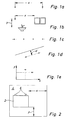
- Figure 1 illustrates a number of frequently occurring Basic requirements by a craftsman or fitter must be met. For example, it is common required two mounting positions in the most exact possible prepare relative distance to each other, for example by Drilling a borehole (Figure 1a). Furthermore, it can be required to have an object, such as a Furnishing item, like a cupboard in the case shown, and another item, as in the case shown Sink, at a certain absolute distance from another Arrange object or to a predetermined reference point are (Figure 1b).
- the mounting positions are often incorrect with the outer dimensions of the objects, since Fasteners, such as eyelets or openings, through which then fasteners such as in the assembly process Screws or the like are passed through in one Distance to the outer dimensions of the objects.
- Figure 2 illustrates another basic requirement, according to which an illustrated object 2 at a distance x to one right boundary wall and a distance y to one from one Position floor formed level on a wall 4 is.
- the subject comprises two Attachment eyelets that extend from the top of the item extend away and in the assembled state of screws be penetrated.
- the penetration point for the screws defines the one to be prepared for this requirement Mounting position for item 2, i.e. the working position for a hand-held tool device in the form of a Drill, with which two holes on the corresponding work positions must be created.
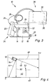
- FIG 3 shows an illustration of a manually manageable Device for the targeted positioning of a Marking means.
- the device 10 comprises a carrier 12 in Shape of a plate.
- a handle 14 for Gripping the carrier 12 provided on the carrier 12 .
- a marking means 16 in the form of a molded tongue 18 with a centering opening 20 is provided, through which a Grains can be passed through, or by means of a Pencils a visually noticeable mark on the Pad can be attached.
- a marking agent would be conceivable. In particular, it could be more complex Embodiments of markers with spray nozzles or the like may be provided.
- the distance measuring devices 22, 24 are Laser rangefinders made from overlays of the emitted and reflected waves the distance of the determine reflecting object in a known manner.
- the respective signal of the distance measuring devices 22, 24 to a computer 30 via data transmission cables 26, 28 given.
- An initially analog or digital measurement signal from Distance measuring device 22, 24 is amplified and then digitized. Or there is a digital measurement signal that given to the computer and processed there.
- a leveling device is on the carrier 12 32 in the form of a visually readable dragonfly like a Spirit level provided. This can preferably be from one electronic dragonfly, the measured value in which Positioning software-supported and therefore automated is included.
- the distance measuring devices 22, 24 and Leveling device 32 form a device 34 for Detecting the position of the wearer in relation to a reference system.
- the computer 30 together with a display 36 or one other, conveying information to a user Facility such as one speaker, one Route guidance device 38 represents.
- the computer controls and calculates the detection of the position of the wearer.
- FIG. 4 illustrates the process of measuring the one in FIG. 4 only schematically shown carrier 12 with the in In connection with Figure 3 described components to a Reference system, which is shown in FIG. 4 with reference numeral 40 is designated.
- This frame of reference 40 becomes, for example through the transition line of a wall 42 to the floor (x-axis) and through the transition line of wall 42 to a lateral one Boundary wall (y-axis) formed.
- To capture the location of the Carrier 12 becomes the carrier 12 with its base or Base plate placed against the wall 42, initially as shown in Figure 4.
- the distance measuring devices 22, 24 then show or measure the distance along the Inclined sections 44, 46.
- the carrier 12 turn until horizontal alignment is achieved (shown in dashed lines in Figure 4). In this position extends the measuring section, i.e. in the case shown Laser light path of one distance measuring device 24 along the horizontal 48 and the other along the Vertical 50.
- the data on the distance of the carrier 12 or advantageously on the marking means 16 referenced distance measuring devices 22, 24 in this horizontally aligned position give the distance of the Beam 12 from the right wall (x) and the distance from the floor (y) and thus denote the exact location, i.e. Position and Orientation of the carrier 12 with respect to the reference system 40.
- Position data can be compared.
- This position data can are either entered into the computer 30 as object data, or they can be read in as object-specific data records are or already exist as data records.
- In the present Case could be a working position that in Figure 4 with the Reference numeral 52 is designated in the form of x, y coordinates with respect to the same reference system 40. It can now a comparison of the actual position of the carrier 12 with these reaching data (x, y coordinates) of the working position 52 be compared.
- FIG. 5 illustrates the measuring principle of another device to detect the position of the carrier using the Measuring wire principle.
- the schematic shows two a base 56 at a certain known distance provided measuring rope pulleys 58, 60 and one in the form of a Dragonfly indicated leveling device 62 for the base 56.
- the measuring rope pulleys 58, 60 each comprise a down or rollable measuring rope 64, 66, which with the respective free end is attached to the carrier 12.
- About each of The rope rope pulley 58, 60 can be pulled off by Implementation of the rotary movement of the measuring rope pulleys in one electrical signal determines the measuring length and accordingly the measurement signal of the distance measuring devices 22, 24 of the Embodiment according to Figure 3 are given to a computer.
- FIG. 7 illustrates another embodiment, two rotating laser scanners 70, 72 with not necessarily horizontal arrangement to each other are provided.
- the Laser scanners 70, 72 scan the with their laser beams Drawing level.
- this laser scanner 70, 72 When using this laser scanner 70, 72 it can be used as Distance measuring devices either, as previously in the Connection with the measuring cable principle explains the distance to the carrier 12 can be determined or it can be via two angular measurements to the unique position of the carrier 12 the base, that is to the geometric connecting line 76 of the two scanners 70, 72 are determined.
- the location of the scanners 70, 72 with reference to the number 40 referred to, as discussed in Figure 6 and shown by touching or attaching the wearer to one wall or floor surface forming an axis of the reference system 40 be determined.
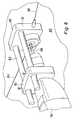
- Figure 8 shows a special and advantageous Embodiment of the device according to the invention, wherein a Power tool in the form of a drill 78 on one Carrier 12 is provided.
- the carrier 12 is via measuring cables 64, 66 based on the measuring cable principle Distance measuring devices connected (but it could also Laser distance measuring sensors are used).
- the carrier 12 comprises a plate-shaped base part 80, two of which are Extend guide rods 82 towards the drill spindle. A fastener slides on these guide rods 82 84 in the form of a clamping device, which the tool neck of the Drill 78 is stuck.
- the carrier 12 After carrying out a route guidance, the carrier 12 is on the wall 86 positioned that the drill bit of the drill 88 is exactly at the work position to be reached.
- the fastening means 84 By applying pressure to the drilling machine 78 in the drilling direction is exerted, it slides with the fastening means 84 with respect to the guide rods 82, and it is thereby exactly on a hole drilled in the working position.
- any prestressing means can be provided, such that when the pressure on the drill 78 decreases, the The drill is pulled out of the borehole again. Further drilling depth limiting means can be provided.
Landscapes
- Engineering & Computer Science (AREA)
- Physics & Mathematics (AREA)
- Mechanical Engineering (AREA)
- General Physics & Mathematics (AREA)
- Radar, Positioning & Navigation (AREA)
- Remote Sensing (AREA)
- Optics & Photonics (AREA)
- Conveying And Assembling Of Building Elements In Situ (AREA)
- Earth Drilling (AREA)
- Electrical Discharge Machining, Electrochemical Machining, And Combined Machining (AREA)
- Reduction Rolling/Reduction Stand/Operation Of Reduction Machine (AREA)
- Machine Tool Sensing Apparatuses (AREA)
Applications Claiming Priority (2)
| Application Number | Priority Date | Filing Date | Title |
|---|---|---|---|
| DE10133321 | 2001-07-09 | ||
| DE10133321A DE10133321A1 (de) | 2001-07-09 | 2001-07-09 | Einrichtung zum zielgeführten Positionieren eines handgeführten Werkzeuggeräts |
Publications (3)
| Publication Number | Publication Date |
|---|---|
| EP1275470A2 true EP1275470A2 (fr) | 2003-01-15 |
| EP1275470A3 EP1275470A3 (fr) | 2003-12-03 |
| EP1275470B1 EP1275470B1 (fr) | 2009-01-21 |
Family
ID=7691177
Family Applications (1)
| Application Number | Title | Priority Date | Filing Date |
|---|---|---|---|
| EP02014769A Expired - Lifetime EP1275470B1 (fr) | 2001-07-09 | 2002-07-04 | Dispositif pour guider une machine outil portative à un position cible |
Country Status (3)
| Country | Link |
|---|---|
| EP (1) | EP1275470B1 (fr) |
| AT (1) | ATE421407T1 (fr) |
| DE (2) | DE10133321A1 (fr) |
Cited By (8)
| Publication number | Priority date | Publication date | Assignee | Title |
|---|---|---|---|---|
| DE10237724A1 (de) * | 2002-08-17 | 2004-03-11 | Bayerische Motoren Werke Ag | Vorrichtung zur punktgenauen Zuordnung eines Werkzeugs zu einem Werkstück |
| EP1722192A2 (fr) | 2005-05-12 | 2006-11-15 | HILTI Aktiengesellschaft | Appareil manuel de mesure des coordonnées de surfaces |
| NL1037693A (nl) * | 2009-02-05 | 2010-08-09 | Holding Prodim Systems B V | Inrichting en werkwijze voor het uitzetten van contouren, punten of werken en een aanwijsinrichting voor gebruik hierbij. |
| CN103759646A (zh) * | 2014-01-27 | 2014-04-30 | 哈尔滨飞机工业集团有限责任公司 | 一种利用螺纹孔定位安装定位件的方法 |
| US9114493B2 (en) | 2011-03-23 | 2015-08-25 | Hexagon Technology Center Gmbh | Working tool positioning system |
| EP1701819B1 (fr) * | 2004-01-06 | 2018-06-20 | The Boeing Company | Perçage de trous de coordination a guidage laser |
| DE102018107726A1 (de) * | 2018-03-31 | 2019-10-02 | Natev GmbH | Werkzeug zur Bearbeitung eines Werkstücks und zur Erfassung von Bearbeitungsstellen |
| CN118204537A (zh) * | 2024-05-20 | 2024-06-18 | 常州市新创智能科技有限公司 | 一种大开度门扇打孔定位装置 |
Families Citing this family (3)
| Publication number | Priority date | Publication date | Assignee | Title |
|---|---|---|---|---|
| DE202009017424U1 (de) | 2009-12-18 | 2010-05-12 | Robert Bosch Gmbh | Markiergerät |
| DE102019218550A1 (de) * | 2019-11-29 | 2021-06-02 | Robert Bosch Gmbh | Verfahren zum Betreiben einer Handwerkzeugmaschine |
| DE102021202329A1 (de) | 2021-03-10 | 2022-09-15 | Psa Automobiles Sa | Bearbeitungsgerät und System zur Bearbeitung von Oberflächendefekten von Werkstücken |
Citations (3)
| Publication number | Priority date | Publication date | Assignee | Title |
|---|---|---|---|---|
| EP0306485B1 (fr) | 1986-05-10 | 1990-07-04 | Robert Bosch Gmbh | Machine-outil, de preference perceuse |
| DE4336730A1 (de) | 1993-10-28 | 1995-05-04 | Marquardt Gmbh | Elektrowerkzeug |
| DE19902075A1 (de) | 1999-01-20 | 2000-08-17 | Bosch Gmbh Robert | Markierwerkzeug |
Family Cites Families (8)
| Publication number | Priority date | Publication date | Assignee | Title |
|---|---|---|---|---|
| JPH0593620A (ja) * | 1991-10-02 | 1993-04-16 | Aisin Seiki Co Ltd | 位置座標測定装置 |
| DE4435573A1 (de) * | 1994-10-05 | 1996-04-11 | Zeiss Carl Jena Gmbh | Vorrichtung zur Markierung mindestens eines Arbeitsbereiches auf einer Arbeitsfläche |
| DE19709146A1 (de) * | 1997-03-06 | 1998-09-10 | Bruno Gruber | Vorrichtung zum Markieren von Bohrpunkten |
| DE29724309U1 (de) * | 1997-04-24 | 2001-01-04 | Zett-Mess-Technik GmbH, 53757 Sankt Augustin | Höhenmeß- und Anreißgerät |
| WO2000044535A1 (fr) * | 1999-01-27 | 2000-08-03 | Machine Planning Corp. | Dispositif de marquage |
| DE19909479A1 (de) * | 1999-02-09 | 2000-08-10 | Krause Johann A | Verfahren zur Positionsermittlung und/oder Steuerung ortsveränderlicher Komponenten von zum Beispiel Bearbeitungseinrichtungen und Vorrichtung zur Durchführung des Verfahrens |
| DE10013943C2 (de) * | 2000-03-21 | 2001-11-22 | Czichun Hans Heinrich | Laser-Ausrichtgerät für tragbare Handwerkzeugmaschinen, insbesondere für Handbohrmaschinen |
| DE10117953A1 (de) * | 2001-04-10 | 2002-10-24 | Hilti Ag | Positionierhilfe für Handwerkzeuggerät |
-
2001
- 2001-07-09 DE DE10133321A patent/DE10133321A1/de not_active Withdrawn
-
2002
- 2002-07-04 AT AT02014769T patent/ATE421407T1/de not_active IP Right Cessation
- 2002-07-04 DE DE50213228T patent/DE50213228D1/de not_active Expired - Lifetime
- 2002-07-04 EP EP02014769A patent/EP1275470B1/fr not_active Expired - Lifetime
Patent Citations (3)
| Publication number | Priority date | Publication date | Assignee | Title |
|---|---|---|---|---|
| EP0306485B1 (fr) | 1986-05-10 | 1990-07-04 | Robert Bosch Gmbh | Machine-outil, de preference perceuse |
| DE4336730A1 (de) | 1993-10-28 | 1995-05-04 | Marquardt Gmbh | Elektrowerkzeug |
| DE19902075A1 (de) | 1999-01-20 | 2000-08-17 | Bosch Gmbh Robert | Markierwerkzeug |
Cited By (10)
| Publication number | Priority date | Publication date | Assignee | Title |
|---|---|---|---|---|
| DE10237724A1 (de) * | 2002-08-17 | 2004-03-11 | Bayerische Motoren Werke Ag | Vorrichtung zur punktgenauen Zuordnung eines Werkzeugs zu einem Werkstück |
| EP1701819B1 (fr) * | 2004-01-06 | 2018-06-20 | The Boeing Company | Perçage de trous de coordination a guidage laser |
| EP1722192A2 (fr) | 2005-05-12 | 2006-11-15 | HILTI Aktiengesellschaft | Appareil manuel de mesure des coordonnées de surfaces |
| EP1722192A3 (fr) * | 2005-05-12 | 2012-08-01 | HILTI Aktiengesellschaft | Appareil manuel de mesure des coordonnées de surfaces |
| NL1037693A (nl) * | 2009-02-05 | 2010-08-09 | Holding Prodim Systems B V | Inrichting en werkwijze voor het uitzetten van contouren, punten of werken en een aanwijsinrichting voor gebruik hierbij. |
| US9114493B2 (en) | 2011-03-23 | 2015-08-25 | Hexagon Technology Center Gmbh | Working tool positioning system |
| CN103759646A (zh) * | 2014-01-27 | 2014-04-30 | 哈尔滨飞机工业集团有限责任公司 | 一种利用螺纹孔定位安装定位件的方法 |
| DE102018107726A1 (de) * | 2018-03-31 | 2019-10-02 | Natev GmbH | Werkzeug zur Bearbeitung eines Werkstücks und zur Erfassung von Bearbeitungsstellen |
| DE102018107726B4 (de) | 2018-03-31 | 2024-02-29 | Natev GmbH | Werkzeug zur Bearbeitung eines Werkstücks und zur Erfassung von Bearbeitungsstellen |
| CN118204537A (zh) * | 2024-05-20 | 2024-06-18 | 常州市新创智能科技有限公司 | 一种大开度门扇打孔定位装置 |
Also Published As
| Publication number | Publication date |
|---|---|
| DE10133321A1 (de) | 2003-01-30 |
| EP1275470A3 (fr) | 2003-12-03 |
| ATE421407T1 (de) | 2009-02-15 |
| EP1275470B1 (fr) | 2009-01-21 |
| DE50213228D1 (de) | 2009-03-12 |
Similar Documents
| Publication | Publication Date | Title |
|---|---|---|
| EP2254734B1 (fr) | Procédé d'usinage avec un outil électrique | |
| DE3827458C3 (de) | Verfahren und Vorrichtung zur Ermittlung der Raumkoordinaten eines beliebigen Meßpunktes | |
| EP2979062B1 (fr) | Procédé et dispositif pour l'affichage d'objets et de données d'objets d'un plan de construction | |
| EP1275470B1 (fr) | Dispositif pour guider une machine outil portative à un position cible | |
| WO2006035071A1 (fr) | Dispositif de marquage par laser | |
| DE4336730A1 (de) | Elektrowerkzeug | |
| DE102005000060A1 (de) | Handhabbares Flächenkoordinatenmessgerät | |
| EP2030048A2 (fr) | Appareil de reperage | |
| DE202004018003U1 (de) | Positioniergerät | |
| EP0403908B1 (fr) | Procédé et dispositif pour mesurer les contours d'un objet | |
| DE10239694A1 (de) | Verfahren zur Kalibrierung eines Fräsers | |
| DE102007049123A1 (de) | Markier- und/oder Nivelliervorrichtung sowie Verfahren | |
| DE102008027197B4 (de) | Verfahren zum Bearbeiten von Werkstückoberflächen | |
| DE10132142A1 (de) | Vorrichtung und Verfahren zum Ausrichten von Maschinenwellen | |
| EP1756515B1 (fr) | Appareil de marquage | |
| DE19501094A1 (de) | Verfahren und Vorrichtung zur Kalibrierung von Bewegungseinrichtungen | |
| DE19609511C2 (de) | Hilfsvorrichtung für handgeführte Werkzeuge | |
| DE19629616C2 (de) | Vorrichtung und Verfahren zum manuellen Einstellen, Messen, ggf. Prüfen von Werkzeugen für Bearbeitungsmaschinen | |
| DE102012219345A1 (de) | Vorrichtung und Verfahren zur optischen und/oder akustischen Anzeige einer Ausrichtung einer Handwerkzeugmaschine gegenüber einem Werkstück | |
| DE102017003641A1 (de) | Verfahren zur Messung von Koordinaten oder Eigenschaften einer Werkstückoberfläche | |
| DE202007008253U1 (de) | Anreiß- und Messgerät mit Ankörnvorrichtung | |
| DE102010026102B4 (de) | Verfahren zur Aufzeichnung von Aufbaumarkierungen für eine Fertigungsanlage, insbesondere im Fahrzeugbau | |
| DE10154978A1 (de) | Anreißmessschieber | |
| DE10116015A1 (de) | Verfahren und Vorrichtung zum Positionieren eines Handgeräts auf einer Baustelle | |
| DE102010026891A1 (de) | Vorrichtung zur Vermessung von Objekten |
Legal Events
| Date | Code | Title | Description |
|---|---|---|---|
| PUAI | Public reference made under article 153(3) epc to a published international application that has entered the european phase |
Free format text: ORIGINAL CODE: 0009012 |
|
| AK | Designated contracting states |
Kind code of ref document: A2 Designated state(s): AT BE BG CH CY CZ DE DK EE ES FI FR GB GR IE IT LI LU MC NL PT SE SK TR |
|
| AX | Request for extension of the european patent |
Free format text: AL;LT;LV;MK;RO;SI |
|
| PUAL | Search report despatched |
Free format text: ORIGINAL CODE: 0009013 |
|
| AK | Designated contracting states |
Kind code of ref document: A3 Designated state(s): AT BE BG CH CY CZ DE DK EE ES FI FR GB GR IE IT LI LU MC NL PT SE SK TR |
|
| AX | Request for extension of the european patent |
Extension state: AL LT LV MK RO SI |
|
| RIC1 | Information provided on ipc code assigned before grant |
Ipc: 7B 23Q 16/00 B Ipc: 7B 23Q 15/22 A Ipc: 7B 23Q 17/22 B Ipc: 7B 23Q 17/24 B Ipc: 7B 25H 7/04 B |
|
| 17P | Request for examination filed |
Effective date: 20031223 |
|
| AKX | Designation fees paid |
Designated state(s): AT BE BG CH CY CZ DE DK EE ES FI FR GB GR IE IT LI LU MC NL PT SE SK TR |
|
| 17Q | First examination report despatched |
Effective date: 20071221 |
|
| GRAP | Despatch of communication of intention to grant a patent |
Free format text: ORIGINAL CODE: EPIDOSNIGR1 |
|
| GRAS | Grant fee paid |
Free format text: ORIGINAL CODE: EPIDOSNIGR3 |
|
| GRAA | (expected) grant |
Free format text: ORIGINAL CODE: 0009210 |
|
| AK | Designated contracting states |
Kind code of ref document: B1 Designated state(s): AT BE BG CH CY CZ DE DK EE ES FI FR GB GR IE IT LI LU MC NL PT SE SK TR |
|
| REG | Reference to a national code |
Ref country code: GB Ref legal event code: FG4D Free format text: NOT ENGLISH |
|
| REG | Reference to a national code |
Ref country code: CH Ref legal event code: EP Ref country code: CH Ref legal event code: NV Representative=s name: TROESCH SCHEIDEGGER WERNER AG |
|
| REG | Reference to a national code |
Ref country code: IE Ref legal event code: FG4D Free format text: LANGUAGE OF EP DOCUMENT: GERMAN |
|
| REF | Corresponds to: |
Ref document number: 50213228 Country of ref document: DE Date of ref document: 20090312 Kind code of ref document: P |
|
| PG25 | Lapsed in a contracting state [announced via postgrant information from national office to epo] |
Ref country code: FI Free format text: LAPSE BECAUSE OF FAILURE TO SUBMIT A TRANSLATION OF THE DESCRIPTION OR TO PAY THE FEE WITHIN THE PRESCRIBED TIME-LIMIT Effective date: 20090121 Ref country code: ES Free format text: LAPSE BECAUSE OF FAILURE TO SUBMIT A TRANSLATION OF THE DESCRIPTION OR TO PAY THE FEE WITHIN THE PRESCRIBED TIME-LIMIT Effective date: 20090502 |
|
| REG | Reference to a national code |
Ref country code: IE Ref legal event code: FD4D |
|
| PG25 | Lapsed in a contracting state [announced via postgrant information from national office to epo] |
Ref country code: PT Free format text: LAPSE BECAUSE OF FAILURE TO SUBMIT A TRANSLATION OF THE DESCRIPTION OR TO PAY THE FEE WITHIN THE PRESCRIBED TIME-LIMIT Effective date: 20090622 Ref country code: SE Free format text: LAPSE BECAUSE OF FAILURE TO SUBMIT A TRANSLATION OF THE DESCRIPTION OR TO PAY THE FEE WITHIN THE PRESCRIBED TIME-LIMIT Effective date: 20090421 |
|
| PG25 | Lapsed in a contracting state [announced via postgrant information from national office to epo] |
Ref country code: DK Free format text: LAPSE BECAUSE OF FAILURE TO SUBMIT A TRANSLATION OF THE DESCRIPTION OR TO PAY THE FEE WITHIN THE PRESCRIBED TIME-LIMIT Effective date: 20090121 Ref country code: CZ Free format text: LAPSE BECAUSE OF FAILURE TO SUBMIT A TRANSLATION OF THE DESCRIPTION OR TO PAY THE FEE WITHIN THE PRESCRIBED TIME-LIMIT Effective date: 20090121 Ref country code: IE Free format text: LAPSE BECAUSE OF FAILURE TO SUBMIT A TRANSLATION OF THE DESCRIPTION OR TO PAY THE FEE WITHIN THE PRESCRIBED TIME-LIMIT Effective date: 20090121 Ref country code: EE Free format text: LAPSE BECAUSE OF FAILURE TO SUBMIT A TRANSLATION OF THE DESCRIPTION OR TO PAY THE FEE WITHIN THE PRESCRIBED TIME-LIMIT Effective date: 20090121 |
|
| PLBE | No opposition filed within time limit |
Free format text: ORIGINAL CODE: 0009261 |
|
| STAA | Information on the status of an ep patent application or granted ep patent |
Free format text: STATUS: NO OPPOSITION FILED WITHIN TIME LIMIT |
|
| PG25 | Lapsed in a contracting state [announced via postgrant information from national office to epo] |
Ref country code: SK Free format text: LAPSE BECAUSE OF FAILURE TO SUBMIT A TRANSLATION OF THE DESCRIPTION OR TO PAY THE FEE WITHIN THE PRESCRIBED TIME-LIMIT Effective date: 20090121 |
|
| PGFP | Annual fee paid to national office [announced via postgrant information from national office to epo] |
Ref country code: AT Payment date: 20090723 Year of fee payment: 8 Ref country code: CH Payment date: 20090727 Year of fee payment: 8 Ref country code: NL Payment date: 20090724 Year of fee payment: 8 |
|
| 26N | No opposition filed |
Effective date: 20091022 |
|
| PG25 | Lapsed in a contracting state [announced via postgrant information from national office to epo] |
Ref country code: BG Free format text: LAPSE BECAUSE OF FAILURE TO SUBMIT A TRANSLATION OF THE DESCRIPTION OR TO PAY THE FEE WITHIN THE PRESCRIBED TIME-LIMIT Effective date: 20090421 |
|
| BERE | Be: lapsed |
Owner name: METABOWERKE G.M.B.H. Effective date: 20090731 |
|
| PG25 | Lapsed in a contracting state [announced via postgrant information from national office to epo] |
Ref country code: MC Free format text: LAPSE BECAUSE OF NON-PAYMENT OF DUE FEES Effective date: 20090731 |
|
| PGFP | Annual fee paid to national office [announced via postgrant information from national office to epo] |
Ref country code: IT Payment date: 20090730 Year of fee payment: 8 |
|
| PG25 | Lapsed in a contracting state [announced via postgrant information from national office to epo] |
Ref country code: BE Free format text: LAPSE BECAUSE OF NON-PAYMENT OF DUE FEES Effective date: 20090731 |
|
| PG25 | Lapsed in a contracting state [announced via postgrant information from national office to epo] |
Ref country code: GR Free format text: LAPSE BECAUSE OF FAILURE TO SUBMIT A TRANSLATION OF THE DESCRIPTION OR TO PAY THE FEE WITHIN THE PRESCRIBED TIME-LIMIT Effective date: 20090422 |
|
| REG | Reference to a national code |
Ref country code: NL Ref legal event code: V1 Effective date: 20110201 |
|
| REG | Reference to a national code |
Ref country code: CH Ref legal event code: PL |
|
| PG25 | Lapsed in a contracting state [announced via postgrant information from national office to epo] |
Ref country code: LI Free format text: LAPSE BECAUSE OF NON-PAYMENT OF DUE FEES Effective date: 20100731 Ref country code: LU Free format text: LAPSE BECAUSE OF NON-PAYMENT OF DUE FEES Effective date: 20090704 Ref country code: CH Free format text: LAPSE BECAUSE OF NON-PAYMENT OF DUE FEES Effective date: 20100731 |
|
| PG25 | Lapsed in a contracting state [announced via postgrant information from national office to epo] |
Ref country code: AT Free format text: LAPSE BECAUSE OF NON-PAYMENT OF DUE FEES Effective date: 20100704 Ref country code: IT Free format text: LAPSE BECAUSE OF NON-PAYMENT OF DUE FEES Effective date: 20100704 Ref country code: NL Free format text: LAPSE BECAUSE OF NON-PAYMENT OF DUE FEES Effective date: 20110201 |
|
| PG25 | Lapsed in a contracting state [announced via postgrant information from national office to epo] |
Ref country code: TR Free format text: LAPSE BECAUSE OF FAILURE TO SUBMIT A TRANSLATION OF THE DESCRIPTION OR TO PAY THE FEE WITHIN THE PRESCRIBED TIME-LIMIT Effective date: 20090121 |
|
| PG25 | Lapsed in a contracting state [announced via postgrant information from national office to epo] |
Ref country code: CY Free format text: LAPSE BECAUSE OF FAILURE TO SUBMIT A TRANSLATION OF THE DESCRIPTION OR TO PAY THE FEE WITHIN THE PRESCRIBED TIME-LIMIT Effective date: 20090121 |
|
| REG | Reference to a national code |
Ref country code: DE Ref legal event code: R082 Ref document number: 50213228 Country of ref document: DE Representative=s name: LORENZ & KOLLEGEN PATENTANWAELTE PARTNERSCHAFT, DE |
|
| REG | Reference to a national code |
Ref country code: FR Ref legal event code: PLFP Year of fee payment: 15 |
|
| PGFP | Annual fee paid to national office [announced via postgrant information from national office to epo] |
Ref country code: GB Payment date: 20160722 Year of fee payment: 15 Ref country code: DE Payment date: 20160721 Year of fee payment: 15 |
|
| PGFP | Annual fee paid to national office [announced via postgrant information from national office to epo] |
Ref country code: FR Payment date: 20160722 Year of fee payment: 15 |
|
| REG | Reference to a national code |
Ref country code: DE Ref legal event code: R119 Ref document number: 50213228 Country of ref document: DE |
|
| GBPC | Gb: european patent ceased through non-payment of renewal fee |
Effective date: 20170704 |
|
| REG | Reference to a national code |
Ref country code: FR Ref legal event code: ST Effective date: 20180330 |
|
| PG25 | Lapsed in a contracting state [announced via postgrant information from national office to epo] |
Ref country code: GB Free format text: LAPSE BECAUSE OF NON-PAYMENT OF DUE FEES Effective date: 20170704 Ref country code: DE Free format text: LAPSE BECAUSE OF NON-PAYMENT OF DUE FEES Effective date: 20180201 |
|
| PG25 | Lapsed in a contracting state [announced via postgrant information from national office to epo] |
Ref country code: FR Free format text: LAPSE BECAUSE OF NON-PAYMENT OF DUE FEES Effective date: 20170731 |