EP1275947B1 - Verfahren zur Verringerung von Gesamttemperaturfehlern und dessen Umsetzung in einer multifunktionalen Sonde - Google Patents
Verfahren zur Verringerung von Gesamttemperaturfehlern und dessen Umsetzung in einer multifunktionalen Sonde Download PDFInfo
- Publication number
- EP1275947B1 EP1275947B1 EP02254905A EP02254905A EP1275947B1 EP 1275947 B1 EP1275947 B1 EP 1275947B1 EP 02254905 A EP02254905 A EP 02254905A EP 02254905 A EP02254905 A EP 02254905A EP 1275947 B1 EP1275947 B1 EP 1275947B1
- Authority
- EP
- European Patent Office
- Prior art keywords
- air temperature
- total air
- probe
- attack
- function
- Prior art date
- Legal status (The legal status is an assumption and is not a legal conclusion. Google has not performed a legal analysis and makes no representation as to the accuracy of the status listed.)
- Expired - Lifetime
Links
- 239000000523 sample Substances 0.000 title claims description 160
- 238000000034 method Methods 0.000 title claims description 27
- 238000011084 recovery Methods 0.000 claims description 57
- 238000012545 processing Methods 0.000 claims description 16
- 230000006870 function Effects 0.000 description 26
- 238000012937 correction Methods 0.000 description 14
- 238000010586 diagram Methods 0.000 description 6
- 238000013461 design Methods 0.000 description 4
- 238000013459 approach Methods 0.000 description 2
- 238000004364 calculation method Methods 0.000 description 2
- 238000004891 communication Methods 0.000 description 2
- 230000000875 corresponding effect Effects 0.000 description 2
- 230000000694 effects Effects 0.000 description 2
- 230000035945 sensitivity Effects 0.000 description 2
- 230000003068 static effect Effects 0.000 description 2
- 238000013528 artificial neural network Methods 0.000 description 1
- 238000006243 chemical reaction Methods 0.000 description 1
- 230000008867 communication pathway Effects 0.000 description 1
- 230000002596 correlated effect Effects 0.000 description 1
- 238000005314 correlation function Methods 0.000 description 1
- 230000007423 decrease Effects 0.000 description 1
- 230000001419 dependent effect Effects 0.000 description 1
- 239000012530 fluid Substances 0.000 description 1
- 238000011835 investigation Methods 0.000 description 1
- 230000013011 mating Effects 0.000 description 1
- 238000005259 measurement Methods 0.000 description 1
- 238000005070 sampling Methods 0.000 description 1
- 238000012360 testing method Methods 0.000 description 1
Images




Classifications
-
- G—PHYSICS
- G01—MEASURING; TESTING
- G01K—MEASURING TEMPERATURE; MEASURING QUANTITY OF HEAT; THERMALLY-SENSITIVE ELEMENTS NOT OTHERWISE PROVIDED FOR
- G01K13/00—Thermometers specially adapted for specific purposes
- G01K13/02—Thermometers specially adapted for specific purposes for measuring temperature of moving fluids or granular materials capable of flow
- G01K13/028—Thermometers specially adapted for specific purposes for measuring temperature of moving fluids or granular materials capable of flow for use in total air temperature [TAT] probes
-
- B—PERFORMING OPERATIONS; TRANSPORTING
- B64—AIRCRAFT; AVIATION; COSMONAUTICS
- B64D—EQUIPMENT FOR FITTING IN OR TO AIRCRAFT; FLIGHT SUITS; PARACHUTES; ARRANGEMENT OR MOUNTING OF POWER PLANTS OR PROPULSION TRANSMISSIONS IN AIRCRAFT
- B64D43/00—Arrangements or adaptations of instruments
- B64D43/02—Arrangements or adaptations of instruments for indicating aircraft speed or stalling conditions
-
- G—PHYSICS
- G01—MEASURING; TESTING
- G01K—MEASURING TEMPERATURE; MEASURING QUANTITY OF HEAT; THERMALLY-SENSITIVE ELEMENTS NOT OTHERWISE PROVIDED FOR
- G01K13/00—Thermometers specially adapted for specific purposes
- G01K13/02—Thermometers specially adapted for specific purposes for measuring temperature of moving fluids or granular materials capable of flow
-
- G—PHYSICS
- G01—MEASURING; TESTING
- G01P—MEASURING LINEAR OR ANGULAR SPEED, ACCELERATION, DECELERATION, OR SHOCK; INDICATING PRESENCE, ABSENCE, OR DIRECTION, OF MOVEMENT
- G01P13/00—Indicating or recording presence, absence, or direction, of movement
- G01P13/02—Indicating direction only, e.g. by weather vane
- G01P13/025—Indicating direction only, e.g. by weather vane indicating air data, i.e. flight variables of an aircraft, e.g. angle of attack, side slip, shear, yaw
Definitions
- the present invention relates to multi-function air data sensing probes (multi-function probes or MFPs) and to total air temperature (TAT) sensors or probes. More particularly, the present invention relates to correction of TAT recovery errors.
- OAT outside air temperature
- TAT total air temperature
- T t total air temperature
- MFP multi-function probe
- de-icing heater error DHE
- the recovery temperature T r is the adiabatic value of local air temperature on each portion of the aircraft surface due to incomplete recovery of the kinetic energy.
- Static air temperature (SAT or T s ) is the temperature of the undisturbed air through which the aircraft is about to fly.
- the recovery factor is the proportion of kinetic energy converted to heat. A recovery factor of unity means all kinetic energy is converted to heat. In such cases, the recovery temperature T r is equal to the total temperature.
- the recovery error is the per unit or fractional total temperature error.
- both recovery error and DHE can be large enough to move outside of acceptable limits.
- the local flow angles are a function or probe placement on the aircraft and flight envelope conditions. Recovery error and DHE are particularly large at low speeds. This also happens to be where the aircraft has the most extreme values of angle of attack (AOA) and angle of sideslip (AOS). The extreme aircraft angles are what cause the extreme local AOAs.
- AOA angle of attack
- AOS angle of sideslip
- Multi-function probes or MFPs are used in air data systems to provide, among other things, accurate compensation of sideslip of an air vehicle. These MFPs are independent probes that are not pneumatically coupled, but which have processors for interchanging electrical signals between the probes.
- MFP is the SmartProbeTM sold by the Goodrich Corporation.
- Multi-function probes include processing circuitry located at the probe itself as part of its instrument package. MFPs can be used, for example, to calculate an MFP local AOA, an aircraft AOA, and an aircraft AOS in addition to airspeed, altitude and Mach number.
- the present invention provides a method and apparatus of generating for an aircraft a total air temperature compensated for recovery or deicing heater error as set out in claims 1 and 11.
- Embodiments provide a method of generating for an aircraft a total air temperature compensated for recovery or deicing heater error, the method comprising measuring a total air temperature with a total air temperature probe; determining a local angle of attack for the total air temperature probe; and generating a corrected total air temperature, compensated for recovery or deicing heater error, as a function of the measured total air temperature and the determined local angle of attack for the total air temperature probe.
- Embodiments also provide a multi-function probe for air data sensing comprising a barrel having a plurality of pressure sensing ports for sensing a plurality of pressures; instrumentation coupled to the plurality of pressure sensing ports for providing electrical signals indicative of the plurality of pressures; an input receiving a measured total air temperature from a total air temperature probe; and processing circuitry coupled to the instrumentation and the input and configured to determine a local angle of attack for the total air temperature probe as a function of the electrical signals indicative of the plurality of pressures, the processing circuitry further being configured to generate a corrected total air temperature, which is compensated for recovery and deicing heater error, as a function of the measured total air temperature and the determined local angle of attack for the total air temperature probe.
- a method of generating, for an aircraft, a total air temperature compensated for recovery or deicing heater error includes measuring a total air temperature with a total air temperature probe. A local angle of attack for the total air temperature probe is determined. Then, a corrected total air temperature, compensated for recovery or deicing heater error, is generated as a function of the measured total air temperature and the determined local angle of attack for the total air temperature probe.
- FIG. 1 is a schematic representation of a nose portion of an aircraft (indicated generally at 10).
- airplane 10 includes a mounted MFP 14 and a TAT probe 16.
- TAT probe 16 can be a probe such as shown in U.S. Patent No. 5,653,538 , to Phillips, entitled “TOTAL TEMPERATURE PROBE", or such as shown in U.S. Patent 5,731,507, to Hagen et al. , entitled "INTEGRAL AIRFOIL TOTAL TEMPEARTURE SENSOR”.
- TAT probe 16 can also be of other designs.
- TAT probe 16 measures the total temperature of an airflow (shown diagrammatically at 17) as the airflow is brought to rest, without removal or addition of heat. TAT probe 16 provides an output 18 which is indicative of the measured TAT. Output 18, which is provided to MFP 14 (and optionally to a separate air data computer 38) can be a resistance value indicative of the TAT measured by probe 16.
- MFP 14 and optionally to a separate air data computer 38
- DHE de-icing heater error
- the recovery error and DHE are particularly large at low aircraft airspeeds.
- Multi-function probe 14 can be one of multiple MFPs mounted on the nose portion of aircraft 10.
- a multi-function probe or MFP is defined as an air data sensing probe in which a computer is integrally attached as a processor to the probe, and the sensing portions of the probe itself protrude in the airstream that moves past the aircraft skin.
- the processor is an integrated housing immediately inside the skin.
- the outputs from MFPs are digital electrical signals representing pressures derived from sampling multiple pressure readings from internal pressure sensors.
- the internal pressure sensors of an MFP can be either differential sensors or absolute sensors that receive the pressure signals and convert them into electrical signals that are then digitized.
- the TAT correction or compensation methods disclosed herein are implemented within an air data computer (ADC) embodied in the processing circuitry integral to the MFP housing, or within multiple ADCs located within multiple MFPs. In yet other embodiments, the methods are implemented within an optional ADC 38 which is coupled to, but located remote from, the MFP 14.
- ADC air data computer
- Multi-function probe 14 may be a probe such as that shown in the United States Patent 4,378,696 , or other similar patents. As shown schematically in FIG. 1 , the probe has barrel 14 with a suitable port for sensing pitot pressure at a leading end of the probe indicated at 14B. Angle of attack sensing ports are placed on the top and bottom of the probe, and the top port is illustrated schematically at 14C. A mating port is on the lower portion, as is well known, for measuring the angle of attack by sensing the differentials in pressure between the upper port and the lower port. The lower port on probe 14 senses a pressure designated P ⁇ 1 , and the upper port shown at 14C senses a pressure designated P ⁇ 2 .
- the electronics within instrument housings 14D is electrically coupled to TAT probe 16 via electrical connection 24.
- Electrical connection 24 can be a data bus, electrical cables, or other types of communication pathways for communicating information.
- the optional remote ADC 38 within which the methods of the present invention can be implemented.
- the TAT error reducing techniques of the present invention are implemented within an ADC contained within the housings 14D associated with MFP 14.
- optional ADC 38 can be omitted if desired.
- FIG. 2 is a schematic illustration of a portion of a air data sensing probe 19 which can be used in some embodiments of the present invention.
- Probe 19 includes the TAT probe 16 formed integrally with the MFP 14. With the exception of the functions of probes 14 and 16 being integrated into a single probe 19, probes 14 and 16 of integral air data sensing probe 19 function substantially the same as described with reference to FIG. 1 , and as described further below.
- Probe 19 shown in FIG. 3 also includes an instrument housing, similar to instrument housing 14D shown in FIG. 1 .
- Multi-function probe circuitry 23 is shown schematically coupled to probe 14.
- Circuitry 23 is positioned within the corresponding housing 14D and in the illustrated embodiment comprises an air data computer (ADC).
- ADC air data computer
- Inputs are illustrated schematically as the ⁇ 1 pressure port 14E ⁇ 2 pressure port 14C and the total pressure port 14B.
- the ⁇ 2 pressure port and total pressure port correspond to those shown in FIG. 2 for probe 14.
- the ⁇ 1 pressure port corresponds to the lower port (not shown in FIG. 1 ) on the probe.
- Processing and communications circuitry 37 includes a microcontroller 36 and related memory and communications circuits all forming part of the ADC (i.e., circuitry 23).
- the ADC can also include other circuits and devices such as electromagnetic filters for reducing EMI interference, heater control circuits, and power supplies.
- Air data computer or circuitry 23 also includes and/or is coupled to data bus 24 for receiving information from, or transmitting information to, other devices such as TAT probe 16 and other MFPs in the system.
- the methods of the present invention can be implemented within the air data computers of one or more MFPs, or can be implemented in a separate and remotely positioned air data computer.
- the present invention is based, in part, upon the recognition that if information from a nearby MFP can be used to estimate the local AOA at probe 16, then the error can be reduced. It has been found that, for at least some TAT probe implementations, the recovery error is within acceptable limits at all speeds and all parts of the flight envelope when the heater of the TAT probe is turned off. However, in at least some configurations of TAT probe 16, if the heater is turned on, the errors are too large when local AOA is beyond 10°.
- using a quadratic curve fit to account for the TAT probe recovery error associated with local (to the TAT probe) AOA would reduce the TAT recovery error and the DHE to acceptable levels. This allows the extension of the range of local AOA where the TAT probe 16 functions within specification.
- the invention utilizes the ability of MFP 14 to calculate parameters such as local AOA, TAT heater state, and even aircraft parameters such as AOA and AOS that might influence the relationship between local AOA at the MFP 14 and local AOA at the TAT probe 16.
- the trends in the data taken were such that over the range of 75 to 150 KIAS (knot indicated airspeed) local airspeed, the recovery error was less than 0.5°C up to local AOAs of 25 degrees if the heater was off when the nominal total temperature was assumed to be 25°C. As the speed increases, the error increases slightly, but the expected aircraft flight envelope should be limited in AOS at the higher speeds (and higher altitude) to the point that a heater off condition is of little concern. When the heater power is "ON" in the TAT probe however, the error was greater than 0.5°C when the local AOA was over 10°.
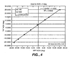
- FIG. 4 is a plot illustrating the relationship, for one particular implementation, of the local AOA at the TAT probe 16 and the local AOA at the MFP 14, when the aircraft AOS is zero.
- FIG. 4 when the aircraft AOS is zero there is a direct, linear, correlation between the MFP local AOA and the local AOA at the TAT probe.
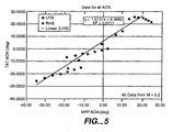
- the data shown in FIG. 4 was taken for Mach (M) of 0.2. However, when aircraft AOS is considered, the correlation is not as direct.
- FIG. 5 shows data for a range of aircraft AOS that correlate the local AOA at the TAT probe and the local AOA at the MFP.
- the changes in local AOA at the TAT probe is more sensitive to AOS than it is at higher aircraft AOA in this particular example.
- the sensitivity to AOS is less and at the highest aircraft AOA, the sensitivity is the least.
- the local AOA at the TAT probe is what is predicted by the equation shown in FIG. 4 .
- the local AOA at the TAT probe can then be correlated to the actual TAT probe local AOA for purposes of comparison.
- the local AOA at the MFP would be -35.1° or -12.0° (depending on which side the wind is coming from).
- the predicted local AOA at the TAT probe would be -32.8° or -8.5°.
- the actual value of the local AOA at the TAT probe would be -25.3° or -14.5°.
- the local AOA at the MFP is determined for an aircraft condition.
- the local AOA at the TAT probe can be predicted using a relationship such as shown in the equation in FIG. 4 .
- the "error" is now how much the AOS has influenced the local AOA at the TAT probe.
- the local AOA at the TAT probe can then be compensated for AOS.
- FIG. 6 the recovery error is shown for one example implementation in the heater power "ON" condition as a function of local AOA at approximately Mach 0.2.
- FIG. 7 illustrates the relationship between local AOA and aircraft AOA in one example.
- the correction predicted would be about 2.45% and at a local AOA of -25.3°, the correction prediction would be 1.53% based on a modified quadratic curve fit for the experimental data (in this case a positive local AOA has the same impact on recovery error as does a negative local AOA). Thus, in neglecting sideslip, the error would be about 0.92%. In air at 25°C, this translates to about 2.75°C of error. On the other side, a correction at an assumed -8.5° local AOA would be zero, but the actual local AOA of -14.5 would introduce an error of approximately 0.45% or 1.35°C in standard air.
- Methods can be used to determine aircraft AOS, for example using separate symmetrically mounted MFPs.
- method of calculating aircraft AOS are well known in the art.
- the aircraft AOS calculations can be implemented within MFP 14, or implemented remotely and provided to MFP 14. The invention is not limited by choice of AOS calculation method.
- the determination of local AOA at the TAT probe 16 can be done using a two-dimensional look-up table with the inputs being local AOA at the MFP 14 and aircraft AOS. Once the local AOA at TAT probe 16 is known, curves such as those shown in FIGS. 8 and 9 can be used to determine the appropriate recovery error correction.
- FIGS. 8 and 9 illustrate quadratic curves which correlate the recovery error for a TAT probe to the TAT probe's local AOA with the heater in the "ON" and “OFF” conditions, respectively.
- a different curve error-AOA relationship
- Functions for each of the recovery error curves in FIGS. 8 and 9 are also provided.
- the curves shown in FIGS. 8 and 9 are examples for one particular TAT probe design and configuration, and do not limit the invention to these particular curves or functions.
- an additional correlation between the aircraft flight conditions based on information in the Air Data system and the local airspeed at the TAT probe must be made. Note that the uncorrected error decreases as local speed increases.
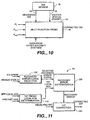
- FIG. 10 is a block diagram illustrating a system for providing a TAT with reduced recovery errors in accordance with the invention.
- TAT probe or sensor 16 provides at output(s) 18 an indication of the TAT measured by that probe.
- TAT probe 16 provides at output 18 an indication of the status (ON/OFF) of the TAT probe heater. If TAT probe 16 does not provide the heater status, MFP 14 can obtain this information from other sources.
- MFP 14 receives as inputs the pressures P t , P ⁇ 1 and P ⁇ 2 described above. Using these inputs, a local AOA at the MFP can be calculated as is known in the art. Using these inputs and data from other aircraft systems (for example other MFPs), an aircraft AOS can be calculated within MFP 14. The aircraft AOS can also be determined elsewhere and provided to MFP 14. Using a look-up table or other methods such as derived correlation functions, the local AOA at MFP 14 and the aircraft AOS can be used to estimate a local AOA at TAT probe 16.
- an appropriate recovery error curve can be selected for use in correcting the TAT. Selection of the appropriate recovery error function or curve is dependent upon the heater status and the local airspeed (knots indicated airspeed) as is shown in FIGS. 8 and 9 , for example. Once the appropriate recovery error curve is selected, the processing circuitry within MFP 14 provides a corrected TAT estimation as an output.
- FIG. 11 is a block diagram illustrating the recovery error correction function implemented by MFP 14 in greater detail.
- the processing circuitry in MFP 14 can be considered to implement a recovery error curve selection function 100, a TAT probe local AOA determination function 110, a recovery error determination function 120 and a TAT correction function 130.
- recovery error curve selection function 100 receives as inputs the indicated airspeed of the aircraft and the heater status. The indicated airspeed input can be calculated within MFP 14, or can be provided in the data from other aircraft systems if desired. Selection of the appropriate recovery error curve can be generally as described above.
- recovery error curve selector 100 selects one of first and second sets of recovery error curves corresponding to the heater status (i.e., sets of curves such as those shown in FIG. 8 or in FIG. 9 ). Then, using the indicated airspeed input, recovery error curve selector 100 selects the appropriate one of the set of curves for the particular airspeed of the aircraft interpolating if necessary.
- the TAT probe local AOA determination function 110 can estimate the local AOA at TAT probe 16 generally as described above.
- the MFP local AOA calculated within MFP 14 and the aircraft AOS can be used as inputs to a two-dimensional look-up table to select the appropriate TAT probe local AOA.
- the values within the look-up table can be established using Computational Fluid Dynamics (CFD) testing, modeling, or by other methods.
- functions describing the relationship between the TAT probe local AOA and combinations of MFP local AOA and aircraft AOS can be identified and used in TAT probe local AOA determiner 110.
- recovery error determination function 120 identifies the recovery error for the particular TAT probe local AOA.
- recovery error is negligible for local AOAs below a threshold (in the illustrated embodiment, 10°).
- the recovery error can be ignored or set to a predetermined small value.
- the measured TAT can be corrected using the determined recovery error to provide a corrected TAT.
- the range of operating conditions specifically the local AOA of the TAT probe in which the TAT is considered to be reliable can be greatly extended as compared to conventional systems.
Landscapes
- Physics & Mathematics (AREA)
- General Physics & Mathematics (AREA)
- Engineering & Computer Science (AREA)
- Aviation & Aerospace Engineering (AREA)
- Measuring Fluid Pressure (AREA)
- Indication And Recording Devices For Special Purposes And Tariff Metering Devices (AREA)
- Arrangements For Transmission Of Measured Signals (AREA)
Claims (17)
- Verfahren zur Erzeugung einer Gesamtlufttemperatur für ein Luftfahrzeug (10), wobei die Gesamtlufttemperatur um einen wiederherstellungs- oder Entfrosterheizungs-Fehler kompensiert ist, wobei das Verfahren die folgenden Schritte aufweist:Messen einer Gesamtlufttemperatur mit einem Gesamtluft-Temperaturmessfühler (16), gekennzeichnet durch:Bestimmen eines lokalen Anstellwinkels für den Gesamtluft-Temperaturmessfühler (16); undErzeugen einer korrigierten Gesamtlufttemperatur, welche um einen Wiederherstellungs- oder Entfrosterheizungs-Fehler kompensiert ist, als Funktion der gemessenen Gesamtlufttemperatur und des bestimmten lokalen Anstellwinkels für den Gesamtluft-Temperaturmessfühler (16).
- Verfahren nach Anspruch 1, welches des Weiteren Folgendes aufweist:Bestimmen einer Luftgeschwindigkeit; unddadurch gekennzeichnet, dass der Schritt der Erzeugung der korrigierten Gesamtlufttemperatur des Weiteren den Schritt der Erzeugung der korrigierten Gesamtlufttemperatur als Funktion der gemessenen Gesamtlufttemperatur, der Luftgeschwindigkeit, sowie des bestimmten lokalen Anstellwinkels für den Gesamtluft-Temperaturmessfühler aufweist.
- Verfahren nach Anspruch 2, welches des Weiteren Folgendes aufweist:Bestimmen eines EIN/AUS-Zustands einer Heizung des Gesamtluft-Temperaturmessfühlers (16); undwobei der Schritt der Erzeugung der korrigierten Gesamtlufttemperatur des Weiteren den Schritt der Erzeugung der korrigierten Gesamtlufttemperatur als Funktion der gemessenen Gesamtlufttemperatur, des bestimmten lokalen Anstellwinkels für den Gesamtluft-Temperaturmessfühler (16), der Luftgeschwindigkeit sowie des EIN/AUS-Zustands der Heizung aufweist.
- Verfahren nach Anspruch 3, dadurch gekennzeichnet, dass der Schritt der Bestimmung des lokalen Anstellwinkels für den Gesamtluft-Temperaturmessfühler (16) des Weiteren die Verwendung einer Verarbeitungs-Schaltkreisanordnung (23) eines Multifunktions-Messfühlers (14 oder 19) zur Berechnung eines lokalen Anstellwinkels für den Multifunktions-Messfühler (14 oder 19) und zur Bestimmung des lokalen Anstellwinkels für den Gesamtluft-Temperaturmessfühler (16) als Funktion des lokalen Anstellwinkels für den Multifunktions-Messfühler (14 oder 19) aufweist.
- Verfahren nach Anspruch 4, dadurch gekennzeichnet, dass der Schritt der Bestimmung des lokalen Anstellwinkels für den Gesamtluft-Temperaturmessfühler (16) des Weiteren den Schritt der Bestimmung des lokalen Anstellwinkels für den Gesamtluft-Temperaturmessfühler (16) darüber hinaus als Funktion eines Schiebewinkels eines Luftfahrzeugs aufweist.
- Verfahren nach Anspruch 5, dadurch gekennzeichnet, dass der Schritt der Erzeugung der korrigierten Gesamtlufttemperatur des Weiteren den Schritt der Erzeugung der korrigierten Gesamtlufttemperatur unter Verwendung der Verarbeitungs-Schaltkreisanordnung (23) des Multifunktions-Messfühlers aufweist.
- Verfahren nach Anspruch 6, dadurch gekennzeichnet, dass der Schritt der Erzeugung der korrigierten Gesamtlufttemperatur des Weiteren die folgenden Schritte aufweist:Auswählen einer Beziehung zwischen Fehler und Anstellwinkel basierend auf der Luftgeschwindigkeit;Bestimmen eines Fehlers als Funktion des lokalen Anstellwinkels für den Gesamtluft-Temperaturmessfühler (16) unter Verwendung der ausgewählten Fehler-Anstellwinkel-Beziehung; undErzeugen der korrigierten Gesamtlufttemperatur aus der gemessenen Gesamtlufttemperatur und dem Fehler.
- Verfahren nach Anspruch 7, dadurch gekennzeichnet, dass der Schritt des Auswählens der Fehler-Anstellwinkel-Beziehung den Schritt des Auswählens einer Fehlergleichung basierend auf der Luftgeschwindigkeit aufweist.
- Verfahren nach Anspruch 8, dadurch gekennzeichnet, dass die Luftgeschwindigkeit eine lokale Luftgeschwindigkeit des Gesamtluft-Temperaturmessfühlers (16) ist.
- Verfahren nach Anspruch 7, dadurch gekennzeichnet, dass der Schritt des Auswählens einer Fehler-Anstellwinkel-Beziehung basierend auf der Luftgeschwindigkeit des Weiteren folgende Schritte aufweist:Auswählen einer ersten oder zweiten Gruppe von Fehler-Anstellwinkel-Beziehungen basierend auf dem bestimmten EIN/AUS-Zustand der Heizung; undAuswählen der Fehler-Anstellwinkel-Beziehung aus der ausgewählten ersten oder zweiten Gruppe von Fehler-Anstellwinkel-Beziehungen basierend auf der Luftgeschwindigkeit.
- Multifunktions-Messfühler (14 oder 19) zur Luftdatenerfassung, welcher Folgendes aufweist:ein Gehäuse (14) mit einer Vielzahl von Druckerfassungseingängen (14A, 14B, 14C) zur Erfassung einer Vielzahl von Drücken;eine Messausrüstung (23), welche an die Vielzahl von Druckerfassungseingängen gekoppelt ist, zur Bereitstellung elektrischer Signale, welche die Vielzahl von Drücken anzeigen oder signalisieren; undeinen Eingang (24), welcher eine gemessene Gesamtlufttemperatur von einem Gesamtluft-Temperaturmessfühler (16) empfängt,dadurch gekennzeichnet, dass
die Verarbeitungs-Schaltkreisanordnung (23) an die Messausrüstung und an den Eingang gekoppelt ist, und derart konfiguriert ist, dass sie einen lokalen Anstellwinkel für den Gesamtluft-Temperaturmessfühler (16) als Funktion der die Vielzahl von Drücken anzeigenden elektrischen Signale bestimmt, wobei die Verarbeitungs-Schaltkreisanordnung des Weiteren derart konfiguriert ist, dass sie eine korrigierte Gesamtlufttemperatur erzeugt, welche um einen Wiederherstellungs- oder Entfrosterheizungs-Fehler als Funktion der gemessenen Gesamtlufttemperatur und des bestimmten lokalen Anstellwinkels für den Gesamtluft-Temperaturmessfühler (16) kompensiert ist. - Multifunktions-Messfühler (14 oder 19) nach Anspruch 11, dadurch gekennzeichnet, dass die Verarbeitungs-Schaltkreisanordnung (23) des Weiteren so konfiguriert ist, dass sie die korrigierte Gesamtlufttemperatur als Funktion einer Luftgeschwindigkeit erzeugt.
- Multifunktions-Messfühler (14 oder 19) nach Anspruch 12, dadurch gekennzeichnet, dass die Luftgeschwindigkeit eine lokale Luftgeschwindigkeit des Gesamtluft-Temperaturmessfühlers (16) ist.
- Multifunktions-Messfühler (14 oder 19) nach Anspruch 12, dadurch gekennzeichnet, dass die Verarbeitungs-Schaltkreisanordnung (23) des Weiteren so konfiguriert ist, dass sie die korrigierte Gesamtlufttemperatur als Funktion eines EIN/AUS-Zustands einer Heizung des Gesamtluft-Temperaturmessfühlers (16) erzeugt.
- Multifunktions-Messfühler (14 oder 19) nach Anspruch 14, dadurch gekennzeichnet, dass die Verarbeitungs-Schaltkreisanordnung (23) des Weiteren so konfiguriert ist, dass sie einen lokalen Anstellwinkel für den Multifunktions-Messfühler (14 oder 19) als Funktion der die Vielzahl von Drücken anzeigenden elektrischen Signale bestimmt, und dass sie den lokalen Anstellwinkel für den Gesamtluft-Temperaturmessfühler (16) als Funktion des lokalen Anstellwinkels für den Multifunktions-Messfühler (14 oder 19) bestimmt.
- Multifunktions-Messfühler (14 oder 19) nach Anspruch 15, dadurch gekennzeichnet, dass die Verarbeitungs-Schaltkreisanordnung (23) derart konfiguriert ist, dass sie die korrigierte Gesamtlufttemperatur durch Ausführung der folgenden Schritte erzeugt:Auswählen einer Fehler-Anstellwinkel-Beziehung basierend auf der Luftgeschwindigkeit des Luftfahrzeugs (10);Bestimmen eines Fehlers als Funktion des lokalen Anstellwinkels für den Gesamtluft-Temperaturmessfühler (16) unter Verwendung der ausgewählten Fehler-Anstellwinkel-Beziehung; undErzeugen der korrigierten Gesamtlufttemperatur aus der gemessenen Gesamtlufttemperatur und dem bestimmten Fehler.
- Multifunktions-Messfühler (14 oder 19) nach Anspruch 16, dadurch gekennzeichnet, dass die Verarbeitungs-Schaltkreisanordnung (23) derart konfiguriert ist, dass sie die Fehler-Anstellwinkel-Beziehung basierend auf der Luftgeschwindigkeit des Luftfahrzeugss (10) auswählt, indem sie die folgenden Schritte ausführt:Auswählen einer ersten oder zweiten Gruppe von Fehler-Anstellwinkel-Beziehungen basierend auf dem bestimmten EIN/AUS-Zustand der Heizung; undAuswählen der Fehler-Anstellwinkel-Beziehung aus der ausgewählen ersten oder zweiten Gruppe von Fehler-Anstellwinkel-Beziehungen basierend auf der Luftgeschwindigkeit des Luftfahrzeugs (10).
Applications Claiming Priority (2)
| Application Number | Priority Date | Filing Date | Title |
|---|---|---|---|
| US905167 | 1978-05-12 | ||
| US09/905,167 US6543298B2 (en) | 2001-07-13 | 2001-07-13 | Method of reducing total temperature errors and multi-function probe implementing same |
Publications (3)
| Publication Number | Publication Date |
|---|---|
| EP1275947A2 EP1275947A2 (de) | 2003-01-15 |
| EP1275947A3 EP1275947A3 (de) | 2004-01-21 |
| EP1275947B1 true EP1275947B1 (de) | 2008-07-02 |
Family
ID=25420376
Family Applications (1)
| Application Number | Title | Priority Date | Filing Date |
|---|---|---|---|
| EP02254905A Expired - Lifetime EP1275947B1 (de) | 2001-07-13 | 2002-07-12 | Verfahren zur Verringerung von Gesamttemperaturfehlern und dessen Umsetzung in einer multifunktionalen Sonde |
Country Status (3)
| Country | Link |
|---|---|
| US (1) | US6543298B2 (de) |
| EP (1) | EP1275947B1 (de) |
| DE (1) | DE60227315D1 (de) |
Cited By (1)
| Publication number | Priority date | Publication date | Assignee | Title |
|---|---|---|---|---|
| CN102052979A (zh) * | 2009-11-02 | 2011-05-11 | 罗斯蒙特航宇公司 | 用于减小除冰/防冰加热误差的总空气温度探测器及方法 |
Families Citing this family (27)
| Publication number | Priority date | Publication date | Assignee | Title |
|---|---|---|---|---|
| US6892584B2 (en) * | 2002-11-19 | 2005-05-17 | Rosemount Aerospace Inc. | Fabricated pitot probe assembly |
| US6941805B2 (en) * | 2003-06-26 | 2005-09-13 | Rosemount Aerospace Inc. | Multi-function air data sensing probe having an angle of attack vane |
| FR2859787B1 (fr) * | 2003-09-16 | 2006-01-20 | Thales Sa | Dispositif et procede de determination de la temperature totale pour aeronef |
| RU2290646C1 (ru) | 2005-08-26 | 2006-12-27 | Федеральное государственное унитарное предприятие "Центральный аэрогидродинамический институт им. проф. Н.Е. Жуковского" (ФГУП "ЦАГИ") | Система измерения воздушных параметров полета |
| US7490510B2 (en) * | 2005-10-24 | 2009-02-17 | Ametek, Inc. | Multi-function air data sensor |
| FR2897428B1 (fr) * | 2006-02-14 | 2008-04-04 | Airbus France Sas | Procede de determination de la temperature totale du flux d'air environnant un aeronef |
| EP2092286B1 (de) | 2006-12-19 | 2011-11-16 | Rosemount Aerospace Inc. | Integrierte gesamtlufttemperatursonde und elektronik |
| US7828477B2 (en) * | 2007-05-14 | 2010-11-09 | Rosemount Aerospace Inc. | Aspirated enhanced total air temperature probe |
| US8479581B2 (en) | 2011-05-03 | 2013-07-09 | General Electric Company | Device and method for measuring pressure on wind turbine components |
| US8517604B2 (en) * | 2011-12-21 | 2013-08-27 | Unison Industries, Llc | Apparatus for determining an air temperature |
| US9429481B2 (en) | 2012-08-31 | 2016-08-30 | Ametek, Inc. | Apparatus and method for measuring total air temperature within an airflow |
| US9829395B2 (en) | 2012-12-13 | 2017-11-28 | Rosemount Aerospace Inc. | Air temperature sensor arrangement for a vehicle and method of measuring air temperature |
| US20160304210A1 (en) * | 2014-10-15 | 2016-10-20 | Rosemount Aerospace Inc. | One-piece air data probe |
| GB2541356A (en) * | 2015-06-08 | 2017-02-22 | Meggitt (Uk) Ltd | Moving-vane angle of attack probe |
| US9664542B2 (en) * | 2015-08-20 | 2017-05-30 | Honeywell International Inc. | Systems and methods for additive manufacturing for air data probes |
| US10451491B2 (en) | 2015-09-03 | 2019-10-22 | Honeywell International Inc. | System and method to determine total air temperature from turbofan bypass flow temperature |
| US9791304B2 (en) * | 2015-10-21 | 2017-10-17 | Honeywell International Inc. | Air data probe heater utilizing low melting point metal |
| US9891083B2 (en) | 2016-01-08 | 2018-02-13 | Honeywell International Inc. | Probe tip for air data probe |
| US10384787B2 (en) | 2016-06-23 | 2019-08-20 | Honeywell International Inc. | Forming an air data probe from a porous cover and brazing material |
| US10545057B2 (en) * | 2017-06-22 | 2020-01-28 | Unison Industries, Llc | Air temperature sensor and method of reducing error |
| US11293815B2 (en) | 2018-07-20 | 2022-04-05 | Rosemount Aerospace Inc. | Air temperature correction |
| US10884015B2 (en) * | 2019-05-01 | 2021-01-05 | Bell Textron Inc. | Multidirectional airspeed detection system |
| US11639954B2 (en) | 2019-05-29 | 2023-05-02 | Rosemount Aerospace Inc. | Differential leakage current measurement for heater health monitoring |
| US11472562B2 (en) * | 2019-06-14 | 2022-10-18 | Rosemount Aerospace Inc. | Health monitoring of an electrical heater of an air data probe |
| US11627014B2 (en) | 2019-08-06 | 2023-04-11 | Rosemount Aerospace Inc. | Distributed electric air data module system |
| US11930563B2 (en) | 2019-09-16 | 2024-03-12 | Rosemount Aerospace Inc. | Monitoring and extending heater life through power supply polarity switching |
| CN120489383B (zh) * | 2025-07-10 | 2025-09-12 | 中国航发四川燃气涡轮研究院 | 一种航空发动机小温升测量的热电偶误差修正方法 |
Family Cites Families (13)
| Publication number | Priority date | Publication date | Assignee | Title |
|---|---|---|---|---|
| US3170328A (en) * | 1961-06-13 | 1965-02-23 | Frank D Werner | Total temperature probe |
| US3318146A (en) | 1966-02-14 | 1967-05-09 | Rosemount Eng Co Ltd | Pressure sensing instrument for aircraft |
| US4096744A (en) | 1975-09-05 | 1978-06-27 | Rosemount Inc. | Pressure sensor for determining airspeed, altitude and angle of attack |
| US4378696A (en) * | 1981-02-23 | 1983-04-05 | Rosemount Inc. | Pressure sensor for determining airspeed altitude and angle of attack |
| US4378697A (en) | 1981-07-06 | 1983-04-05 | Rosemount Inc. | Strut mounted multiple static tube |
| US5025661A (en) * | 1989-12-11 | 1991-06-25 | Allied-Signal Inc. | Combination air data probe |
| JP2954349B2 (ja) | 1991-03-22 | 1999-09-27 | ローズマウント インコーポレイテッド | 連続曲面支柱で支持されたセンサ |
| US5205169A (en) | 1991-08-08 | 1993-04-27 | Rosemount Inc. | Angle of attack sensor using inverted ratio of pressure differentials |
| US5731507A (en) * | 1993-09-17 | 1998-03-24 | Rosemount Aerospace, Inc. | Integral airfoil total temperature sensor |
| FI96260C (fi) | 1993-10-29 | 1996-05-27 | Rautaruukki Oy | Suodatusmenetelmä ja suodatin |
| US5653538A (en) * | 1995-06-07 | 1997-08-05 | Rosemount Aerospace Inc. | Total temperature probe |
| US6076963A (en) * | 1998-10-20 | 2000-06-20 | Avionics Specialties, Inc. | Aircraft probe with integral air temperature sensor |
| US6370450B1 (en) * | 1999-12-10 | 2002-04-09 | Rosemount Aerospace Inc. | Integrated total temperature probe system |
-
2001
- 2001-07-13 US US09/905,167 patent/US6543298B2/en not_active Expired - Lifetime
-
2002
- 2002-07-12 DE DE60227315T patent/DE60227315D1/de not_active Expired - Lifetime
- 2002-07-12 EP EP02254905A patent/EP1275947B1/de not_active Expired - Lifetime
Cited By (2)
| Publication number | Priority date | Publication date | Assignee | Title |
|---|---|---|---|---|
| CN102052979A (zh) * | 2009-11-02 | 2011-05-11 | 罗斯蒙特航宇公司 | 用于减小除冰/防冰加热误差的总空气温度探测器及方法 |
| CN102052979B (zh) * | 2009-11-02 | 2014-01-08 | 罗斯蒙特航宇公司 | 用于减小除冰/防冰加热误差的总空气温度探测器及方法 |
Also Published As
| Publication number | Publication date |
|---|---|
| US20030010109A1 (en) | 2003-01-16 |
| EP1275947A2 (de) | 2003-01-15 |
| EP1275947A3 (de) | 2004-01-21 |
| US6543298B2 (en) | 2003-04-08 |
| DE60227315D1 (de) | 2008-08-14 |
Similar Documents
| Publication | Publication Date | Title |
|---|---|---|
| EP1275947B1 (de) | Verfahren zur Verringerung von Gesamttemperaturfehlern und dessen Umsetzung in einer multifunktionalen Sonde | |
| EP1948330B1 (de) | Multifunktionsluftdatensensor | |
| US6561020B2 (en) | Method to calculate sideslip angle and correct static pressure for sideslip effects using inertial information | |
| US8620495B2 (en) | Air data stall protection system | |
| US6609421B2 (en) | Sideslip correction for a multi-function three probe air data system | |
| EP1391736B1 (de) | Luftdaten-Messvorrichtung mit unterschiedlichen und unabhängigen Zweikanal-Multifunktions-Aufnehmern | |
| EP1293784B1 (de) | Fehlerdetektion und Fehlerisolation in multifunktioneller Luftdatensonde sowie zugehöriges System | |
| EP1237005B1 (de) | Integriertes Flugmanagementsystem | |
| EP1256811A2 (de) | Multifunktionelle Luftdatensonden mit neuronalem Netzwerk zur Schiebewinkelkompensation | |
| CN110608766B (zh) | 具有大气数据计算机的高级大气数据系统架构 | |
| CN110987287A (zh) | 一种用于飞翼式飞机的半嵌入式大气数据系统 | |
| EP1256862B1 (de) | Iteratives Verfahren zur Kompensierung der Abtrift eines Flugzeugs für Systeme mit multifunktioneller Luftdatensonde | |
| CA2928684A1 (en) | Aircraft total air temperature anomaly detection | |
| WO1994015832A1 (en) | Aerodynamic pressure sensor systems | |
| EP3447502A1 (de) | Luftdatensystemarchitekturen mit integrierten drucksonden | |
| US7127335B2 (en) | Low airspeed assist algorithm for air data computer applications | |
| Mangalam | Real-time extraction of hydrodynamic flow characteristics using surface signatures | |
| CN113092813B (zh) | 一种翼伞空降情境下自适应风速风向检测系统和方法 | |
| CN110987285A (zh) | 一种用于飞翼式飞机的全嵌入式大气数据系统 | |
| WO2020141316A1 (en) | Improvements in or relating to angle of attack sensing | |
| Mangalam et al. | Copyright O 1998, by the International Council of the Aeronautical Sciences (ICAS) and the American Institute of Aeronautics and AstronautiCS, lnC. |
Legal Events
| Date | Code | Title | Description |
|---|---|---|---|
| PUAI | Public reference made under article 153(3) epc to a published international application that has entered the european phase |
Free format text: ORIGINAL CODE: 0009012 |
|
| AK | Designated contracting states |
Kind code of ref document: A2 Designated state(s): AT BE BG CH CY CZ DE DK EE ES FI FR GB GR IE IT LI LU MC NL PT SE SK TR |
|
| AX | Request for extension of the european patent |
Free format text: AL;LT;LV;MK;RO;SI |
|
| PUAL | Search report despatched |
Free format text: ORIGINAL CODE: 0009013 |
|
| AK | Designated contracting states |
Kind code of ref document: A3 Designated state(s): AT BE BG CH CY CZ DE DK EE ES FI FR GB GR IE IT LI LU MC NL PT SE SK TR |
|
| AX | Request for extension of the european patent |
Extension state: AL LT LV MK RO SI |
|
| 17P | Request for examination filed |
Effective date: 20040712 |
|
| AKX | Designation fees paid |
Designated state(s): DE FR |
|
| 17Q | First examination report despatched |
Effective date: 20050214 |
|
| GRAP | Despatch of communication of intention to grant a patent |
Free format text: ORIGINAL CODE: EPIDOSNIGR1 |
|
| GRAS | Grant fee paid |
Free format text: ORIGINAL CODE: EPIDOSNIGR3 |
|
| GRAA | (expected) grant |
Free format text: ORIGINAL CODE: 0009210 |
|
| AK | Designated contracting states |
Kind code of ref document: B1 Designated state(s): DE FR |
|
| REF | Corresponds to: |
Ref document number: 60227315 Country of ref document: DE Date of ref document: 20080814 Kind code of ref document: P |
|
| PLBE | No opposition filed within time limit |
Free format text: ORIGINAL CODE: 0009261 |
|
| STAA | Information on the status of an ep patent application or granted ep patent |
Free format text: STATUS: NO OPPOSITION FILED WITHIN TIME LIMIT |
|
| 26N | No opposition filed |
Effective date: 20090403 |
|
| REG | Reference to a national code |
Ref country code: FR Ref legal event code: PLFP Year of fee payment: 15 |
|
| REG | Reference to a national code |
Ref country code: FR Ref legal event code: PLFP Year of fee payment: 16 |
|
| REG | Reference to a national code |
Ref country code: FR Ref legal event code: PLFP Year of fee payment: 17 |
|
| PGFP | Annual fee paid to national office [announced via postgrant information from national office to epo] |
Ref country code: FR Payment date: 20210623 Year of fee payment: 20 |
|
| PGFP | Annual fee paid to national office [announced via postgrant information from national office to epo] |
Ref country code: DE Payment date: 20210622 Year of fee payment: 20 |
|
| REG | Reference to a national code |
Ref country code: DE Ref legal event code: R071 Ref document number: 60227315 Country of ref document: DE |