EP1276159A1 - Ansteuerschaltung für einen piezoelektrischen Aktuator sowie Betriebsverfahren - Google Patents
Ansteuerschaltung für einen piezoelektrischen Aktuator sowie Betriebsverfahren Download PDFInfo
- Publication number
- EP1276159A1 EP1276159A1 EP02291682A EP02291682A EP1276159A1 EP 1276159 A1 EP1276159 A1 EP 1276159A1 EP 02291682 A EP02291682 A EP 02291682A EP 02291682 A EP02291682 A EP 02291682A EP 1276159 A1 EP1276159 A1 EP 1276159A1
- Authority
- EP
- European Patent Office
- Prior art keywords
- switch
- actuator
- piezoelectric actuator
- inductor
- diode
- Prior art date
- Legal status (The legal status is an assumption and is not a legal conclusion. Google has not performed a legal analysis and makes no representation as to the accuracy of the status listed.)
- Granted
Links
- 238000000034 method Methods 0.000 title claims description 4
- 238000007599 discharging Methods 0.000 claims abstract description 8
- 239000003990 capacitor Substances 0.000 claims description 39
- 238000004804 winding Methods 0.000 claims description 15
- 230000000712 assembly Effects 0.000 claims description 3
- 238000000429 assembly Methods 0.000 claims description 3
- 230000009466 transformation Effects 0.000 claims description 3
- 239000000446 fuel Substances 0.000 abstract description 5
- 239000000919 ceramic Substances 0.000 description 16
- 238000010586 diagram Methods 0.000 description 14
- 230000008901 benefit Effects 0.000 description 5
- 230000008878 coupling Effects 0.000 description 3
- 238000010168 coupling process Methods 0.000 description 3
- 238000005859 coupling reaction Methods 0.000 description 3
- 238000002347 injection Methods 0.000 description 3
- 239000007924 injection Substances 0.000 description 3
- 230000002441 reversible effect Effects 0.000 description 2
- 230000003698 anagen phase Effects 0.000 description 1
- 230000001174 ascending effect Effects 0.000 description 1
- 238000002485 combustion reaction Methods 0.000 description 1
- 230000000694 effects Effects 0.000 description 1
- 238000009499 grossing Methods 0.000 description 1
- 238000003780 insertion Methods 0.000 description 1
- 230000037431 insertion Effects 0.000 description 1
- 238000002955 isolation Methods 0.000 description 1
- 230000009467 reduction Effects 0.000 description 1
Images



Classifications
-
- F—MECHANICAL ENGINEERING; LIGHTING; HEATING; WEAPONS; BLASTING
- F02—COMBUSTION ENGINES; HOT-GAS OR COMBUSTION-PRODUCT ENGINE PLANTS
- F02D—CONTROLLING COMBUSTION ENGINES
- F02D41/00—Electrical control of supply of combustible mixture or its constituents
- F02D41/20—Output circuits, e.g. for controlling currents in command coils
- F02D41/2096—Output circuits, e.g. for controlling currents in command coils for controlling piezoelectric injectors
-
- H—ELECTRICITY
- H02—GENERATION; CONVERSION OR DISTRIBUTION OF ELECTRIC POWER
- H02M—APPARATUS FOR CONVERSION BETWEEN AC AND AC, BETWEEN AC AND DC, OR BETWEEN DC AND DC, AND FOR USE WITH MAINS OR SIMILAR POWER SUPPLY SYSTEMS; CONVERSION OF DC OR AC INPUT POWER INTO SURGE OUTPUT POWER; CONTROL OR REGULATION THEREOF
- H02M3/00—Conversion of DC power input into DC power output
- H02M3/02—Conversion of DC power input into DC power output without intermediate conversion into AC
- H02M3/04—Conversion of DC power input into DC power output without intermediate conversion into AC by static converters
- H02M3/10—Conversion of DC power input into DC power output without intermediate conversion into AC by static converters using discharge tubes with control electrode or semiconductor devices with control electrode
- H02M3/145—Conversion of DC power input into DC power output without intermediate conversion into AC by static converters using discharge tubes with control electrode or semiconductor devices with control electrode using devices of a triode or transistor type requiring continuous application of a control signal
- H02M3/155—Conversion of DC power input into DC power output without intermediate conversion into AC by static converters using discharge tubes with control electrode or semiconductor devices with control electrode using devices of a triode or transistor type requiring continuous application of a control signal using semiconductor devices only
- H02M3/156—Conversion of DC power input into DC power output without intermediate conversion into AC by static converters using discharge tubes with control electrode or semiconductor devices with control electrode using devices of a triode or transistor type requiring continuous application of a control signal using semiconductor devices only with automatic control of output voltage or current, e.g. switching regulators
- H02M3/158—Conversion of DC power input into DC power output without intermediate conversion into AC by static converters using discharge tubes with control electrode or semiconductor devices with control electrode using devices of a triode or transistor type requiring continuous application of a control signal using semiconductor devices only with automatic control of output voltage or current, e.g. switching regulators including plural semiconductor devices as final control devices for a single load
-
- H—ELECTRICITY
- H02—GENERATION; CONVERSION OR DISTRIBUTION OF ELECTRIC POWER
- H02N—ELECTRIC MACHINES NOT OTHERWISE PROVIDED FOR
- H02N2/00—Electric machines in general using piezoelectric effect, electrostriction or magnetostriction
- H02N2/02—Electric machines in general using piezoelectric effect, electrostriction or magnetostriction producing linear motion, e.g. actuators; Linear positioners ; Linear motors
- H02N2/06—Drive circuits; Control arrangements or methods
- H02N2/065—Large signal circuits, e.g. final stages
- H02N2/067—Large signal circuits, e.g. final stages generating drive pulses
-
- H—ELECTRICITY
- H02—GENERATION; CONVERSION OR DISTRIBUTION OF ELECTRIC POWER
- H02M—APPARATUS FOR CONVERSION BETWEEN AC AND AC, BETWEEN AC AND DC, OR BETWEEN DC AND DC, AND FOR USE WITH MAINS OR SIMILAR POWER SUPPLY SYSTEMS; CONVERSION OF DC OR AC INPUT POWER INTO SURGE OUTPUT POWER; CONTROL OR REGULATION THEREOF
- H02M3/00—Conversion of DC power input into DC power output
- H02M3/02—Conversion of DC power input into DC power output without intermediate conversion into AC
- H02M3/04—Conversion of DC power input into DC power output without intermediate conversion into AC by static converters
- H02M3/10—Conversion of DC power input into DC power output without intermediate conversion into AC by static converters using discharge tubes with control electrode or semiconductor devices with control electrode
- H02M3/145—Conversion of DC power input into DC power output without intermediate conversion into AC by static converters using discharge tubes with control electrode or semiconductor devices with control electrode using devices of a triode or transistor type requiring continuous application of a control signal
- H02M3/155—Conversion of DC power input into DC power output without intermediate conversion into AC by static converters using discharge tubes with control electrode or semiconductor devices with control electrode using devices of a triode or transistor type requiring continuous application of a control signal using semiconductor devices only
- H02M3/1557—Single ended primary inductor converters [SEPIC]
Definitions
- the present invention relates to a device for controlling a piezoelectric actuator electronically controlled, and more particularly of a piezoelectric stage fuel injector controlled by the computer electronic injection of an internal combustion engine into a vehicle automobile. It also relates to a method of implementing said device.
- Such a fuel injector has a piezoelectric ceramic stage at the terminals of which the electrical voltage is varied for modify its thickness between two extreme positions corresponding to opening and closing of the injector, except for a reduction ratio.
- a piezoelectric injector ceramic is equivalent, in the first order, to a capacity with a high charging voltage greater than one hundred volts.
- the supply voltage in a motor vehicle is 12 or 42 volts, which first involves increasing this voltage and secondly to ensure the charge and discharge of the ceramic.
- a first group concerns topologies separated into two circuits, one being a step-up converter DC-DC voltage powered by low battery voltage and the other being a structure for loading and unloading the ceramic.
- Such a topology is for example described in the application for German patent published under No. DE 19827170, in the name of BOSCH.
- a second group concerns the topologies grouping in the same circuit the step-up converter and the structure of loading / unloading, as described in the US patent application published under No. US 5,986,360, on behalf of SIEMENS.
- Such a topology allows the use of common components for both functions, which reduces the overall cost of the device.
- the aim of the present invention is to propose new topologies ensuring the charge of piezoelectric ceramics, through an inductor to form a resonant circuit.
- the object of the invention is a device for controlling a piezoelectric actuator, electronically controlled from a control computer, comprising a DC voltage step-up converter powered by a voltage source continuous, characterized in that the DC-DC voltage step-up converter consists on the one hand of two sets each consisting of an inductance L 1 , L 2 connected to a switch S w1 ' S w2 connected in parallel with a diode D 1 , D 2 of free wheel, and on the other hand of a capacity connected between the two sets, at the junction points J 1 , J 2 of the inductance L 1 and of the switch S w1 , respectively of l inductance L 2 and of the switch S w2 , the diode D 1 of the first assembly connected to the voltage source being mounted in parallel in the passing direction of the discharge current of the piezoelectric actuator, the diode D 2 of the second set connected to the piezoelectric actuator was nt mounted in parallel in the flow direction of the charging current of the piezoelectric actuator,
- the two inductances L 1 and L 2 of the DC-DC voltage step-up converter are connected in series, between which the capacitance is connected, the switch S w1 of the first set connected to the source voltage being connected to the junction point J 1 of the inductance L 1 and of the capacitance on the one hand and to ground on the other hand, with the freewheeling diode D 1 , mounted in parallel in the passing direction of the discharge current from the piezoelectric actuator, the switch S w2 of the second assembly connected to the actuator being connected to the junction point J 2 of the capacitance and of the inductance L 2 on the one hand and to ground on the other hand, with the freewheeling diode D 2 , mounted in parallel in the passing direction of the charging current of the piezoelectric actuator.
- the switch S w1 mounted in parallel with the diode D 1 is connected to the positive terminal of the voltage source and the inductance L 1 is connected to the junction point J 1 of the switch S w1 and of the capacitance on the one hand and to ground on the other hand
- the switch S w2 of the second set connected to the actuator is connected to the junction point J 2 of the capacitance C and of the inductance L 2 on the one hand and to ground on the other hand, with the freewheeling diode D 2 , mounted in parallel in the passing direction of the charging current of the piezoelectric actuator P i .
- the capacitance connecting the two assemblies is divided into two capacitors C 1 and C 2 and a transformer T is inserted between these two capacitors so that one of the terminals of the primary winding T 1 of the transformer is thus connected to the capacitor C 1 , the other terminal being connected to ground, while one of the terminals of the secondary winding T 2 is connected to the other capacitor C 2 and its other terminal is connected to ground.
- the transformation ratio m between the primary and secondary windings is determined to adjust the charge of the piezoelectric actuator P i .
- the device for controlling a piezoelectric actuator P i comprises a DC voltage source B - an electric battery for example -, the terminal (-) of which is connected to ground and whose terminal (+) is connected to a voltage converter-booster circuit E whose high voltage output is connected to the terminals of the piezoelectric ceramic P i .
- the diagram represents several piezoelectric ceramics P 1 , ..., P i , ..., P n which are mounted in parallel and chosen successively by means of the switch T i mounted in series with each of them.
- the switch T i is controlled by a logic signal from the injection computer , so that the high-voltage output of the step-up converter is precisely connected to this injector.
- the DC-DC voltage step-up converter E consists on the one hand of two sets each consisting of an inductance L 1 , respectively L 2 , connected to a switch S w1 , respectively S w2 , mounted in parallel with a diode of freewheel D 1 , respectively D 2 , and on the other hand a capacitor C connected between the two assemblies.
- the inductor L 1 is connected to the (+) terminal of the battery B and the inductor L 2 is connected to the actuator P i .
- the capacitance C As for the capacitance C, it is more precisely connected on one side to the junction point J 1 of the inductor L 1 and a terminal of the first switch S w1 , the second terminal of which is connected to ground, and of the other side at the junction point J 2 of the inductance L 2 and a terminal of the switch S w2 , the second terminal of which is connected to ground.
- the freewheeling diode D 1 mounted in parallel with the switch S w1 , is in the passing direction of the discharge current of the ceramic P i
- the freewheeling diode D 2 mounted in parallel with the switch S w2 , is in the passing direction of the charge current of the ceramic P i .
- the two switches S w1 and S w2 can be MOS transistors, for example, or bipolar insulated gates - IGBT - with diode integrated in parallel, in order to reduce the number of components.
- the diodes D 1 and D 2 are the intrinsic diodes of the switches S w1 and S w2 respectively.
- control device The operation of the control device is divided into two sequences, one concerning the charge of the piezoelectric actuator P i and the other its discharge.
- the switch S w2 is controlled to be open.
- the control signal controls the closing of the switch S w1 so that, on the one hand, the energy coming from the battery accumulates in the inductance L 1 , by circulation of a current i 1 in the first loop constituted by the battery B, the inductance L 1 and the switch S w1 and that, on the other hand, the capacity C initially charged discharges in the second loop, constituted by the capacitance C, the switch S w1 , the actuator P i and the inductance L 2 , and thus charges the actuator P i thanks to a current i 2 .
- the opening of the switch S w1 is controlled so that the energy accumulated in the inductor L 1 , during the first phase, causes the diode D 2 to turn on by passing of a current i ' 1 in a third current loop constituted by the inductance L 1 , the capacitor C, the diode D 2 and the battery B.
- This current i' 1 thus recharges the capacitor C, as the shows the diagram equivalent to the discharge circuit of FIG. 3.
- the actuator P i can continue to charge if there is current in the inductance L 2 , thanks to the fourth current loop constituted by the inductance L 2 , diode D 2 and actuator P i .
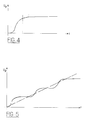
- the charging of the piezoelectric ceramic P i can be carried out at once as shown in FIG. 4 which represents the voltage U p across the terminals of P i as a function of time, or else in several successive stages as shown in the figure 5.
- the ascending part of each of the two curves corresponds to the first phase when the switch S w1 is closed and the bearing corresponds to the second phase when this same switch is commanded to open.
- the advantage of a loading in several stages is that it makes it possible to use components of reduced size and to vary the loading slope, approaching the curve of the voltage U p in the growth phase.
- the fuel injection then takes place as soon as the piezoelectric actuator has a voltage greater than 200 volts, depending on the type of injector.
- the switch S w1 is now commanded to be opened while the second switch S w2 is commanded successively upon closing and then upon opening.
- the switch S w2 is closed so that there is an energy transfer from the piezoelectric actuator P i which discharges towards the inductance L 2 creating a current I 2 in the second current loop described above.
- the capacitor C discharges into the battery B through the inductor L 1 , creating a current I 1 in the first current loop, as shown in the diagram equivalent to the discharge circuit of the actuator in FIG. 6.
- the switch S w2 is open so that the current l ' 1 accumulated in the inductor L 1 forces the conduction of the diode D 1 mounted in the passing direction, the battery B then continuing to recharge .
- the diode D 1 ensures the continuity of the conduction of the current l ' 2 in the inductance L 2 , current coming from the discharge of the actuator P i which continues to discharge through the diode D 1 , the capacitance C, and inductance L 2 , as shown in the diagram in FIG. 7. This current ensures the recharging of capacitance C.
- the charge of the actuator its discharge can be carried out in several successive stages which make it possible to control the slope and to reduce the size of the components, each stage corresponding to the opening of the switch S w2 .
- the charging of the piezoelectric actuator P i is carried out indirectly by discharging the capacitor C playing the role of energy accumulator, which is recharged by the voltage source B, and on the other apart from the discharge of the piezoelectric actuator P i is carried out indirectly in the capacitance C which it recharges thus, which will then discharge in the voltage source B.
- the mounting of this control device is reversible, which limits the number of components and therefore the overall cost of the assembly which is supplied by a low voltage battery on board the vehicle, delivering 12, 24 or 42 volts.
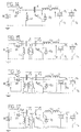
- FIG. 8 represents a second embodiment of the control device according to the invention, in which the two inductors L 1 and L 2 are coupled around a single core, the direction of their respective windings being symbolized by a star on the diagram.
- a low value inductor L connected in series with one of them, in this case L 1 , contributes to smoothing the currents.
- the advantage of this embodiment is that a single core is necessary for the two inductors L 1 and L 2 .
- FIG. 9 is a third embodiment of the control device according to the invention in which a transformer T is inserted in order to ensure galvanic isolation between the piezoelectric actuator and the low voltage source.
- a transformer is inserted in parallel between the two switches S w1 and S w2 provided that the previous capacity C, used as an energy accumulator, is divided into two capacities C 1 and C 2 , mounted on both sides of the transformer.
- One of the terminals of the primary winding T 1 is thus connected to the capacitor C 1 , the other terminal being connected to ground, while one of the terminals of the secondary winding T 2 is connected to the other capacitor C 2 and its other terminal is connected to ground.
- the switch S w1 is closed, the capacitor C 1 prevents the transformer primary from being short-circuited.
- the choice of the transformation ratio m between the primary and secondary windings makes it possible to adjust the loading of the piezoelectric actuator.
- the charging of the piezoelectric ceramic P i is carried out in two phases, the switch S w2 being open.
- the switch S w1 is closed: the inductance L 1 is charged, the voltage of 12 volts across the terminals of the battery B generates a higher voltage, of the order of 50 volts, across the terminals of the primary winding of the transformer T and the two capacitors C 1 and C 2 discharge, which ensures the charge of the actuator P i , as shown by the direction of the currents shown in solid lines.
- the switch S w1 is open, the capacitor C 1 is charged and the capacitor C 2 is charged by the diode D 2 .
- the inductance L 2 discharges into the actuator, as shown by the direction of the currents shown in dotted lines.
- a variant of this embodiment consists in coupling the windings of the transformer T to the two inductors L 1 and L 2 , as shown in FIG. 10, in order to use only a single magnetic circuit with a single core.
- the direction of the different windings is mentioned by a star on each of them.
- a low value inductor L is connected in series with the inductor L 1 or L 2 to smooth the currents, and is not coupled to the other windings.
- a fourth embodiment, represented in FIG. 11, carries out in the assembly connected to the battery B, a permutation of the inductance L 1 with the switch S w1 with respect to the first mode of FIG. 1.
- the switch S w1 mounted in parallel with the diode D 1 is connected to the positive terminal of the voltage source B and the inductance L 1 is connected to the junction point J 1 of the switch S w1 and of the capacitance C on the one hand and to ground on the other hand
- the switch S w2 of the second set connected to the actuator is connected to the junction point J 2 of the capacitance C and of the inductance L 2 of on the one hand and to earth on the other hand, with the freewheeling diode D 2 , mounted in parallel in the direction of the charging current of the piezoelectric actuator P i .
- the following embodiment combines the permutation of the inductance L 1 , closest to the battery B, with the first switch S w1 , and the coupling of the inductances L 1 and L 2 around the same magnetic core, an inductance L of low value, to smooth the currents, being connected in series with the inductor L 2 connected to the piezoelectric actuator P i for example, as shown in the diagram in FIG. 14.
- the last embodiment represented in FIG. 15, it combines the insertion of a transformer T in parallel between the two switches S w1 and S w2 with the permutation of the inductance L 1 , closest to the battery B, with the first switch S w1 , on condition that the preceding capacity C is divided into two capacities C 1 and C 2 , mounted on either side of the transformer.
- One of the terminals of the primary T 1 is thus connected to the capacitor C 1 , the other terminal being connected to ground, while one of the terminals of the secondary T 2 is connected to the other capacitor C 2 and its other terminal is connected to ground.
- FIG. 16 represents the diagram equivalent to the charging circuit of the piezoelectric ceramic, during the first of two successive charging phases.
- the switch S w1 being closed, the inductor L 1 charges, while the two capacitors C 1 and C 2 discharge. Thus, the actuator charges through the inductance L 2 .
- the switch S w1 is commanded to open so that, on the one hand, the capacitor C 1 is charged thanks to the energy stored in the inductance L 1 , and on the other hand the capacitor C 2 is charged by the diode D 2 which has turned on and the inductor L 2 is discharged through the piezoelectric actuator which thus continues to charge.
- the device according to the invention has the advantage of being made up of a very limited number of components, which reduces both its overall cost and its footprint. Another interesting advantage is linked to the loading of the actuator under adjustable voltages, with the possibility of controlling the slopes loading and unloading. In addition, this structure is reversible, ensuring both the loading and unloading of the actuator.
Landscapes
- Engineering & Computer Science (AREA)
- Chemical & Material Sciences (AREA)
- Combustion & Propulsion (AREA)
- Mechanical Engineering (AREA)
- General Engineering & Computer Science (AREA)
- Power Engineering (AREA)
- General Electrical Machinery Utilizing Piezoelectricity, Electrostriction Or Magnetostriction (AREA)
Applications Claiming Priority (2)
| Application Number | Priority Date | Filing Date | Title |
|---|---|---|---|
| FR0109148 | 2001-07-10 | ||
| FR0109148A FR2827440B1 (fr) | 2001-07-10 | 2001-07-10 | Dispositif de commande d'un actuateur piezo-electrique et son procede de mise en oeuvre |
Publications (2)
| Publication Number | Publication Date |
|---|---|
| EP1276159A1 true EP1276159A1 (de) | 2003-01-15 |
| EP1276159B1 EP1276159B1 (de) | 2007-09-12 |
Family
ID=8865323
Family Applications (1)
| Application Number | Title | Priority Date | Filing Date |
|---|---|---|---|
| EP02291682A Expired - Lifetime EP1276159B1 (de) | 2001-07-10 | 2002-07-05 | Ansteuerschaltung für einen piezoelektrischen Aktuator sowie Betriebsverfahren |
Country Status (3)
| Country | Link |
|---|---|
| EP (1) | EP1276159B1 (de) |
| DE (1) | DE60222338T2 (de) |
| FR (1) | FR2827440B1 (de) |
Cited By (4)
| Publication number | Priority date | Publication date | Assignee | Title |
|---|---|---|---|---|
| FR2851378A1 (fr) * | 2003-02-19 | 2004-08-20 | Siemens Ag | Etage de puissance de sortie pour charges capacitives |
| FR2899737A1 (fr) * | 2006-04-10 | 2007-10-12 | Renault Sas | Dispositif et procede de pilotage d'un actionneur piezo-electrique ultrasonore. |
| CN101902144B (zh) * | 2009-05-26 | 2013-04-17 | 研能科技股份有限公司 | 电压转换器及其所适用的驱动系统 |
| CN107269426A (zh) * | 2016-03-31 | 2017-10-20 | 大陆汽车有限公司 | 用于对压电致动器进行充电和放电的电路装置 |
Families Citing this family (3)
| Publication number | Priority date | Publication date | Assignee | Title |
|---|---|---|---|---|
| DE102004003836B4 (de) * | 2004-01-26 | 2006-05-04 | Siemens Ag | Schaltungsanordnung zum Aufladen und Entladen eines kapazitiven Stellglieds |
| DE102016117239A1 (de) | 2016-09-14 | 2018-03-15 | USound GmbH | Verfahren und Schaltung zum Betreiben eines Piezo-Bauteils sowie einen integrierten Schaltkreis mit einer derartigen Schaltung |
| CN110138269B (zh) * | 2019-05-06 | 2021-02-19 | 上海理工大学 | 用于多个压电陶瓷同步线性操作的电荷控制器 |
Citations (2)
| Publication number | Priority date | Publication date | Assignee | Title |
|---|---|---|---|---|
| GB2198604A (en) * | 1986-11-15 | 1988-06-15 | Brother Ind Ltd | Piezoelectric element drive circuit |
| GB2335317A (en) * | 1998-03-11 | 1999-09-15 | Simon Richard Greenwood | Bi-directional voltage converter |
-
2001
- 2001-07-10 FR FR0109148A patent/FR2827440B1/fr not_active Expired - Fee Related
-
2002
- 2002-07-05 DE DE60222338T patent/DE60222338T2/de not_active Expired - Lifetime
- 2002-07-05 EP EP02291682A patent/EP1276159B1/de not_active Expired - Lifetime
Patent Citations (2)
| Publication number | Priority date | Publication date | Assignee | Title |
|---|---|---|---|---|
| GB2198604A (en) * | 1986-11-15 | 1988-06-15 | Brother Ind Ltd | Piezoelectric element drive circuit |
| GB2335317A (en) * | 1998-03-11 | 1999-09-15 | Simon Richard Greenwood | Bi-directional voltage converter |
Cited By (8)
| Publication number | Priority date | Publication date | Assignee | Title |
|---|---|---|---|---|
| FR2851378A1 (fr) * | 2003-02-19 | 2004-08-20 | Siemens Ag | Etage de puissance de sortie pour charges capacitives |
| FR2899737A1 (fr) * | 2006-04-10 | 2007-10-12 | Renault Sas | Dispositif et procede de pilotage d'un actionneur piezo-electrique ultrasonore. |
| WO2007116159A1 (fr) * | 2006-04-10 | 2007-10-18 | Renault S.A.S | Dispositif et procede de pilotage d'un actionneur piezo-electrique ultrasonore |
| US7944117B2 (en) | 2006-04-10 | 2011-05-17 | Renault S.A.S | Device and method for driving an ultrasound piezoelectric actuator |
| CN101902144B (zh) * | 2009-05-26 | 2013-04-17 | 研能科技股份有限公司 | 电压转换器及其所适用的驱动系统 |
| CN107269426A (zh) * | 2016-03-31 | 2017-10-20 | 大陆汽车有限公司 | 用于对压电致动器进行充电和放电的电路装置 |
| CN107269426B (zh) * | 2016-03-31 | 2020-02-07 | 大陆汽车有限公司 | 用于对压电致动器进行充电和放电的电路装置 |
| US10636956B2 (en) | 2016-03-31 | 2020-04-28 | Vitesco Technologies GmbH | Circuit arrangement for charging and discharging a piezo actuator |
Also Published As
| Publication number | Publication date |
|---|---|
| FR2827440A1 (fr) | 2003-01-17 |
| FR2827440B1 (fr) | 2003-10-03 |
| EP1276159B1 (de) | 2007-09-12 |
| DE60222338D1 (de) | 2007-10-25 |
| DE60222338T2 (de) | 2008-06-12 |
Similar Documents
| Publication | Publication Date | Title |
|---|---|---|
| FR3001089A1 (fr) | Equilibrage de charge dans une batterie electrique | |
| EP0409747A1 (de) | Gate-Steuerschaltung für einen MOS-Transistor | |
| EP1368884A2 (de) | Kommutierungshilfsschaltung für ein schaltnetzteil | |
| FR2923962A1 (fr) | Circuit elevateur de tension | |
| FR2969850A1 (fr) | Convertisseur d'equilibrage des cellules d'une batterie electrique | |
| EP1276159B1 (de) | Ansteuerschaltung für einen piezoelektrischen Aktuator sowie Betriebsverfahren | |
| WO2008074951A1 (fr) | Dispositif de pre-charge de moyens de stockage d'energie associes a une machne electrique tournante | |
| FR2829314A1 (fr) | Dispositif de commande d'un actuateur piezo-electrique et son procede de mise en oeuvre | |
| EP0977346A1 (de) | Gleichstrom-Gleichstromwandler | |
| EP1953904A1 (de) | Dämpferschaltung für einen Schaltkonverter | |
| WO2019110297A1 (fr) | Convertisseur continu-continu avec pre-charge d'un premier reseau electrique a partir d'un deuxieme reseau electrique | |
| FR2831727A1 (fr) | Dispositif de commande d'un actuateur piezo-electrique ultrasonore pilote electroniquement, et son procede de mise en oeuvre | |
| EP4252342A1 (de) | Batterieladegerät für kraftfahrzeug, entsprechendes fahrzeug und umsetzungsverfahren | |
| EP1522700A2 (de) | spannungserhohungsschaltung für einen piezoelektrischen Aktor eines Einspritzventils | |
| EP1929630B1 (de) | Strikte steuerung elektrischer stromumsetzer | |
| FR2829313A1 (fr) | Dispositif de commande d'un actuateur piezo-electrique et son procede de mise en oeuvre | |
| FR2851378A1 (fr) | Etage de puissance de sortie pour charges capacitives | |
| FR3039934A1 (fr) | Procede de gestion de l’alimentation electrique d’un vehicule automobile | |
| EP3871237A1 (de) | Elektromagnetische induktionsvorrichtung | |
| EP3195459B1 (de) | Gleichspannungswandler und zugehöriges steuerungsverfahren | |
| FR2858907A1 (fr) | Circuit d'eclairage a lampe a decharge | |
| WO2006056363A1 (fr) | Convertisseur continu-continu a plusieurs sorties | |
| FR3066866B1 (fr) | Convertisseur continu-continu pour vehicule electrique ou hybride | |
| EP2260519B1 (de) | Vorrichtung zur steuerung eines piezoelektrischen ultraschallaktuators | |
| FR3166584A1 (fr) | Procédé de recharge d’un véhicule électrique avec une borne de recharge de tension maximale supérieure ou inférieure à une tension maximale d’une batterie du véhicule |
Legal Events
| Date | Code | Title | Description |
|---|---|---|---|
| PUAI | Public reference made under article 153(3) epc to a published international application that has entered the european phase |
Free format text: ORIGINAL CODE: 0009012 |
|
| AK | Designated contracting states |
Kind code of ref document: A1 Designated state(s): AT BE BG CH CY CZ DE DK EE ES FI FR GB GR IE IT LI LU MC NL PT SE SK TR |
|
| AX | Request for extension of the european patent |
Free format text: AL;LT;LV;MK;RO;SI |
|
| 17P | Request for examination filed |
Effective date: 20030717 |
|
| AKX | Designation fees paid |
Designated state(s): AT BE BG CH CY LI |
|
| RBV | Designated contracting states (corrected) |
Designated state(s): BE DE ES GB IT |
|
| REG | Reference to a national code |
Ref country code: DE Ref legal event code: 8566 |
|
| 17Q | First examination report despatched |
Effective date: 20060322 |
|
| GRAP | Despatch of communication of intention to grant a patent |
Free format text: ORIGINAL CODE: EPIDOSNIGR1 |
|
| GRAS | Grant fee paid |
Free format text: ORIGINAL CODE: EPIDOSNIGR3 |
|
| GRAA | (expected) grant |
Free format text: ORIGINAL CODE: 0009210 |
|
| AK | Designated contracting states |
Kind code of ref document: B1 Designated state(s): BE DE ES GB IT |
|
| REG | Reference to a national code |
Ref country code: GB Ref legal event code: FG4D Free format text: NOT ENGLISH |
|
| REF | Corresponds to: |
Ref document number: 60222338 Country of ref document: DE Date of ref document: 20071025 Kind code of ref document: P |
|
| GBV | Gb: ep patent (uk) treated as always having been void in accordance with gb section 77(7)/1977 [no translation filed] | ||
| PG25 | Lapsed in a contracting state [announced via postgrant information from national office to epo] |
Ref country code: ES Free format text: LAPSE BECAUSE OF FAILURE TO SUBMIT A TRANSLATION OF THE DESCRIPTION OR TO PAY THE FEE WITHIN THE PRESCRIBED TIME-LIMIT Effective date: 20071223 |
|
| PG25 | Lapsed in a contracting state [announced via postgrant information from national office to epo] |
Ref country code: GB Free format text: LAPSE BECAUSE OF FAILURE TO SUBMIT A TRANSLATION OF THE DESCRIPTION OR TO PAY THE FEE WITHIN THE PRESCRIBED TIME-LIMIT Effective date: 20070912 |
|
| PLBE | No opposition filed within time limit |
Free format text: ORIGINAL CODE: 0009261 |
|
| STAA | Information on the status of an ep patent application or granted ep patent |
Free format text: STATUS: NO OPPOSITION FILED WITHIN TIME LIMIT |
|
| 26N | No opposition filed |
Effective date: 20080613 |
|
| PG25 | Lapsed in a contracting state [announced via postgrant information from national office to epo] |
Ref country code: BE Free format text: LAPSE BECAUSE OF NON-PAYMENT OF DUE FEES Effective date: 20080731 |
|
| PG25 | Lapsed in a contracting state [announced via postgrant information from national office to epo] |
Ref country code: IT Free format text: LAPSE BECAUSE OF NON-PAYMENT OF DUE FEES Effective date: 20080731 |
|
| PGFP | Annual fee paid to national office [announced via postgrant information from national office to epo] |
Ref country code: DE Payment date: 20160722 Year of fee payment: 15 |
|
| REG | Reference to a national code |
Ref country code: DE Ref legal event code: R119 Ref document number: 60222338 Country of ref document: DE |
|
| PG25 | Lapsed in a contracting state [announced via postgrant information from national office to epo] |
Ref country code: DE Free format text: LAPSE BECAUSE OF NON-PAYMENT OF DUE FEES Effective date: 20180201 |