EP1276176A2 - Verbinder mit Schutzkappe - Google Patents
Verbinder mit Schutzkappe Download PDFInfo
- Publication number
- EP1276176A2 EP1276176A2 EP02014866A EP02014866A EP1276176A2 EP 1276176 A2 EP1276176 A2 EP 1276176A2 EP 02014866 A EP02014866 A EP 02014866A EP 02014866 A EP02014866 A EP 02014866A EP 1276176 A2 EP1276176 A2 EP 1276176A2
- Authority
- EP
- European Patent Office
- Prior art keywords
- type connector
- shutter
- housing
- terminals
- plug type
- Prior art date
- Legal status (The legal status is an assumption and is not a legal conclusion. Google has not performed a legal analysis and makes no representation as to the accuracy of the status listed.)
- Granted
Links
- 229920005989 resin Polymers 0.000 claims abstract description 11
- 239000011347 resin Substances 0.000 claims abstract description 11
- 239000000463 material Substances 0.000 claims abstract description 8
- 238000003780 insertion Methods 0.000 claims description 57
- 230000037431 insertion Effects 0.000 claims description 57
- 238000000605 extraction Methods 0.000 claims description 51
- 210000000078 claw Anatomy 0.000 claims description 44
- 239000002184 metal Substances 0.000 claims description 14
- 239000004020 conductor Substances 0.000 claims description 9
- 230000002093 peripheral effect Effects 0.000 claims description 4
- 238000000926 separation method Methods 0.000 claims description 2
- 238000009413 insulation Methods 0.000 abstract 1
- 238000010292 electrical insulation Methods 0.000 description 10
- 239000000428 dust Substances 0.000 description 7
- 230000000903 blocking effect Effects 0.000 description 4
- 238000004519 manufacturing process Methods 0.000 description 4
- 238000000465 moulding Methods 0.000 description 4
- 230000002035 prolonged effect Effects 0.000 description 4
- 229920003002 synthetic resin Polymers 0.000 description 4
- 239000000057 synthetic resin Substances 0.000 description 4
- 230000008901 benefit Effects 0.000 description 3
- 230000002708 enhancing effect Effects 0.000 description 3
- 230000004048 modification Effects 0.000 description 3
- 238000012986 modification Methods 0.000 description 3
- 239000011248 coating agent Substances 0.000 description 2
- 238000000576 coating method Methods 0.000 description 2
- 238000005520 cutting process Methods 0.000 description 2
- 239000007769 metal material Substances 0.000 description 2
- 238000000034 method Methods 0.000 description 2
- 230000008569 process Effects 0.000 description 2
- 238000005452 bending Methods 0.000 description 1
- 230000008859 change Effects 0.000 description 1
- 238000004140 cleaning Methods 0.000 description 1
- 230000008878 coupling Effects 0.000 description 1
- 238000010168 coupling process Methods 0.000 description 1
- 238000005859 coupling reaction Methods 0.000 description 1
- 230000000694 effects Effects 0.000 description 1
- 229920001971 elastomer Polymers 0.000 description 1
- 239000000806 elastomer Substances 0.000 description 1
- 230000001771 impaired effect Effects 0.000 description 1
- 238000009434 installation Methods 0.000 description 1
- 238000010297 mechanical methods and process Methods 0.000 description 1
- 230000005226 mechanical processes and functions Effects 0.000 description 1
Images






Classifications
-
- H—ELECTRICITY
- H01—ELECTRIC ELEMENTS
- H01R—ELECTRICALLY-CONDUCTIVE CONNECTIONS; STRUCTURAL ASSOCIATIONS OF A PLURALITY OF MUTUALLY-INSULATED ELECTRICAL CONNECTING ELEMENTS; COUPLING DEVICES; CURRENT COLLECTORS
- H01R13/00—Details of coupling devices of the kinds covered by groups H01R12/70 or H01R24/00 - H01R33/00
- H01R13/44—Means for preventing access to live contacts
- H01R13/447—Shutter or cover plate
- H01R13/453—Shutter or cover plate opened by engagement of counterpart
- H01R13/4538—Covers sliding or withdrawing in the direction of engagement
-
- H—ELECTRICITY
- H01—ELECTRIC ELEMENTS
- H01R—ELECTRICALLY-CONDUCTIVE CONNECTIONS; STRUCTURAL ASSOCIATIONS OF A PLURALITY OF MUTUALLY-INSULATED ELECTRICAL CONNECTING ELEMENTS; COUPLING DEVICES; CURRENT COLLECTORS
- H01R13/00—Details of coupling devices of the kinds covered by groups H01R12/70 or H01R24/00 - H01R33/00
- H01R13/46—Bases; Cases
- H01R13/52—Dustproof, splashproof, drip-proof, waterproof, or flameproof cases
-
- H—ELECTRICITY
- H01—ELECTRIC ELEMENTS
- H01R—ELECTRICALLY-CONDUCTIVE CONNECTIONS; STRUCTURAL ASSOCIATIONS OF A PLURALITY OF MUTUALLY-INSULATED ELECTRICAL CONNECTING ELEMENTS; COUPLING DEVICES; CURRENT COLLECTORS
- H01R13/00—Details of coupling devices of the kinds covered by groups H01R12/70 or H01R24/00 - H01R33/00
- H01R13/648—Protective earth or shield arrangements on coupling devices, e.g. anti-static shielding
- H01R13/6485—Electrostatic discharge protection
-
- H—ELECTRICITY
- H01—ELECTRIC ELEMENTS
- H01R—ELECTRICALLY-CONDUCTIVE CONNECTIONS; STRUCTURAL ASSOCIATIONS OF A PLURALITY OF MUTUALLY-INSULATED ELECTRICAL CONNECTING ELEMENTS; COUPLING DEVICES; CURRENT COLLECTORS
- H01R2201/00—Connectors or connections adapted for particular applications
- H01R2201/16—Connectors or connections adapted for particular applications for telephony
-
- H—ELECTRICITY
- H01—ELECTRIC ELEMENTS
- H01R—ELECTRICALLY-CONDUCTIVE CONNECTIONS; STRUCTURAL ASSOCIATIONS OF A PLURALITY OF MUTUALLY-INSULATED ELECTRICAL CONNECTING ELEMENTS; COUPLING DEVICES; CURRENT COLLECTORS
- H01R24/00—Two-part coupling devices, or either of their cooperating parts, characterised by their overall structure
- H01R24/60—Contacts spaced along planar side wall transverse to longitudinal axis of engagement
- H01R24/62—Sliding engagements with one side only, e.g. modular jack coupling devices
Definitions
- the present invention relates to a jack type connector with a shutter, and more particularly to a jack type connector with a thin shutter which is to be used in, for example, an IO port of a mobile terminal device such as a portable telephone.
- a jack type connector with a shutter of the invention countermeasures for dustproof during a non-use period, and for preventing electrostatic discharge damage of electronic devices connected to internal terminals from occurring are taken, and also a countermeasure for enhancing electrical insulation among the internal terminals is taken.
- a countermeasure for preventing the plug type connector from slipping from the jack type connector and damaging the connectors is taken.
- Japanese Utility Model Application Laying-Open No. 6-50270 discloses a small connector that is a jack type connector in which a countermeasure for dustproof is taken.
- the connector has a housing which accommodates terminals overlaid on an inner wall face, and a slider which is disposed in the housing so as to be slidable between a closing position where the slider closes a plug fitting hole of the housing, and an opening position which is in rear of the closing position.
- the slider is always elastically urged toward the closing position.
- the slider has slide terminals which, in the closing position, are in contact with the terminals, and which, in the opening position, separate from the terminals.
- the slide terminals separate from the housing terminals, it is possible to detect that the counter connector is inserted into the fitting hole.
- a contact is provided in a protrusion portion which is to be inserted into the jack type connector, and the protrusion portion pushes the slide of the jack type connector to cause the contact to be in contact with a contact of the counter connector.
- Japanese Utility Model Registration No. 2601800 discloses a jack type connector.
- a housing which accommodates terminals is surrounded by a shield frame, and a cover for opening and closing a plug insertion hole of the housing is formed by an electrically conductive member made of a metal material.
- an electrically conductive member made of a metal material.
- Japanese Utility Model Application Laying-Open No. 6-54260 discloses a jack type connector in which a housing which accommodates terminals is surrounded by a shield frame, and a shutter for closing a plug insertion hole of the housing is formed by an electrically conductive member made of a metal material.
- the shutter is always connected to the shield frame irrespective of the state of the shutter, or both in the opening and closing states.
- the slider is moved forward or backward in the housing to open or close the housing. Therefore, it is required only to ensure a space for accommodating the slider in the opening state, in a rear portion of the housing, and it is not required to ensure a space for accommodating the slider in the opening state, in an upper or lower side of the housing, thereby producing an advantage that the housing can be easily thinned.
- a molded product of a synthetic resin is used as the slider, and the slider itself does not have a property of shielding the terminals accommodated in the housing from electromagnetic waves.
- the housing is incorporated into, for example, a mobile terminal device and the terminals accommodated in the housing are electrically connected to electronic devices of the mobile terminal device, even when the fitting hole of the housing is closed by the slider during a non-use period in which the plug type connector is not inserted into the housing, therefore, external electromagnetic waves are not blocked by the slider and influence the terminals and in turn the electronic devices. As a result, there arises the possibility that electrostatic discharge damage occurs in the electronic devices.
- the cover or the shutter (hereinafter, such a component is referred to as "shutter or the like") is pushed by the counter connector to swing in the opening direction about a horizontal shaft, and accommodated so as to be overlaid on the upper or lower wall of the housing, with the result that the shutter is sandwiched between the plug type connector and the upper or lower wall of the housing. Therefore, a space for accommodating the shutter or the like in the opening state must be ensured in an upper or lower side of the housing. This impedes the thinning of the housing.
- the shutter or the like is formed by an electrically conductive metal member, and, at least in the closing state, the shutter or the like is electrically connected to the shield frame surrounding the housing.
- the shutter or the like exerts the function of blocking external electromagnetic waves, thereby producing an advantage that the terminals housed in the housing, and the electronic devices which are electrically connected to the terminals are prevented from suffering electrostatic discharge damage.
- the shutter or the like may be contemplated to divide the shutter or the like into a portion having conductivity which is required for providing the function of blocking electromagnetic waves, and mechanic portions such as a boss, form the conductive portion by a metal member, and insert-mold the metal member together with a synthetic resin portion for forming the mechanic portions.
- this causes a further problem in that the charges for a mold and the molding are raised and hence the production cost is increased as a whole.
- a countermeasure for dustproof is taken by enabling a cover formed by a molded product of a synthetic resin such as elastomer which is a dielectric, to be attached and detached.
- a countermeasure for preventing electrostatic discharge damage when such a multipolar connector is not used is particularly taken.
- the invention has been conducted in view of the above-discussed situation.
- jack type connector with a shutter of the invention will be described.
- the reference numerals shown in the figures are used in order to facilitate the understanding of the invention. The use of the reference numerals is not intended as restricting the invention to the illustrated example.
- the jack type connector B with a shutter of the invention comprises: a housing 1 which has an insertion/extraction port 20 for a plug type connector A serving as a counter connector, and which accommodates a large number of internal terminals 3 that are to be in contact with terminals of the plug type connector A inserted into the insertion/extraction port 20; and a shutter 5 which is closed and opened in an internal space of the housing 1 and between a closing position where the shutter closes the insertion/extraction port 20, and an opening position where the shutter opens the insertion/extraction port 20.
- the jack type connector with a shutter is useful as a connector which is to be incorporated into a mobile terminal device such as a portable telephone.
- the jack type connector with a shutter of the invention has: the shutter 5 which is electrically conductive; means (a spring member 55) for always elastically urging the shutter 5 toward the closing position; and a grounding contact piece 41 which is disposed in the housing so that, when the shutter 5 is at the closing position, a butting portion 52a constituting a part of the shutter 5 is in contact with the grounding contact piece, and, when the shutter 5 is opened from the closing position toward the opening position, the butting portion 52a separates from the grounding contact piece.
- the grounding contact piece 41 may be accommodated in the housing 1.
- the grounding contact piece 41 may be formed by a shield case 45 which is placed outside the housing 1 to cover the housing 1.
- the shutter is formed by a shutter body which is configured by a resin molded product, and a metal sheet which is attached to a front face of the shutter body, and the butting portion is provided in the metal sheet.
- the shutter 5 is at the closing position to close the insertion/extraction port 20, and hence dust does not enter through the insertion/extraction port 20 into the housing 1, whereby the internal terminals 3 and the grounding contact piece 41 which are accommodated in the housing 1 are prevented from being contaminated with dust.
- the contact stability of the terminals of the plug type connector A, and the butting portion 52a with respect to the internal terminals and the grounding contact piece is improved.
- the shutter 5 Since the shutter 5 is electrically conductive and, when the shutter 5 is at the closing position, the butting portion 52a constituting a part of the shutter 5 is in contact with the grounding contact piece 41, the shutter 5 itself exhibits the electromagnetic wave shielding performance to block external electromagnetic waves. Therefore, the internal terminals 3 which are accommodated in the housing 1, electronic devices which are electrically connected to the internal terminals 3, and the like are prevented from suffering electrostatic discharge damage.
- the shutter 5 is integrally molded by an electrically conductive resin material.
- the shutter 5 can be integrally molded easily and economically, and letters and/or symbols can be engraved on a molding die so that they can be three-dimensionally indicated on the surface of the shutter 5.
- the conductive resin material is appropriately toned, the shutter 5 can be colored without conducting a coating operation. Therefore, the design and color of the shutter 5 can be easily matched for the appearance of a mobile terminal device into which the jack type connector is to be incorporated.
- the housing 1 is configured in the following manner.
- the housing 1 has a box-like hollow shape which laterally elongates.
- a large number of recesses 21 are laterally arranged in plural places of a bottom wall 13 of the housing 1.
- Each of the recesses is surrounded by a front ridge 22 which is disposed in a front edge of the bottom wall 13, and which laterally elongates, and right and left side ridges 23 which elongate from the front ridge 22 toward a rear side of the bottom wall 13.
- the internal terminals 3 are accommodated in the recesses 21, respectively.
- Upper end faces of the front ridge 22 and the side ridges 23 are higher in level than upper faces of the internal terminals 3.
- a protrusion 54 for ensuring a gap space between a lower end edge of the shutter 5 and the internal terminals 3 is projected from the lower end edge of the shutter 5, or the front ridge 22.
- a gap space S for enhancing the electrical insulation between the lower end edge of the shutter 5 and the internal terminals 3 is ensured, and the creepage distance between the internal terminals 3 and the shutter 5 is prolonged, so that the performance stability is further improved.
- the protrusion 54 may be projected from only the lower end edge of the shutter 5, only the front ridge, or both the lower end edge of the shutter and the front ridge.
- the invention may be configured in the following manner.
- a plate-like conductor 4 is accommodated in a recess 19 which is formed in a wall face of a lateral end portion of the housing 1.
- the grounding contact piece 41 which is upward projected in the recess 19 is formed integrally with a front end portion of the conductor 4.
- An engagement claw 51 is disposed on a lateral end portion of the shutter 5. When the shutter 5 is at the closing position, the engagement claw is engaged with a rear end face 41a of the grounding contact piece 41. When the shutter 5 is opened from the closing position toward the opening position, the engagement claw separates from the rear end face 41a of the grounding contact piece 41.
- An engagement/disengagement portion of the engagement claw 51 with respect to the rear end face 41a of the grounding contact piece 41 is formed as the butting portion 52a.
- the engagement between the engagement claw 51 and the rear end face 41a of the grounding contact piece 41 can prevent a situation in which the shutter 5 slips from the housing 1, from occurring. Therefore, it is not required to additionally dispose means for preventing the shutter 5 from slipping off, and hence the structure is correspondingly simplified. Since the butting portion 52a is formed on the engagement claw 51 which performs the slipping-off preventing function, it is not required to additionally dispose the butting portion 52a, whereby the structure is further simplified.
- the shutter 5 is longitudinally movably accommodated in the housing 1, directions of opening and closing the shutter 5 coincide respectively with longitudinal directions of the housing 1, and a spring member 55 which always elastically urges the shutter 5 toward the closing position is interposed between the shutter 5 and a rear end wall 16 of the housing 1.
- the shutter 5 is simply longitudinally moved in the housing 1 so as to be opened or closed, and hence the space for accommodating the shutter in the opening state is required only to be ensured in the rear portion of the housing 1. Since it is not required to ensure a space for accommodating the shutter in the opening state in the upper or lower side of the housing 1, the housing 1 can be easily thinned.
- the function of dustproof during a non-use period is effectively performed by the shutter, and, during a non-use period, the shutter itself remarkably performs the function of blocking external electromagnetic waves to prevent electrostatic discharge damage of internal terminals accommodated in the housing, and electronic devices which are in a mobile terminal device or the like, and which are electrically connected to the internal terminals, from occurring.
- the shutter can be economically produced by a molding process using an electrically conductive resin material, and hence the production cost of the jack type connector can be easily reduced. Letters and/or symbols can be easily indicated on the shutter, so that the design of the connector can be easily enhanced.
- the shutter itself is provided with electrical conductivity, an effect that electrical insulation among the many internal terminals that are densely accommodated in the housing can be easily enhanced is attained.
- the above-described jack type connector B which laterally elongates is used as the counter connector.
- the plug type connector A of the invention has: terminals 73 which are to be inserted into an internal space S1 of the jack type connector B that laterally elongates and serves as a counter connector, through the insertion/extraction port 20 that laterally elongates and has a rectangular shape, whereby the terminals are caused to be respectively in contact with the internal terminals 3 of the jack type connector B; a butting portion 63a which butts against a receiving portion 24a of the jack type connector B to restrict a degree of insertion of the terminals 73 with respect to the internal space S1; and protrusion portions 8 which are projected in front of the terminals 73, and which, when the terminals 73 are inserted into the internal space S1 of the jack type connector B through the insertion/extraction port 20, pushes open the shutter 5 which closes the insertion/extraction port 20 of the jack type connector B.
- the protrusion portions 8 have a shape which, in accordance with a tilting motion of the plug type connector A caused by prying the plug type connector in a thickness direction, allows the protrusion portions 8 to escape to an outside of the internal space S1 through the insertion/extraction port 20 without changing an initial shape of peripheral wall faces of the internal space S1, and an initial shape of the shutter 5 which is opened by the protrusion portions 8, and the internal terminals 3 of the jack type connector B are placed outside loci of movement in which the protrusion portions 8 escape to the outside of the internal space S1 through the insertion/extraction port 20.
- the protrusion portions 8 inserted into the jack type connector B can escape therefrom without damaging the jack type connector B and the shutter 5, and there is no possibility that the internal terminals 3 of the jack type connector B are damaged. Moreover, there is no possibility that the internal terminals 3 are damaged.
- the insertion/extraction port 20 of the jack type connector B is opened in a front end of the housing 1 of the jack type connector B, the receiving portion 24a is formed by a front end face of the housing 1, the front end face forming an edge portion of the insertion/extraction port 20, the butting portion 63a is formed by a front end face of the plug type connector A, and, when the plug type connector A is pried in the thickness direction T under a state where the butting portion 63a butts against the receiving portion 24a, the plug type connector A is tilted with using one place of butting areas between the butting portion 63a and the receiving portion 24a as a fulcrum P1 or P2, the one place being in the thickness direction T of the plug type connector A.
- a shape of the protrusion portions 8 which are inserted into the internal space S1 of the jack type connector B to push open the shutter 5 is determined so that the protrusion portions are positioned inside a virtual circle R1 or R2 which is centered at the fulcrum P1 or P2, and which has a radius elongating from a position of the fulcrum to the edge of the insertion/extraction port 20, the edge being in a remoter side from the position of the fulcrum.
- a position of each of outer edges on both sides in a thickness direction of the front end face of the jack type connector B which butts against a rectangular and laterally elongating front end face 63 of a housing 6 of the plug type connector A is assumed as the position of the fulcrum of the prying and tilting of the plug type connector A, and a shape of the protrusion portions 8 is determined so that the protrusion portions are positioned inside the virtual circle R1 which is centered at the one fulcrum P1 that is assumed by the position of the one of the outer edges on both the sides in the thickness direction, and which has the radius elongating to the edge of the insertion/extraction port 20, the edge being in a remoter side from the position of the one fulcrum, and inside the virtual circle R2 which is centered at the other fulcrum P2 that is assumed by the position of the other outer edge, and which has a radius elongating to the edge of the insertion/extraction port 20, the edge being in a remoter
- contact pieces 7 are incorporated in the housing 6 of the plug type connector A, the terminals 73 which are formed into a protruding arcuate shape are disposed in front ends of the contact pieces 7, respectively, each of the terminals 73 is projected outside the outer profile line L of the corresponding one of the protrusion portions 8, between the front end face 63 of the housing 6 of the plug type connector A, and a front end 81 of the protrusion portion 8, and the internal terminals 3 of the jack type connector B are arranged so as to be overlaid on an inner face of the housing 1 of the jack type connector B in the thickness direction of the jack type connector B.
- the contact pieces 7 are elastically deformable in the thickness direction of the plug type connector A.
- the housing 1 of the jack type connector B, and the housing 6 of the plug type connector A are provided with an engagement claw 92 and an engagement face 25, respectively, the engagement claw 92 and the engagement face 25 engaging with each other when the butting portion 63a butts against the receiving portion 24a, the engagement between the engagement claw 92 and the engagement face 25 being canceled in accordance with separation of the butting portion 63a from the receiving portion 24a, and, when the plug type connector A is pried and tilted in the thickness direction, a locus of movement of the engagement claw 92 in which the engagement with the engagement face 25 is canceled is inside relief recesses 26 which are formed on both sides of the engagement face 25, respectively.
- the engagement claw 92 is disposed at a tip end of an elastically deformable rod 91 which is disposed on the housing 6 of the plug type connector A, and the engagement claw 92 comprises an inclined guide face 94 which slides over an edge of one of the relief recesses 26 to override the edge.
- Figs. 1 to 8 show an embodiment of the jack type connector with a shutter.
- a flat hollow housing 1 which laterally elongates comprises integrally an engagement portion 12 for preventing a plug type connector A (see Figs. 6 and 7) serving as counter connector from slipping off, in each of the lateral ends of the housing.
- the housing 1 is configured by an integral molded product of a synthetic resin having an excellent electrical insulation property.
- the housing has: a bottom wall 13; an upper wall 14 which is opposed to the bottom wall 13; right and left end walls 15 which couple the bottom wall 13 and the upper wall 14 at the right and left ends; and a rear wall 16.
- a lower portion of the rear wall 16 is recessed to form a recessed portion 16a which defines a contact piece accommodating space 17.
- recesses 21 which are laterally arranged are formed in plural equally-spaced places of the bottom wall 13.
- Each of the recesses 21 is surrounded to be formed into a rectangular shape, by: a front ridge 22 which is disposed in a front edge of the bottom wall 13, and which laterally elongates; right and left side ridges 23 which elongate from the front ridge 22 toward a rear side of the bottom wall 13; and the recessed portion 16a of the rear wall 16.
- Thin plate-like terminals 3 are accommodated in the recesses 21, respectively.
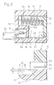
- the ridges 22 and 23 have the same height which is slightly larger than the thickness of the terminals 3. Therefore, the upper end faces of the front ridge 22 and the right and left side ridges 23 are located at a position which is higher in level by a dimension H than the upper faces of the terminals 3 that are overlaid on the bottom faces of the recesses 21 (see Fig. 2).
- an extension 32 having a folded contact piece 31 is continuously integrated with each of the terminals 3 so as to rearward elongate.
- the extension 32 elongates into the contact piece accommodating space 17 through a hole 18 formed in the rear wall 16, and the contact piece 31 is accommodated in the contact piece accommodating space 17.
- the terminals 3 each integrated with the contact piece 31 are placed in the recess 21 through the hole 18 from the back (rear) of the housing 1.
- a recess 19 is formed so as to extend from the rear end of the end wall 15 to a position in the vicinity of the front end.
- a plate-like conductor 4 is fitted into the recess 19.
- the conductor 4 has a grounding contact piece 41 which upward protrudes from the front end portion of the conductor into the recess 19, and a connecting terminal 42 in a rear end portion.
- the connecting terminal 42 can be connected to a grounding circuit which is not shown.
- the housing 1 comprises a shutter 5 which is longitudinally slid to be closed and opened in the internal space of the housing and between the closing position where the shutter closes the insertion/extraction port 20, and the opening position where the shutter opens the insertion/extraction port 20.
- the shutter 5 is configured so as to be closed and opened by longitudinal sliding operations, it is required only to ensure a space for accommodating the shutter in the opening state, in a rear portion of the housing 1, and it is not required to ensure a space for accommodating the shutter in the opening state, in an upper or lower side of the housing 1. Therefore, the housing can be easily thinned.
- the shutter 5 is integrally molded by an electrically conductive resin material.
- Engagement claws 51 are rearward projected from right and left (lateral) end portions of the shutter, respectively.
- each of the engagement claws 51 is provided with a claw piece 52 which is laterally outward projected.
- the claw piece 52 is accommodated in the recess 19 above the conductor 4 so as to be opposed to a rear end face 41a of the grounding contact piece 41.
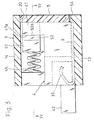
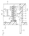
- the front end face of the claw piece 52 is engaged with the rear end face 41a of the grounding contact piece 41 as shown in Fig. 3 or 4, thereby preventing the shutter 5 from slipping from the housing 1.
- the grounding contact piece 41 is in contact with the shutter 5 to be electrically connected therewith.
- the front end face of the claw piece 52 separates from the rear end face 41a of the grounding contact piece 41, thereby canceling the electrical connection state between the grounding contact piece 41 and the shutter 5. Therefore, the front end face of the claw piece 52 corresponds to an engagement/disengagement portion with respect to the rear end face of the grounding contact piece 41, and serves as a butting portion 52a with respect to the grounding contact piece 41.
- a spring member 55 configured by a coil spring is interposed between the shutter 5 and the rear wall 16 of the housing 1. The shutter 5 is always elastically urged toward the closing position by the spring member 55.
- a protrusion 54 for ensuring a gap space S between the lower end edge 53 of the shutter 5 and the terminals 3 is downward projected from the lower end of a lateral end portion of the shutter 5.
- the protrusion 54 is disposed on the lower end of the lateral end portion of the shutter 5 in this way to ensure the gap space S between the lower end edge 53 of the shutter 5 and the terminals 3, the electrical insulation between the lower end edge 53 of the shutter 5 and the terminals 3 is improved, and the creepage distance between the terminals 3 and the shutter 5 is prolonged.
- the shutter 5 is electrically conductive, therefore, there never occurs a situation in which the terminals 3 that are laterally arranged are short-circuited and an erroneous signal is generated.
- the shutter 5 which is elastically urged by the spring member 55 as shown in Figs. 2 to 4 is at the closing position to close the insertion/extraction port 20. Therefore, dust does not enter through the insertion/extraction port 20 into the housing 1, so that the terminals 3 and the grounding contact piece 41 which are accommodated in the housing 1 are prevented from being contaminated with dust. Since the butting portion 52a of the engagement claw 51 is in contact with the grounding contact piece 41, the shutter 5 itself which has the engagement claw 51 exhibits the electromagnetic wave shielding performance to block external electromagnetic waves.
- the terminals which are accommodated in the housing, electronic devices which are electrically connected to the terminals, and the like are prevented from suffering electrostatic discharge damage.
- the shutter 5 When the plug type connector A (phantom line) is inserted into the insertion/extraction port 20 as indicated by the arrow P in Figs. 6 and 7, the shutter 5 is rearward pushed from the closing position toward the opening position by the plug type connector A against the urging by the spring member 55, and in accordance with this the butting portion 52a separates from the grounding contact piece 41.
- a large number of terminals (not shown) of the plug type connector A are in contact with the terminals 3, respectively.
- the shutter 5 is integrally molded by an electrically conductive resin material, letters and/or symbols can be three-dimensionally indicated on the surface of the shutter 5, simply by engraving them on a die for molding the shutter.
- the conductive resin material is appropriately toned, the shutter 5 can be colored without conducting a coating operation. Therefore, the design and color of the shutter 5 can be easily matched for the appearance of a mobile terminal device into which the multipolar connector is to be incorporated.
- the protrusion 54 for ensuring the gap space S between the lower end edge 53 of the shutter 5 and the terminals 3 is downward projected from the lower end of a lateral end portion of the shutter 5, thereby enhancing the electrical insulation between the conductive shutter 5 and the terminals.
- This can be realized also by employing another configuration.
- Fig. 8 is an enlarged view illustrating modifications of the protrusion 54.
- a protrusion 54a which is upward projected is formed on a lateral end portion of the front ridge 22 formed on the bottom wall 13 of the housing 1, whereby the gap space S is ensured between the lower end edge 53 of the shutter 5 and the terminals 3 so as to enhance the electrical insulation between the conductive shutter 5 and the terminals.
- protrusions 54b which are upward projected are formed in plural equally-spaced places of the front ridge 22 formed on the bottom wall 13 of the housing 1, whereby the gap space S is ensured between the lower end edge 53 of the shutter 5 and the terminals 3 so as to enhance the electrical insulation between the conductive shutter 5 and the terminals.
- a protrusion may be projected from both the lower end edge of the shutter and the front ridge, whereby the gap space S is ensured between the lower end edge 53 of the shutter 5 and the terminals 3 so as to enhance the electrical insulation between the conductive shutter 5 and the terminals.
- Figs. 9 and 10 show another embodiment of the jack type connector with a shutter.
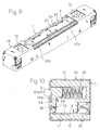
- a shield case 45 which is formed by applying a mechanical process such as a bending process on a metal sheet is placed outside the flat hollow housing 1 which laterally elongates, so that the housing 1 is covered by the shield case 45. More specifically, the shield case 45 is overlaid on the front face of the housing 1, the lower face of the bottom wall 13, and the upper face of the upper wall 14. In the embodiment, the shield case 45 corresponds to the grounding contact piece 41 formed by the conductor 4 in the embodiment which has been described with reference to Figs. 1 to 8.
- the shutter 5 is formed by the shutter body 56 which is configured by a resin molded product, and a metal sheet 57 which is attached to the front face of the shutter body 56.
- the metal sheet 57 is disposed over a substantially whole lateral length of the shutter body 56 which laterally elongates. Lateral end portions of the shutter body 56 are opposed to projection pieces 45a of the shield case 45 which are projected from lateral end portions of the insertion/extraction port 20 of the housing 1, respectively.
- the lateral end portions are formed as butting portions 57a.
- the shutter 5 which is elastically urged by the spring member 55 is at the closing position to close the insertion/extraction port 20 of the housing 1. Therefore, dust does not enter through the insertion/extraction port 20 into the housing 1, so that the terminals 3 and the grounding contact piece 41 which are accommodated in the housing 1 are prevented from being contaminated with dust. Since the butting portions 57a of the metal sheet 57 of the shutter 5 are in contact with the projection pieces 45a of the shield case 45 which serve as grounding contact pieces, the shutter 5 exhibits the electromagnetic wave shielding performance to block external electromagnetic waves. Therefore, the terminals which are accommodated in the housing, electronic devices which are electrically connected to the terminals, and the like are prevented from suffering electrostatic discharge damage.
- Figs. 11 to 20 show an embodiment of the plug type connector.
- the plug type connector A is formed into a laterally elongates rectangular shape in a plan view.
- the whole shape of the plug type connector A is defined by a hollow housing 6 which is formed into a flat box-like shape.
- a large number of grooves 62 are formed at regular intervals in the lateral direction, and contact pieces 7 are placed in the grooves 62, respectively.
- a wide attaching portion 71 is continuously integrated with the basal portion, and a support rod 72 is projected integrally from the attaching portion 71, so that the support rod 72 is in contact with the inner face of the housing 6 to be backed up.
- the front end 74 of the contact piece 7 is forward projected in front of a front face 63 of the housing 6, and the contact piece 7 is elastically deformable in the thickness direction of the plug type connector A indicated by the arrow T.
- a terminal 73 which is formed into a protruding arcuate shape is disposed in the front end 74.
- Forward protrusion portions 8 are projected integrally from the front face 63 of the housing 6.
- the protrusion portions 8 are disposed at regular intervals in the lateral direction on the front end face 63 of the housing 6.
- the front ends 74 of the contact pieces 7 and the terminals 73 are positioned between each pair of adjacent protrusion portions 8.
- Each of the terminals 73 is projected outside the outer profile line L (see Fig.
- the terminal 73 is projected to one side in the thickness direction T of the housing 6 with respect to the outer profile line L of the protrusion portion 8.
- an engagement piece 9 is attached to both ends in the lateral (width) direction W of the housing 6.
- the engagement piece 9 comprises an elastically deformable rod 91 which is projected in front of the front end face 63 of the housing 6, and an engagement claw 92 which is formed integrally with the rod 91.
- the specific shapes of the protrusion portions 8 and the engagement claws 92 will be described later.
- the housing 6 is formed into a flat rectangular box-like shape configured by the housing body 64 comprising the grooves 62, and a cover 65 which is coupled to the housing body 64 so as to cover the grooves 62.
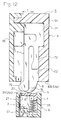
- the jack type connector B shown in Figs. 11 and 12 and the like and serving as a counter connector is identical with the connector which has been described with reference to Figs. 1 to 8. Therefore, the counter connector B is to be incorporated into a portable telephone serving as a mobile terminal device, and used for forming an IO port.
- the laterally elongated flat hollow housing 1 comprises the engagement face 25 which is to engage with the engagement claw 92 of the plug type connector A to prevent the plug type connector A from slipping off, in each of the lateral ends of the housing.
- the housing further comprises the recesses 21 (see Fig. 12) which are laterally arranged at regular intervals.
- the thin plate-like internal terminals 3 which are fitted into the recesses 21, respectively are arranged so as to be overlaid on the inner face of the housing 1 in the thickness direction (which coincides with the thickness direction T of the housing 6).
- the insertion/extraction port 20 is opened in a front end of the housing 1, and the shutter 5 is disposed in the insertion/extraction port 20.
- the shutter 5 is always elastically urged in the direction along which the insertion/extraction port 20 is closed, and, during the non-use period of the jack type connector B, located at the position where the shutter 5 closes the insertion/extraction port 20.
- the terminals 73 of the plug type connector A are inserted into the internal space S1 through the insertion/extraction port 20, the shutter 5 is pushed open by the protrusion portions 8.
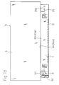
- the terminals 73 and the protrusion portions 8 of the plug type connector A are inserted into the internal space S1 of the jack type connector B through the insertion/extraction port 20 as indicated by the arrow Y in Fig. 14.
- the shutter 5 which closes the insertion/extraction port 20 is pushed open by the protrusion portions 8 and is retracted against the urging by the spring member 55, and the terminals 73 are then in contact with the internal terminals 3 of the jack type connector B, respectively.
- the degree of insertion of the terminals 73 with respect to the internal space S1 of the jack type connector B is restricted by butting of the front end face 63 of the housing 6 against the front face 24 of the housing 1. Therefore, the butting portion 63a and the receiving portion 24a which butt against each other to restrict the degree of insertion of the terminals 73 are formed by the front end face 63 of the housing 6, and the front face 24 of the housing 1 in which the edge portion of the insertion/extraction port 20 of the jack type connector B is formed, respectively.
- the plug type connector A is thicker than the jack type connector B.
- the whole of the receiving portion 24a which is the front face 24 of the housing 1 of the jack type connector B butts overlappingly against the butting portion 63a which is the front end face 63 of the housing 6 of the plug type connector A, as shown in Fig. 14.
- a prying force is applied in the thickness direction T of the plug type connector A, consequently, the plug type connector A is tilted as shown in Fig.
- the two positions i.e., the position of the outer edge 35a on the one side, and the outer edge 35b on the other side of the front face 24 of the housing 1 of the jack type connector B which butts against the front end face 63 of the housing 6 of the plug type connector A can be assumed as the position of the fulcrum of the prying and tilting of the plug type connector A.
- the shape of the protrusion portions 8 will be described in detail with reference to Fig. 17.
- each of the protrusion portions 8 is determined so that the protrusion portion 8 is positioned inside a virtual circle R1 which is centered at the one fulcrum P1 that is assumed by the position of the outer edge 35a on the one side of the housing 1 of the jack type connector B, and which has the radius elongating to an edge 20a of the insertion/extraction port 20, the edge being in a remoter side from the position of the one fulcrum, and inside a virtual circle R2 which is centered at the other fulcrum P2 that is assumed by the position of the other outer edge 35b, and which has the radius elongating to an edge 20b of the insertion/extraction port 20, the edge being in a remoter side from the position of the other fulcrum.
- the protrusion portions 8 forcibly press the peripheral wall faces of the internal space S1 of the jack type connector B, i.e., the inner wall face of the housing 1 and the shutter 5 to change their initial shapes.
- the protrusion portions 8 escape to the outside of the internal space S1 through the insertion/extraction port 20 without changing the initial shape of the peripheral wall faces of the internal space S1 of the jack type connector B, and the initial shape of the shutter 5. Even when the plug type connector A is pried, therefore, there arises no possibility that the protrusion portions 8 are damaged or the housing 1 of the jack type connector B is broken.
- the internal terminals 3 of the jack type connector B are arranged so as to be overlaid on the inner face of the housing 1 in the thickness direction of the jack type connector B, and hence the internal terminals 3 are placed outside the loci of movement in which the protrusion portions 8 escape to the outside of the internal space S1 through the insertion/extraction port 20. Therefore, there arises no possibility that the protrusion portions 8 interfere with the internal terminals 3 and the internal terminals 3 or the protrusion portions 8 are broken.
- the outer profile line L of each of the protrusion portions 8 has an ovaloid shape which elongates along the two virtual circles R1 and R2 in close proximity to the virtual circles R1 and R2.
- the outer profile line L of each of the protrusion portions 8 has an ovaloid shape which elongates along the virtual circles R1 and R2" means that the outer profile line L of the protrusion portion 8 has a tapered shape which elongates closer to the virtual circles R1 and R2 as approaching nearer to the tip end of the protrusion portion 8.
- the projection width C of the protrusion portions 8 from the front end face 63 of the housing 6 can be made as long as possible. Therefore, the projection length of the terminals 73 which are shown in Fig. 14 and the like, from the front end face 63 of the housing 6 can be made large correspondingly with the projection width C, and hence the contact range of the internal terminals 3 of the jack type connector B with respect to the terminals 73 can be prolonged.
- the engagement claw 92 is projected to the lateral side of the rod 91, and provided with inclined guide faces 94 around the engagement claw to be formed into a tapered shape.
- relief recesses 26 are formed in the jack type connector B.
- the inclined guide faces 94 have an inclination which allows the faces to slide over an edge 26a of corresponding one of the relief recesses 26 to override the edge 26a.
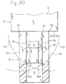
- Fig. 20 shows a virtual circle R3 which is centered at the one fulcrum P1, and which has the radius elongating to the edge 26a of the relief recess 26, the edge being in a remoter side from the position of the fulcrum on the one side, and a virtual circle R4 which is centered at the other fulcrum P2, and which has the radius elongating to the edge 26b of the relief recess 26, the edge being in a remoter side from the position of the fulcrum on the other side.
- the virtual circles are indicated by one-dot chain lines.
Landscapes
- Connector Housings Or Holding Contact Members (AREA)
- Coupling Device And Connection With Printed Circuit (AREA)
Applications Claiming Priority (4)
| Application Number | Priority Date | Filing Date | Title |
|---|---|---|---|
| JP2001213537 | 2001-07-13 | ||
| JP2001213537A JP4576073B2 (ja) | 2001-07-13 | 2001-07-13 | シャッター付き多極コネクタ |
| JP2001219700 | 2001-07-19 | ||
| JP2001219700A JP3749840B2 (ja) | 2001-07-19 | 2001-07-19 | コネクタ |
Publications (3)
| Publication Number | Publication Date |
|---|---|
| EP1276176A2 true EP1276176A2 (de) | 2003-01-15 |
| EP1276176A3 EP1276176A3 (de) | 2003-12-10 |
| EP1276176B1 EP1276176B1 (de) | 2012-05-09 |
Family
ID=26618687
Family Applications (1)
| Application Number | Title | Priority Date | Filing Date |
|---|---|---|---|
| EP02014866A Expired - Lifetime EP1276176B1 (de) | 2001-07-13 | 2002-07-04 | Verbinder mit Schutzkappe |
Country Status (6)
| Country | Link |
|---|---|
| US (1) | US7300292B2 (de) |
| EP (1) | EP1276176B1 (de) |
| KR (1) | KR100516750B1 (de) |
| CN (1) | CN100444476C (de) |
| CA (1) | CA2392501C (de) |
| TW (1) | TW571464B (de) |
Cited By (1)
| Publication number | Priority date | Publication date | Assignee | Title |
|---|---|---|---|---|
| GB2398185A (en) * | 2003-01-07 | 2004-08-11 | Vtech Communications Ltd | An electrostatic discharge device with movable shield |
Families Citing this family (9)
| Publication number | Priority date | Publication date | Assignee | Title |
|---|---|---|---|---|
| JP4181895B2 (ja) * | 2003-02-25 | 2008-11-19 | 日本圧着端子製造株式会社 | リセプタクル |
| JP4491393B2 (ja) * | 2005-09-27 | 2010-06-30 | 富士通株式会社 | 携帯端末装置 |
| JP2010073353A (ja) * | 2008-09-16 | 2010-04-02 | Mitsumi Electric Co Ltd | インタフェースコネクタ及びプラグ |
| US7883276B2 (en) * | 2008-10-14 | 2011-02-08 | Sonosite, Inc. | Optical transmission coupling |
| JP5080692B2 (ja) * | 2009-09-01 | 2012-11-21 | オリンパスメディカルシステムズ株式会社 | 電気コネクタ及び内視鏡 |
| JP5366759B2 (ja) * | 2009-10-28 | 2013-12-11 | 日本航空電子工業株式会社 | コネクタ |
| JP5660148B2 (ja) * | 2013-02-22 | 2015-01-28 | Tdk株式会社 | 端子台及びそれを含む電子機器 |
| CN110737055B (zh) * | 2018-07-18 | 2021-04-20 | 武汉福地科技有限公司 | 一种用于数据传输的高速光模块 |
| CN112433564B (zh) * | 2020-12-07 | 2025-02-18 | 重庆交通职业学院 | 一种计算机监控装置固定安装机构 |
Family Cites Families (18)
| Publication number | Priority date | Publication date | Assignee | Title |
|---|---|---|---|---|
| FR1373438A (fr) * | 1962-10-30 | 1964-09-25 | Bbc Brown Boveri & Cie | Accouplement électrique formé de deux têtes d'accouplement |
| US4146291A (en) * | 1977-08-03 | 1979-03-27 | Msi Data Corporation | Antistatic electrical connector housing |
| DE3604764A1 (de) * | 1986-02-14 | 1987-08-20 | Dynamit Nobel Ag | Elektrische steckverbindung |
| US4780793A (en) * | 1986-06-03 | 1988-10-25 | Daiichi Denshi Kogyo Kabushiki Kaisha | IC card and connector therefor |
| JP2601800B2 (ja) | 1986-06-16 | 1997-04-16 | 株式会社東芝 | 画像形成装置 |
| KR900004629B1 (ko) * | 1986-06-20 | 1990-06-30 | 미쓰비시전기 주식회사 | 카세트 테이프 플레이어 등에서의 개폐문 도통기구 |
| KR930009394B1 (ko) * | 1988-02-12 | 1993-10-02 | 세이꼬 엡슨 가부시끼가이샤 | 커넥터의 전하를 제거하기 위한 구조체 |
| JPH02222087A (ja) * | 1989-02-23 | 1990-09-04 | Toshiba Corp | 記録媒体接続装置 |
| JPH0650270A (ja) | 1991-04-15 | 1994-02-22 | Shuichi Kitamura | 非接触回転機械の羽根と回転中心体とを有するローターの構築方法 |
| US5167516A (en) * | 1991-08-21 | 1992-12-01 | Foxconn International, Inc. | Connection with floating shield |
| JP2669750B2 (ja) | 1992-07-30 | 1997-10-29 | 松下電子工業株式会社 | 固体撮像装置の駆動方法 |
| JPH0620570U (ja) * | 1992-08-26 | 1994-03-18 | 株式会社イナックス | フロート弁鎖の接続構造 |
| JPH0650270U (ja) * | 1992-12-11 | 1994-07-08 | エスエムケイ株式会社 | コネクタ及びプラグ |
| JP2601800Y2 (ja) * | 1993-04-05 | 1999-12-06 | ホシデン株式会社 | ジャック型コネクタ |
| JP2999364B2 (ja) * | 1994-04-08 | 2000-01-17 | ヒロセ電機株式会社 | 電気コネクタ |
| JPH0878096A (ja) * | 1994-08-31 | 1996-03-22 | Hosiden Corp | 多極コネクタ |
| JP4129318B2 (ja) * | 1998-07-22 | 2008-08-06 | 東洋技研株式会社 | 安全プラグ装置 |
| US6179479B1 (en) * | 1999-07-09 | 2001-01-30 | Veam S.R.L. | Fiber optic connector with self-closing shutter |
-
2002
- 2002-07-03 US US10/187,972 patent/US7300292B2/en not_active Expired - Fee Related
- 2002-07-04 CA CA002392501A patent/CA2392501C/en not_active Expired - Fee Related
- 2002-07-04 EP EP02014866A patent/EP1276176B1/de not_active Expired - Lifetime
- 2002-07-04 TW TW091114834A patent/TW571464B/zh not_active IP Right Cessation
- 2002-07-12 CN CNB021406723A patent/CN100444476C/zh not_active Expired - Fee Related
- 2002-07-13 KR KR10-2002-0040944A patent/KR100516750B1/ko not_active Expired - Fee Related
Non-Patent Citations (1)
| Title |
|---|
| None |
Cited By (1)
| Publication number | Priority date | Publication date | Assignee | Title |
|---|---|---|---|---|
| GB2398185A (en) * | 2003-01-07 | 2004-08-11 | Vtech Communications Ltd | An electrostatic discharge device with movable shield |
Also Published As
| Publication number | Publication date |
|---|---|
| CA2392501C (en) | 2007-12-18 |
| US20030013333A1 (en) | 2003-01-16 |
| CA2392501A1 (en) | 2003-01-13 |
| EP1276176B1 (de) | 2012-05-09 |
| KR100516750B1 (ko) | 2005-09-22 |
| HK1050274A1 (zh) | 2003-06-13 |
| CN1398026A (zh) | 2003-02-19 |
| CN100444476C (zh) | 2008-12-17 |
| KR20030007172A (ko) | 2003-01-23 |
| TW571464B (en) | 2004-01-11 |
| EP1276176A3 (de) | 2003-12-10 |
| US7300292B2 (en) | 2007-11-27 |
Similar Documents
| Publication | Publication Date | Title |
|---|---|---|
| US6364699B1 (en) | Cable connector assembly device with improved latching means | |
| US8172579B2 (en) | Electrical connector having dust-proof shutter driven by magnetic force | |
| EP1801936A1 (de) | Elektrischer Verbinder | |
| EP1276176B1 (de) | Verbinder mit Schutzkappe | |
| US6845210B2 (en) | Optical connector with a shutter | |
| US11189956B2 (en) | Liquid-tight movable connector | |
| CN112385095A (zh) | 屏蔽连接器及外导体端子 | |
| US6988908B2 (en) | Cable end connector assembly with a pressing device | |
| EP0898331A1 (de) | Elektrischer Steckverbinder | |
| KR20000017090A (ko) | 커넥터의 하우징 및 그것에 의해 제조된 커넥터 | |
| US6231368B1 (en) | Half-fitting prevention connector | |
| JP2003086287A (ja) | 汚れ防止された差込み接続装置のためのソケット及び差込み接続装置 | |
| US7207814B2 (en) | Electrical card connector | |
| GB2261776A (en) | Shuttered electrical connector | |
| US10770837B2 (en) | Connector having a slider holder | |
| US6948953B2 (en) | Connector connecting construction and a connector connecting method | |
| EP1315247A2 (de) | Elektrischer Steckverbinder mit Abdeck- und Ausrichtmitteln | |
| US6000972A (en) | Structure for fixing terminal to connector housing | |
| CN109690878B (zh) | 连接器 | |
| JP2999364B2 (ja) | 電気コネクタ | |
| US6383030B1 (en) | Electrical connector | |
| US6062875A (en) | Electrical connector with minimized socket opening | |
| JP4576073B2 (ja) | シャッター付き多極コネクタ | |
| HK1050274B (en) | Jack type connector with a shutter, and plug type connector | |
| JP4045151B2 (ja) | プラグ型コネクタ |
Legal Events
| Date | Code | Title | Description |
|---|---|---|---|
| PUAI | Public reference made under article 153(3) epc to a published international application that has entered the european phase |
Free format text: ORIGINAL CODE: 0009012 |
|
| AK | Designated contracting states |
Kind code of ref document: A2 Designated state(s): AT BE BG CH CY CZ DE DK EE ES FI FR GB GR IE IT LI LU MC NL PT SE SK TR |
|
| AX | Request for extension of the european patent |
Free format text: AL;LT;LV;MK;RO;SI |
|
| PUAL | Search report despatched |
Free format text: ORIGINAL CODE: 0009013 |
|
| AK | Designated contracting states |
Kind code of ref document: A3 Designated state(s): AT BE BG CH CY CZ DE DK EE ES FI FR GB GR IE IT LI LU MC NL PT SE SK TR |
|
| AX | Request for extension of the european patent |
Extension state: AL LT LV MK RO SI |
|
| 17P | Request for examination filed |
Effective date: 20040528 |
|
| RIN1 | Information on inventor provided before grant (corrected) |
Inventor name: NAGATA, TAKAYUKI |
|
| AKX | Designation fees paid |
Designated state(s): DE FI FR GB IT NL SE |
|
| 17Q | First examination report despatched |
Effective date: 20100806 |
|
| GRAP | Despatch of communication of intention to grant a patent |
Free format text: ORIGINAL CODE: EPIDOSNIGR1 |
|
| RIC1 | Information provided on ipc code assigned before grant |
Ipc: H01R 13/648 20060101ALI20111214BHEP Ipc: H01R 13/453 20060101AFI20111214BHEP |
|
| GRAS | Grant fee paid |
Free format text: ORIGINAL CODE: EPIDOSNIGR3 |
|
| GRAA | (expected) grant |
Free format text: ORIGINAL CODE: 0009210 |
|
| AK | Designated contracting states |
Kind code of ref document: B1 Designated state(s): DE FI FR GB IT NL SE |
|
| REG | Reference to a national code |
Ref country code: GB Ref legal event code: FG4D |
|
| REG | Reference to a national code |
Ref country code: DE Ref legal event code: R096 Ref document number: 60242847 Country of ref document: DE Effective date: 20120712 |
|
| REG | Reference to a national code |
Ref country code: NL Ref legal event code: T3 |
|
| REG | Reference to a national code |
Ref country code: SE Ref legal event code: TRGR |
|
| PGFP | Annual fee paid to national office [announced via postgrant information from national office to epo] |
Ref country code: SE Payment date: 20120731 Year of fee payment: 11 Ref country code: GB Payment date: 20120731 Year of fee payment: 11 Ref country code: FI Payment date: 20120724 Year of fee payment: 11 |
|
| PGFP | Annual fee paid to national office [announced via postgrant information from national office to epo] |
Ref country code: FR Payment date: 20120814 Year of fee payment: 11 Ref country code: DE Payment date: 20120727 Year of fee payment: 11 |
|
| PGFP | Annual fee paid to national office [announced via postgrant information from national office to epo] |
Ref country code: NL Payment date: 20120727 Year of fee payment: 11 |
|
| PGFP | Annual fee paid to national office [announced via postgrant information from national office to epo] |
Ref country code: IT Payment date: 20120725 Year of fee payment: 11 |
|
| PLBE | No opposition filed within time limit |
Free format text: ORIGINAL CODE: 0009261 |
|
| STAA | Information on the status of an ep patent application or granted ep patent |
Free format text: STATUS: NO OPPOSITION FILED WITHIN TIME LIMIT |
|
| 26N | No opposition filed |
Effective date: 20130212 |
|
| REG | Reference to a national code |
Ref country code: DE Ref legal event code: R097 Ref document number: 60242847 Country of ref document: DE Effective date: 20130212 |
|
| REG | Reference to a national code |
Ref country code: NL Ref legal event code: V1 Effective date: 20140201 |
|
| REG | Reference to a national code |
Ref country code: SE Ref legal event code: EUG |
|
| GBPC | Gb: european patent ceased through non-payment of renewal fee |
Effective date: 20130704 |
|
| REG | Reference to a national code |
Ref country code: DE Ref legal event code: R119 Ref document number: 60242847 Country of ref document: DE Effective date: 20140201 |
|
| REG | Reference to a national code |
Ref country code: FR Ref legal event code: ST Effective date: 20140331 |
|
| PG25 | Lapsed in a contracting state [announced via postgrant information from national office to epo] |
Ref country code: NL Free format text: LAPSE BECAUSE OF NON-PAYMENT OF DUE FEES Effective date: 20140201 Ref country code: SE Free format text: LAPSE BECAUSE OF NON-PAYMENT OF DUE FEES Effective date: 20130705 Ref country code: FI Free format text: LAPSE BECAUSE OF NON-PAYMENT OF DUE FEES Effective date: 20130704 Ref country code: GB Free format text: LAPSE BECAUSE OF NON-PAYMENT OF DUE FEES Effective date: 20130704 Ref country code: DE Free format text: LAPSE BECAUSE OF NON-PAYMENT OF DUE FEES Effective date: 20140201 |
|
| PG25 | Lapsed in a contracting state [announced via postgrant information from national office to epo] |
Ref country code: IT Free format text: LAPSE BECAUSE OF NON-PAYMENT OF DUE FEES Effective date: 20130704 Ref country code: FR Free format text: LAPSE BECAUSE OF NON-PAYMENT OF DUE FEES Effective date: 20130731 |