EP1276202B1 - Unterbrechungsfreie Stromversorgung und Verfahren zum Ausschalten eines Wechselstromschalters für eine Unterbrechungsfreie Stromversorgung - Google Patents
Unterbrechungsfreie Stromversorgung und Verfahren zum Ausschalten eines Wechselstromschalters für eine Unterbrechungsfreie Stromversorgung Download PDFInfo
- Publication number
- EP1276202B1 EP1276202B1 EP02254419A EP02254419A EP1276202B1 EP 1276202 B1 EP1276202 B1 EP 1276202B1 EP 02254419 A EP02254419 A EP 02254419A EP 02254419 A EP02254419 A EP 02254419A EP 1276202 B1 EP1276202 B1 EP 1276202B1
- Authority
- EP
- European Patent Office
- Prior art keywords
- sinusoidal voltage
- voltage
- power supply
- synchronous
- power
- Prior art date
- Legal status (The legal status is an assumption and is not a legal conclusion. Google has not performed a legal analysis and makes no representation as to the accuracy of the status listed.)
- Expired - Lifetime
Links
Images



Classifications
-
- H—ELECTRICITY
- H02—GENERATION; CONVERSION OR DISTRIBUTION OF ELECTRIC POWER
- H02J—ELECTRIC POWER NETWORKS; CIRCUIT ARRANGEMENTS OR SYSTEMS FOR SUPPLYING OR DISTRIBUTING ELECTRIC POWER; SYSTEMS FOR STORING ELECTRIC ENERGY
- H02J9/00—Circuit arrangements for emergency or stand-by power supply, e.g. for emergency lighting
- H02J9/04—Circuit arrangements for emergency or stand-by power supply, e.g. for emergency lighting in which the distribution system is disconnected from the normal source and connected to a standby source
- H02J9/06—Circuit arrangements for emergency or stand-by power supply, e.g. for emergency lighting in which the distribution system is disconnected from the normal source and connected to a standby source with automatic change-over, e.g. UPS systems
- H02J9/062—Circuit arrangements for emergency or stand-by power supply, e.g. for emergency lighting in which the distribution system is disconnected from the normal source and connected to a standby source with automatic change-over, e.g. UPS systems for AC powered loads
Definitions
- the present invention relates to an uninterruptible power supply which connects a load to utility power supply through an AC switch.
- AC switches used in conventional uninterruptible power supplies employ switching element with a self turn-off function or thyristors that are turned off by a forced turn-off circuit.
- AC switch Another type of AC switch is also used which does not use a turn-off circuit and is naturally turned off as a current flowing in the thyristor falls below a holding current.
- the use of the AC switch incorporating only such thyristors can reduce the cost of the uninterruptible power supply.
- a period occurs without fail during which two AC powers are parallelly connected to and fed to a load, delaying the turn-off of the AC switch, as indicated in Japanese Patent Laid-Open Nos. 5-30683 , 5-176461 and 5-292686 .
- U.S. patent US 4 641 042 discloses an uninterruptable power supply with all features of the preamble of claim 1.
- a conventional thyristor-based AC switch 1 for each phase has antiparallelly connected thyristors SCR1 and SCR2 disposed between a utility or commercial power supply 3 and a power converter 5 for each phase.
- the power converter 5 has a function of converting an AC power into a DC power and vice versa, and is connected to a DC power supply 7 on a DC side thereof.
- the electric power from the utility power supply 3 is fed through the AC switch 1 to a load 9, and the output from the power converter 5 is supplied directly to the load 9.
- an ON signal is applied to the power converter 5 and an OFF signal is supplied to the AC switch 1.
- the AC switch 1 uses thyristors without the self turn-off function, the current flowing through the AC switch 1 does not fall immediately to zero and thus there is a period when the utility power supply 3 and the power converter 5 are connected parallelly to the load 9. During this period, depending on the voltage relation between the utility power supply 3 and the power converter 5, an uncontrollable cross current flows between the power converter 5 and the utility power supply 3, rendering the voltage applied to the load 9 abnormal.
- the inexpensive AC switch 1 comprising only the thyristors SCR1 and SCR2 that do not use a forced turn-off circuit, therefore, has a problem that it cannot make an instantaneous switchover of the feeding path.
- Still another object of the present invention is to provide an uninterruptible power supply capable of turning off an AC switch made up of thyristors without providing a separate, forced turn-off circuit.
- Yet another object of the present invention is to provide an AC switch turn-off method for an uninterruptible power supply capable of turning off an AC switch made up of thyristors without providing a separate, forced turn-off circuit.
- an uninterruptible power supply comprising:
- control command generation means (13) outputs the voltage control command.
- control command generation means (13) outputs the voltage control command at all times, and wherein, when the power converter is inoperable, the AC switch (1) is controlled to conduct.
- control command generation means (13) outputs the voltage control command to the power converter (5) when the utility power supply (3) fails or, when the utility power supply is normal, outputs a current control command to the power converter to cause the power converter to operate as an active filter.
- the uninterruptible power supply further comprises:
- the sinusoidal voltage selection means (11c) comprises:
- the uninterruptible power supply comprises:
- phase shift type sinusoidal voltage generation means (19b) generates the synchronous sinusoidal voltage Vref1, the leading sinusoidal voltage Vref4 equal in amplitude to and leading the synchronous sinusoidal voltage Vref1 by a phase difference command value DELTA phi, and the lagging sinusoidal voltage Vref5 equal in amplitude to and lagging the synchronous sinusoidal voltage Vref1 by the phase difference command value DELTA phi.
- phase shift type sinusoidal voltage selection means (19c) selects the leading sinusoidal voltage Vref4, the lagging sinusoidal voltage Vref5 or the synchronous sinusoidal voltage Vref1 and outputs the selected voltage as the reference sinusoidal voltage to the control command generation means (13), wherein the phase shift type sinusoidal voltage selection means selects the leading sinusoidal voltage Vref4 after the current has changed from the negative polarity to the positive polarity until the synchronous sinusoidal voltage Vref1 reaches a positive peak value, selects the lagging sinusoidal voltage Vref5 after the synchronous sinusoidal voltage has reached the positive peak value until the current changes from the positive polarity to the negative polarity, selects the leading sinusoidal voltage Vref4 after the current has changed from the positive polarity to the negative polarity until the synchronous sinusoidal voltage reaches a negative peak value, selects the lagging sinusoidal voltage Vref5 after the synchronous sinusoidal voltage has reached the negative peak value until the current changes from the negative polarity to the positive polarity
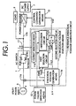
- Fig. 1 is a circuit block diagram schematically showing one example configuration in which the present invention is applied to an uninterruptible power supply of normally utility power and active filter type.
- Fig. 1 shows only a single phase component, i.e., connections and a control system for one phase.
- an AC switch 1 a voltage control type power converter 5 and a DC power supply 7 are basically the same as the conventional ones.
- the voltage control type power converter 5 is installed between the AC switch 1 and the DC power supply 7.
- the power converter 5 When the utility power is normal, the power converter 5 performs a rectifier operation in which it converts an AC power from a three-phase AC utility power supply 3 into a DC power and charges the DC power supply 7 with the rectified DC power and also an active filter operation that generates currents to compensate for a harmonic current and a reactive current flowing into the load 9. At other times, the power converter 5 performs mainly an inverter operation in which it converts a DC power from the DC power supply 7 into an AC power and supplies the inverted AC power to the load 9. As shown in Fig. 8A, the load 9 is supplied from the utility power supply 3 through the first feeding path R1 during the rectifier operation and, during the inverter operation, from the power converter 5 through the second feeding path R2.
- the AC switch 1 installed between the utility power supply 3 and the power converter 5 corresponds to one phase and comprises two antiparallelly connected thyristors SCR1 and SCR2.
- the load 9 is supplied with an AC power from the utility power supply 3 through the AC switch 1.
- the AC switch 1 is opened to stop supplying the AC power from the utility power supply 3 to the load 9.
- a reference sinusoidal voltage generation circuit 11 When a power failure detection means 12 detects the presence or absence of a power failure, a reference sinusoidal voltage generation circuit 11 outputs a reference sine wave signal for controlling the power converter 5 to a control command generation means 13. Based on the reference sinusoidal voltage, the control command generation means 13 outputs to the power converter 5 a voltage control command for having the power converter 5 perform the inverter operation and a current control command for having the power converter 5 perform the rectifier operation and the active filter operation.
- the power failure detection means 12 may, for example, have a known configuration which determines the occurrence of a power failure when a voltage detection circuit detects that a voltage of one phase is lower than a predetermined voltage.
- the control command generation means 13 actually receives signals representing information necessary for the control of the voltage and current on the AC side of the power converter 5 and the DC voltage on the DC side.
- the configurations of the power converter 5 and the control command generation means 13 are disclosed in Japanese Patent Laid-Open Nos. 8-51735 , 9-56087 and 10-14251 and also detailed in Japanese Patent Application 2000-288480 ( US Serial No. 09/956,185 , EP Application No. 01250328.0 ), a previous application by this applicant.
- the reference sinusoidal voltage generation circuit 11 comprises a current detection means 11a for detecting a current flowing through the AC switch 1, a sinusoidal voltage generation means 11b for generating a sine wave voltage to be output as the reference sinusoidal voltage to the control command generation means 13, and a sinusoidal voltage selection means 11c for selecting a sine wave voltage to be output as the reference sinusoidal voltage to the control command generation means 13.
- the current detection means 11a based on an analog current value detected by a current transformer CT, outputs a current detection signal necessary for the control.
- the sinusoidal voltage generation means 11b generates a synchronous sinusoidal voltage Vref1, a high synchronous sinusoidal voltage Vref2, and a low synchronous sinusoidal voltage Vref3.
- the synchronous sinusoidal voltage Vref1 is synchronized with the utility power supply 3 and, when used as the reference sinusoidal voltage, causes the output voltage of the power converter 5 to be almost equal to the voltage of the utility power supply 3.
- the high synchronous sinusoidal voltage Vref2 is in phase with the synchronous sinusoidal voltage Vref1 and larger in amplitude than the synchronous sinusoidal voltage Vref1.
- the low synchronous sinusoidal voltage Vref3 is in phase with the synchronous sinusoidal voltage Vref1 and smaller in amplitude than the synchronous sinusoidal voltage Vref1.
- the output voltage of the power converter 5 appears on a line 17b of Fig. 1. If the synchronous sinusoidal voltage Vref1 is used as the reference sinusoidal voltage Vref, an AC output equal in phase and amplitude to the AC voltage of the utility power supply 3 is produced on the line 17b.
- the sinusoidal voltage selection means 11c selects the synchronous sinusoidal voltage Vref1 when the power failure detection means 12 does not detect a power outage or a power failure.
- the sinusoidal voltage selection means 11c selects the high synchronous sinusoidal voltage Vref2 when the output of the current detection means 11a has a positive polarity, the low synchronous sinusoidal voltage Vref3 when the output of the current detection means 11a has a negative polarity, and the synchronous sinusoidal voltage Vref1 when the output of the current detection means 11a is zero, before outputting the selected sinusoidal voltage as the reference sinusoidal voltage to the control command generation means 13.
- the reference sinusoidal voltage generation circuit 11 selects the high synchronous sinusoidal voltage Vref2 or low synchronous sinusoidal voltage Vref3, the conducting thyristor SCR1 or SCR2 of the AC switch 1 is applied a reverse bias and turned off. After the current-carrying thyristor has been turned off, when the reference sinusoidal voltage generation circuit 11 selects the synchronous sinusoidal voltage Vref1 as the reference sinusoidal voltage, the AC switch 1 remains turned off and the power converter 5 starts the inverter operation. When the power failure detection means 12 does not detect the power outage, the reference sinusoidal voltage generation circuit 11 outputs the synchronous sinusoidal voltage Vref1. Using the synchronous sinusoidal voltage Vref1 as its input, the control command generation means 13 performs an active filter operation. This operation is detailed in the previous application and thus its explanation is omitted here.
- the sinusoidal voltage generation means 11b in this example generates the high synchronous sinusoidal voltage Vref2 by adding a voltage difference command value ⁇ V to the synchronous sinusoidal voltage Vref1 synchronized with the utility power supply 3, and the low synchronous sinusoidal voltage Vref3 by subtracting the voltage difference command value ⁇ V from the synchronous sinusoidal voltage Vref1.
- the voltage difference command value ⁇ V is preset based on thyristor characteristics to produce a reverse bias voltage that can reliably effect a turn-off.
- Fig. 2 shows waveforms of the synchronous sinusoidal voltage Vref1, the high synchronous sinusoidal voltage Vref2 and the low synchronous sinusoidal voltage Vref3 and a waveform of an AC current I.
- Vref Vref ⁇ 1 + ⁇ V ⁇ sign I ⁇ S
- Vref Vref ⁇ 2 when I ⁇ 0
- sign I - 1
- sign I 0
- Vref Vref ⁇ 1
- symbol I is assumed to be a current value as detected by the current detection means 11a.
- the reference sinusoidal voltage Vref is the synchronous sinusoidal voltage Vref1, making the voltage of the line 17b almost equal to the voltage of the utility power supply 3.
- the conducting thyristor of the AC switch 1 remains turned on.
- S is assumed to be S-1.
- equation (2) or (3) holds for the reference sinusoidal voltage Vref of equation (1).
- the reference sinusoidal voltage Vref switches from the synchronous sinusoidal voltage Vref1 to the synchronous sinusoidal voltage indicated by a thick line in the graph of Fig. 2.
- the reference sinusoidal voltage Vref in equation (1) returns to the synchronous sinusoidal voltage Vref1.
- the current detection means 11a detects a positive current
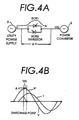
- the current is flowing through the antiparallelly connected thyristor SCR1, as shown in Fig. 4A.
- the line 17b is applied a voltage Vrb, which is ⁇ V higher than the voltage V of the utility power supply 3, and the thyristor SCR1 is impressed with a reverse bias of ⁇ V, causing the current I to drop to zero.
- Fig. 4B shows how the voltage and current waveforms change over time in this situation. As shown in Fig.
- the sinusoidal voltage selection means 11c selects the low synchronous sinusoidal voltage Vref3 as the reference sinusoidal voltage and a reverse bias is applied to the thyristor SCR2, thus interrupting the current flowing through the thyristor SCR2.
- the sinusoidal voltage generation means 11b in the reference sinusoidal voltage generation circuit 11 shown in Fig. 1 produces the synchronous sinusoidal voltage Vref1, the high synchronous sinusoidal voltage Vref2 and the low synchronous sinusoidal voltage Vref3 by using the voltage difference command value AV.
- the sinusoidal voltage generation means 11b may use a PLL circuit for instance.
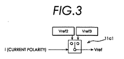
- a first selection circuit 11c1 in the sinusoidal voltage selection means 11c selects the high synchronous sinusoidal voltage Vref2 when the output of the current detection means 11a is positive and the low synchronous sinusoidal voltage Vref3 when the output of the current detection means 11a is negative.
- Fig. 3 shows a detailed configuration of the first selection circuit 11c1.
- a first decision circuit 11c2 decides that an output voltage of the first selection circuit 11c1 is required as the reference sinusoidal voltage.
- the second selection circuit 11c3 selects the output voltage of the first selection circuit 11c1.
- the second selection circuit 11c3 selects the synchronous sinusoidal voltage Vref1.
- Fig. 5 is a block diagram showing another embodiment (phase difference method) of the present invention. Parts identical with those of Fig. 1 are assigned like reference numerals.
- a phase shift type reference sinusoidal voltage generation circuit 19 is used as the reference sinusoidal voltage generation circuit.
- the phase shift type reference sinusoidal voltage generation circuit 19 comprises a current detection means 19a for detecting a current flowing through the AC switch 1, a phase shift type sinusoidal voltage generation means 19b, and a phase shift type sinusoidal voltage selection means 19c.
- the phase shift type sinusoidal voltage generation means 19b generates the synchronous sinusoidal voltage Vref1 used in the first embodiment, a leading sinusoidal voltage Vref4 which is equal in amplitude to and leading in phase the synchronous sinusoidal voltage Vref1, and a lagging sinusoidal voltage Vref5 which is equal in amplitude to and lagging in phase the synchronous sinusoidal voltage Vref1.
- the phase shift type sinusoidal voltage selection means 19c selects the synchronous sinusoidal voltage Vref1 when the power failure detection means 12 does not detect a power outage.
- the phase shift type sinusoidal voltage selection means 19c selects the leading sinusoidal voltage Vref4 or the lagging sinusoidal voltage Vref5 whichever is larger in amplitude than the synchronous sinusoidal voltage while the current I is positive. While the current I is negative, the phase shift type sinusoidal voltage selection means 19c selects whichever of the leading and lagging sinusoidal voltages Vref4 and Vref5 is smaller in amplitude than the synchronous sinusoidal voltage. When the output of the current detection means is zero, the phase shift type sinusoidal voltage selection means 19c selects the synchronous sinusoidal voltage Vref1. The selected sinusoidal voltage is then output as the reference sinusoidal voltage to the control command generation means 13.
- the phase shift type sinusoidal voltage generation means 19b generates a cosine wave voltage Vcos which leads the synchronous sinusoidal voltage Vref1 by 90 degrees. This cosine wave voltage is used by the phase shift type sinusoidal voltage selection means 19c described later.
- the operation of the uninterruptible power supply shown in Fig. 5 will be explained with reference to waveforms of Fig. 6.
- Fig. 6 illustrates waveforms of the synchronous sinusoidal voltage Vref1, the leading sinusoidal voltage Vref4 and the lagging sinusoidal voltage Vref5 and also a waveform of the current I.
- the phase shift type reference sinusoidal voltage generation circuit 19 outputs the leading sinusoidal voltage Vref4 as the reference sinusoidal voltage.
- the phase shift type reference sinusoidal voltage generation circuit 19 outputs the lagging sinusoidal voltage Vref5 as the reference sinusoidal voltage to the load line 17b.
- a transition of the reference sinusoidal voltage that depends on the product of the current and the cosine wave voltage Vcos is shown by a thick line.
- Comparison in amplitude between the thick line voltage and the synchronous sinusoidal voltage Vref1 synchronized with the utility power supply 3 shows that the voltage applied to the AC switch 1 is reverse-biased with respect to the current. This arrangement causes a reverse bias to be applied to the current-carrying thyristor thus interrupting the current in that thyristor.
- ⁇ ⁇ t where ⁇ is an angular frequency of AC power and t is time.
- the common amplitudes of the voltages are omitted here.
- the synchronous sinusoidal voltage Vref1 matches the voltage on the line 17b in amplitude and phase.
- ⁇ represents a phase shift angle.
- the synchronous sinusoidal voltage Vref1 lies between the leading sinusoidal voltage Vref4 and the lagging sinusoidal voltage Vref5 in most area.
- Vref4 or Vref5 is larger than the synchronous sinusoidal voltage Vref1 and whichever is smaller Vref4 or Vref5, is smaller than the synchronous sinusoidal voltage Vref1. Therefore, in an area where I ⁇ Vref ⁇ 4 - Vref ⁇ 5 > 0
- Vref4 is selected as the voltage of the line 17b.
- Vref4 is selected as the voltage of the line 17b.
- Equation (10) The left-hand member of equation (8) can be rewritten as I ⁇ Vref ⁇ 4 - Vref ⁇ 5 ⁇ 2 I ⁇ sin ⁇ ⁇ cos ⁇ ⁇ Vcos ⁇ I
- equation (10) the following is assumed: Vcos ⁇ cos ⁇
- sin ( ⁇ ) is omitted in transforming the right-hand member of equation (9) into the right-hand member of equation (10) is that, from the definition of the phase difference command value ⁇ , sin ( ⁇ ) > 0 and therefore sin ( ⁇ ) becomes unnecessary in the following explanation regarding the signs of the right-hand members of equation (9) and equation (10).
- the synchronous sinusoidal voltage Vref1 is larger than the leading sinusoidal voltage Vref4 and the lagging sinusoidal voltage Vref5.
- the period of the phase shift angle ⁇ during the phase angle ⁇ is the percentage of the time that the thyristor cannot be turned off.
- the phase shift angle ⁇ is sufficiently small compared with ⁇ , the time during which the thyristor cannot be turned off can be kept sufficiently short. Therefore, the effect of the delayed thyristor turn-off can be kept to the minimum.
- the phase shift type sinusoidal voltage selection means 19c outputs the synchronous sinusoidal voltage Vref1.
- phase shift type reference sinusoidal voltage generation circuit 19 The configuration of the phase shift type reference sinusoidal voltage generation circuit 19 that realizes the above-described functions will be explained by referring to Fig. 5.
- the phase shift type sinusoidal voltage generation means 19b generates and outputs the synchronous sinusoidal voltage Vref1, the leading sinusoidal voltage Vref4, the lagging sinusoidal voltage Vref5 and the cosine wave voltage Vcos. More specifically, the phase shift type sinusoidal voltage generation means 19b may be realized with a PLL circuit.
- a first selection circuit 19c1 that forms a part of the phase shift type sinusoidal voltage selection means 19c selects the leading sinusoidal voltage Vref4 when the product of the current output from the current detection means 19a and the cosine wave voltage Vcos is positive and the lagging sinusoidal voltage Vref5 when the product of the current output from current detection means and Vcos is negative.
- a first decision circuit 19c2 decides that the output voltage of the first selection circuit 1901 is required for the reference sinusoidal voltage.
- a second selection circuit 19c3 selects the output voltage of the first selection circuit 19c1. When the signal is not received, the second selection circuit 19c3 selects the synchronous sinusoidal voltage Vref1.
- Fig. 7A shows an example logic circuit of the first selection circuit 19c1 of Fig. 5.
- Input signals to the first selection circuit 19c1 of Fig. 5 are Vcos, Vref4 and Vref5. Generated from these signals are input signals BV and BVcos to the logic circuit of Fig. 7A, and a same polarity signal X.
- These input signals BV, BVcos go High when the synchronous sinusoidal voltage Vref1 and the cosine wave voltage Vcos are positive, respectively.
- the input signals BV and BVcos are also pulsed logic signals that go Low when the synchronous sinusoidal voltage Vref1 and the cosine wave voltage Vcos are negative, respectively.
- Fig. 7A The same polarity signal X goes High when the signs of the synchronous sinusoidal voltage Vref1 and the current I flowing through the thyristor are the same and goes Low when they are opposite.
- Fig. 7B shows another example of a logic circuit of the first selection circuit 19c1 of Fig. 5.
- the first selection circuit 19c1 receives pulsed logic signals BVcos and BI at its inputs which go High when the cosine wave voltage Vcos and the current I flowing through the thyristor are positive, respectively, and which go Low when they are negative.
- the block diagram of Fig. 5 does not show these logical input signals, they can be derived from the input signals I and Vcos shown in the figure.
- the logic diagram of Fig. 7B may be expressed by the following logic equation.
- Y BI ⁇ BVcos + NBI ⁇ NBVcos
- equation (15) when I > 0 and Vcos > 0, the first term goes High; and when I ⁇ 0 and Vcos ⁇ 0, the second term goes High. Hence, in equation (15) Y becomes High when I ⁇ Vcos > 0. This matches the condition of the first decision circuit described earlier.
- the output of the decision circuit of Fig. 7B is High, the leading sinusoidal voltage Vref4 is selected; and when the output is Low, the lagging sinusoidal voltage Vref5 is selected.
- Fig. 8B shows a configuration of an uninterruptible power supply to which the present invention can be applied.
- the utility power supply 3 normally feeds the load 9 through the first feeding path R1. If the utility power supply 3 should fail, a DC power from a storage battery 21 is converted by the power converter 5 into an AC power before being fed to the load 9 through the second feeding path R2. At this time the power converter 5 operates as an inverter. In this uninterruptible power supply, too, during a power failure the first feeding path R1 is switched over to the second feeding path R2, so that the AC switch 1 must be turned off quickly.
- Fig. 8C shows a configuration of another uninterruptible power supply to which the present invention can be applied.
- an AC power from the utility power supply 3 is converted by a power converter 23 into a DC power which is used to charge a storage battery 21 and the DC output of the power converter 23 is converted by the power converter 5 into an AC power which is then fed to the load 9 during a normal condition.
- This equipment is called a normally inverter feeding method. With this equipment, in the event of a failure of the second feeding path R2, the AC switch turns on feeding the load through the first feeding path R1, When, after the recovery of the second feeding path R2, the first feeding path R1 is switched over to the second feeding path R2, the AC switch 1 is turned off.
- the reference sinusoidal voltage generation circuit in the event that the utility power supply fails, since the reference sinusoidal voltage generation circuit generates a reference sinusoidal voltage that sets an output voltage of the power converter to such a level as can apply a reverse bias to a conducting one of the thyristors making up the AC switch, the AC switch can be turned off quickly without having to provide a special, forced thyristor turn-off circuit.
- the invention as defined in claim 1 offers an advantage that during the process of turning off the AC switch, there exists no period of time when the utility power supply and the power converter are paralleled, thus preventing a cross current from flowing between the utility power supply and the power converter.
Landscapes
- Business, Economics & Management (AREA)
- Emergency Management (AREA)
- Engineering & Computer Science (AREA)
- Power Engineering (AREA)
- Stand-By Power Supply Arrangements (AREA)
Claims (9)
- Unterbrechungsfreie Stromversorgung, die umfasst:einen ersten Zuführweg (R1) zum Zuführen eines Wechselstroms zu einer Last (9) von einer Netzstromversorgung (3) über einen Wechselstromschalter (1), der aus einem Paar antiparallel verbundener Thyristoren besteht;und einen zweiten Zuführweg (R2), der einen Spannungssteuer-Stromrichter (5) enthält, wobei der Stromrichter eine Gleichstromversorgung (7) als seine Quelle nutzt und einen Invertiervorgang des Umwandelns eines Gleichstroms in einen Wechselstrom sowie des Zuführens des umgewandelten Wechselstroms zu der Last durchführt;eine Steuerbefehl-Erzeugungseinrichtung;eine Bezugs-Sinusspannungs-Erzeugungsschaltung (11), die eine Bezugs-Sinusspannung produziert;eine Stromerfassungseinrichtung (11a), die einen Strom erfasst, der durch den Wechselstromschalter (1) fließt, dadurch gekennzeichnet, dass sie des Weiteren umfasst:die Steuerbefehl-Einrichtung (13), die auf Basis der Bezugs-Sinusspannung an den Stromrichter (5) einen Spannungs-Steuerbefehl ausgibt, um den Stromrichter zu veranlassen, den Invertiervorgang durchzuführen, wobei, wenn der Spannungs-Steuerbefehl von der Steuerbefehl-Erzeugungseinrichtung ausgegeben wird, der Wechselstromschalter (1) geöffnet wird und die Zufuhr des Wechselstroms zu der Last (9) von dem ersten Zuführweg (R1) auf den zweiten Zuführweg (R2) umgeschaltet wird;wobei die Bezugs-Sinusspannungs-Erzeugungsschaltung (11) enthält:eine Sinusspannungs-Erzeugungseinrichtung (11 b), die eine Synchron-Sinusspannung Vref1, eine Hoch-Synchron-Sinusspannung Vref2 und eine Nieder-Synchron-Sinusspannung Vref3 erzeugt, wobei die Synchron-Sinusspannung Vref1 mit der Netzstromversorgung (3) synchronisiert ist und wenn sie als die Bezugs-Sinusspannung verwendet wird, bewirkt, dass eine Ausgangsspannung des Stromrichters (5) nahe zu einer Spannung der Netzstromversorgung gleich wird, die Hoch-Synchron-Sinusspannung Vref2 die gleiche Phase hat wie die Synchron-Sinusspannung Vref1 und ihre Amplitude um einen Spannungsunterschied-Befehlswert ΔV höher ist als die der Synchron-Sinusspannung Vref1, und die Nieder-Synchron-Sinusspannung Vref3 die gleiche Phase hat wie die Synchron-Sinusspannung Vref1 und ihre Amplitude um den Spannungsdifferenz-Befehlswert ΔV niedriger ist als die der Synchron-Sinusspannung Vref1;eine Sinusspannungs-Auswähleinrichtung (11c), die die Synchron-Sinusspannung Vref1, die Hoch-Synchron-Sinusspannung Vref2 oder die Nieder-Synchron-Sinusspannung Vref3 auswählt und die ausgewählte Spannung als die Bezugs-Sinusspannung an die Steuerbefehl-Erzeugungseinrichtung (13) ausgibt,wobei, wenn der Spannungs-Steuerbefehl nicht ausgegeben wird, die Sinusspannungs-Auswähleinrichtung (11c) die Synchron-Sinusspannung Vref1 auswählt, und wobei, wenn der Spannungs-Steuerbefehl ausgegeben wird, die Sinusspannungs-Auswähleinrichtung die Hoch-Synchron-Sinusspannung Vref2 auswählt, wenn ein Ausgang der Stromerfassungseinrichtung (11a) eine positive Polarität hat, die Nieder-Synchron-Sinusspannung Vref3 auswählt, wenn der Ausgang der Stromerfassungseinrichtung eine negative Polarität hat, und die Synchron-Sinusspannung Vref1 auswählt, wenn der Ausgang der Stromerfassungseinrichtung Null ist.
- Unterbrechungsfreie Stromversorgung nach Anspruch 1, wobei, wenn die Netzstromversorgung (3) ausfällt, die Steuerbefehl-Erzeugungseinrichtung (13) den Spannungs-Steuerbefehl ausgibt.
- Unterbrechungsfreie Stromversorgung nach Anspruch 1, wobei, wenn der Stromrichter (5) in Funktion ist, die Steuerbefehl-Erzeugungseinrichtung (13) ständig den Spannungs-Steuerbefehl ausgibt, und, wenn der Stromrichter nicht in Funktion ist, der Wechselstromschalter (1) so gesteuert wird, dass er leitet.
- Unterbrechungsfreie Stromversorgung nach Anspruch 1, wobei die Steuerbefehl-Erzeugungseinrichtung (13) den Spannungs-Steuerbefehl an den Stromrichter (5) ausgibt, wenn die Netzstromversorgung (3) ausfällt, oder, wenn die Netzstromversorgung normal ist, einen Strom-Steuerbefehl an den Stromrichter ausgibt, um zu bewirken, dass der Stromrichter als ein aktives Filter arbeitet.
- Unterbrechungsfreie Stromversorgung nach Anspruch 1, die umfasst:eine Stromausfall-Erfassungseinrichtung (12), die einen Stromausfall in einer Netzstromversorgung (3) erfasst;wobei der Spannungssteuer-Stromrichter (5) zwischen dem Wechselstromschalter (1) und der Gleichstromversorgung (7) angeordnet ist, wenn die Netzstromversorgung (3) genutzt werden kann, der Stromrichter einen Gleichrichtvorgang des Umwandelns des Wechselstroms von der Netzstromversorgung in einen Gleichstrom und des Ladens der Gleichstromversorgung mit dem Gleichstrom durchführt und einen aktiven Filtervorgang des Kompensierens eines Oberwellenstroms sowie eines Blindstroms, die in die Last (9) fließen, durchführt, und wobei ansonsten der Stromrichter die Gleichstromversorgung als seine Quelle nutzt und hauptsächlich einen Invertiervorgang des Umwandelns eines Gleichstroms in einen Wechselstrom sowie des Zuführens des umgewandelten Wechselstroms zu der Last durchführt;wobei die Steuerbefehl-Erzeugungseinrichtung (13) auf Basis der Bezugs-Sinusspannung an den Stromrichter (5) den Spannungs-Steuerbefehl ausgibt, um den Stromrichter zu veranlassen, den Invertiervorgang durchzuführen, und einen Strom-Steuerbefehl, um den Stromrichter zu veranlassen, den Gleichrichtvorgang und den aktiven Filtervorgang durchzuführen; undwobei die Sinusspannungs-Auswähleinrichtung (11c) die Synchron-Sinusspannung Vref1, die Hoch-Synchron-Sinusspannung Vref2 oder die Nieder-Synchron-Sinusspannung Vref3 auswählt und die ausgewählte Spannung als die Bezugs-Sinusspannung an die Steuerbefehl-Erzeugungseinrichtung (13) ausgibt,wobei, wenn die Stromausfall-Erfassungseinrichtung (12) keinen Stromausfall erfasst und der Spannungs-Steuerbefehl nicht ausgegeben wird, die Sinusspannungs-Auswähleinrichtung die Synchron-Sinusspannung Vref1 auswählt, und wobei, wenn die Stromausfall-Erfassungseinrichtung einen Stromausfall erfasst und der Spannungs-Steuerbefehl ausgegeben wird, die Sinusspannungs-Auswähleinrichtung die Hoch-Synchron-Sinusspannung Vref2 auswählt, wenn ein Ausgang der Stromerfassungseinrichtung (11a) eine positive Polarität hat, die Nieder-Synchron-Sinusspannung Vref3 auswählt, wenn der Ausgang der Stromerfassungseinrichtung eine negative Polarität hat, und die Synchron-Sinusspannung Vref1 auswählt, wenn der Ausgang der Stromerfassungseinrichtung Null ist.
- Unterbrechungsfreie Stromversorgung nach Anspruch 5,wobei die Sinusspannungs-Auswähleinrichtung (11c) umfasst:eine erste Auswählschaltung (11c1), die die Hoch-Synchron-Sinusspannung Vref2 auswählt, wenn der Ausgang der Stromerfassungseinrichtung eine positive Polarität hat, und die Nieder-Synchron-Sinusspannung Vref3, wenn der Ausgang der Stromerfassungseinrichtung eine negative Polarität hat;eine erste Entscheidungsschaltung (11c2), die entscheidet, dass eine Ausgangsspannung der ersten Auswählschaltung als die Bezugs-Sinusspannung erforderlich ist, wenn die Stromausfall-Erfassungseinrichtung einen Stromausfall erfasst und die Stromerfassungseinrichtung erfasst, dass der Strom nicht Null ist; undeine zweite Auswählschaltung (11 c3), die die Ausgangsspannung der ersten Auswählschaltung (11c1) auswählt, wenn die erste Entscheidungsschaltung (11c2) entscheidet, dass die Ausgangsspannung der ersten Auswählschaltung erforderlich ist, und ansonsten die Synchron-Sinusspannung Vref1 auswählt.
- Unterbrechungsfreie Stromversorgung, die umfasst:eine Stromausfall-Erfassungseinrichtung (12), die einen Stromausfall in einer Netzstromversorgung (3) erfasst;eine Stromerfassungseinrichtung (19a), die einen Strom erfasst, der durch den Wechselstromschalter fließt;einen Wechselstromschalter (11), der ein Paar antiparallel verbundener Thyristoren aufweist, wobei der Wechselstromschalter so eingerichtet ist, dass er einen Wechselstrom von der Netzstromversorgung zu der Last (9) zuführt, wenn die Netzstromversorgung normal ist, und der Wechselstromschalter geöffnet wird, wenn die Netzstromversorgung ausfällt;eine Gleichstromversorgung (7); undeine Steuerbefehl-Erzeugungseinrichtung; dadurch gekennzeichnet, dass sie des Weiteren umfasst:einen Spannungssteuer-Stromrichter (5), der zwischen dem Wechselstromschalter und der Gleichstromversorgung angeordnet ist, wobei, wenn die Netzstromversorgung normal ist, der Stromrichter einen Gleichrichtvorgang des Umwandelns des Wechselstroms von der Netzstromversorgung in einen Gleichstrom und des Ladens der Gleichstromversorgung mit dem Gleichstrom durchführt und einen aktiven Filtervorgang des Kompensierens eines Oberwellenstroms sowie eines Blindstroms, die in die Last fließen, durchführt, und wobei ansonsten der Stromrichter die Gleichstromversorgung als seine Quelle nutzt und hauptsächlich einen Invertiervorgang des Umwandelns eines Gleichstroms in einen Wechselstrom sowie des Zuführens des umgewandelten Wechselstroms zu der Last durchführt, dadurch gekennzeichnet, dass die unterbrechungsfreie Stromversorgung des Weiteren umfasst:eine Bezugs-Sinusspannungs-Erzeugungsschaltung (19) vom Phasenschiebetyp zum Erzeugen einer Bezugs-Sinusspannung;die Steuerbefehl-Erzeugungseinrichtung (13), die auf Basis der Bezugs-Sinusspannung an den Stromrichter einen Spannungs-Steuerbefehl ausgibt, um den Stromrichter zu veranlassen, den Invertiervorgang durchzuführen, und einen Strom-Steuerbefehl, um den Stromrichter zu veranlassen, den Gleichrichtvorgang und den aktiven Filtervorgang durchzuführen;wobei die Bezugs-Sinusspannungs-Erzeugungsschaltung (19) vom Phasenschiebetyp umfasst:eine Bezugs-Sinusspannungs-Erzeugungseinrichtung (19b) vom Phasenschiebetyp, die eine Synchron-Sinusspannung Vref1, eine Vorlauf-Sinusspannung Vref4 und eine Nachlauf-Sinusspannung Vref5 erzeugt, wobei die Synchron-Sinusspannung Vref1 mit der Netzstromversorgung synchronisiert ist, und wenn sie als die Bezugs-Sinusspannung verwendet wird, bewirkt, dass eine Ausgangsspannung des Stromrichters bezüglich der Amplitude einer Spannung der Netzstromversorgung nahezu gleich wird, die Vorlauf-Sinusspannung Vref4 der Synchron-Sinusspannung bezüglich der Amplitude gleich ist und Phasenvorlauf ihr gegenüber aufweist, und die Nachlauf-Sinusspannung Vref5 der Synchron-Sinusspannung Vref1 bezüglich der Amplitude gleich ist und ihr gegenüber Phasennachlauf aufweist;eine Sinusspannungs-Auswähleinrichtung (19c) vom Phasenschiebetyp, die die Synchron-Sinusspannung Vref1, die Vorlauf-Sinusspannung Vref4 oder die Nachlauf-Sinusspannung Vref5 auswählt und die ausgewählte Spannung als die Bezugs-Sinusspannung an die Steuerbefehl-Erzeugungseinrichtung (13) ausgibt,wobei, wenn die Stromausfall-Erfassungseinrichtung (12) keinen Stromausfall erfasst und der Spannungs-Steuerbefehl nicht ausgegeben wird, die Sinusspannungs-Auswähleinrichtung (19c) vom Phasenschiebetyp die Synchron-Sinusspannung Vref1 auswählt, und, wobei, wenn die Stromausfall-Erfassungseinrichtung einen Stromausfall erfasst und der Spannungs-Steuerbefehl ausgegeben wird, die Sinusspannungs-Auswähleinrichtung vom Phasenschiebetyp die Vorlauf-Sinusspannung Vref4 oder die Nachlauf-Sinusspannung Vref5 in Abhängigkeit davon, welche größer ist als die Synchron-Sinusspannung Vref1, auswählt, wenn ein Ausgang der Stromerfassungseinrichtung eine positive Polarität hat, die Vorlauf-Sinusspannung Vref4 oder die Nachlauf-Sinusspannung Vref5 in Abhängigkeit davon auswählt, welche kleiner ist als die Synchron-Sinusspannung, wenn der Ausgang der Stromerfassungseinrichtung eine negative Polarität hat, und die Synchron-Sinusspannung Vref1 auswählt, wenn der Ausgang der Stromerfassungseinrichtung (19a) Null ist.
- Unterbrechungsfreie Stromversorgung nach Anspruch 7, wobei die Sinusspannungs-Erzeugungseinrichtung (19b) vom Phasenschiebetyp die Synchron-Sinusspannung Vref1, die Vorlauf-Sinusspannung Vref4, die der Synchron-Sinusspannung Vref1 bezüglich der Amplitude gleich ist und ihr gegenüber Vorlauf um einen Phasendifferenz-Befehlswert DELTA phi aufweist, und die Nachlauf-Sinusspannung Vref5 erzeugt, die der Synchron-Sinusspannung Vref1 bezüglich der Amplitude gleich ist und ihr gegenüber Nachlauf um den Phasendifferenz-Befehlswert DELTA phi aufweist.
- Unterbrechungsfreie Stromversorgung nach Anspruch 7, wobei die Sinusspannungs-Auswählspannung (19c) vom Phasenschiebetyp die Vorlauf-Sinusspannung Vref4, die Nachlauf-Sinusspannung Vref5 oder die Synchron-Sinusspannung Vref1 auswählt und die ausgewählte Spannung als die Bezugs-Sinusspannung an der Steuerbefehl-Erzeugungseinrichtung (13) ausgibt, wobei die Sinusspannungs-Auswähleinrichtung vom Phasenschiebetyp die Vorlauf-Sinusspannung Vref4 ausgibt, nachdem der Strom von der negativen Polarität zu der positiven Polarität gewechselt hat, bis die Synchron-Sinusspannung Vref1 einen positiven Spitzenwert erreicht, die Nachlauf-Spannung Vref 5 auswählt, nachdem die Synchron-Sinusspannung den positiven Spitzenwert erreicht hat, bis der Strom von der positiven Polarität zu der negativen Polarität wechselt, die Vorlauf-Sinusspannung Vref4 auswählt, nachdem der Strom von der positiven Polarität zu der negativen Polarität gewechselt hat, bis die Synchron-Sinusspannung einen negativen Spitzenwert erreicht, die Nachlauf-Sinusspannung Vref5 auswählt, nachdem die Synchron-Sinusspannung den negativen Spitzenwert erreicht hat, bis der Strom von der negativen Polarität zu der positiven Polarität wechselt, und die Synchron-Sinusspannung Vref1 auswählt, wenn die Stromerfassungseinrichtung (19a) erfasst, dass der Strom Null ist.
Applications Claiming Priority (2)
| Application Number | Priority Date | Filing Date | Title |
|---|---|---|---|
| JP2001193357 | 2001-06-26 | ||
| JP2001193357 | 2001-06-26 |
Publications (3)
| Publication Number | Publication Date |
|---|---|
| EP1276202A2 EP1276202A2 (de) | 2003-01-15 |
| EP1276202A3 EP1276202A3 (de) | 2005-01-05 |
| EP1276202B1 true EP1276202B1 (de) | 2008-01-09 |
Family
ID=19031662
Family Applications (1)
| Application Number | Title | Priority Date | Filing Date |
|---|---|---|---|
| EP02254419A Expired - Lifetime EP1276202B1 (de) | 2001-06-26 | 2002-06-25 | Unterbrechungsfreie Stromversorgung und Verfahren zum Ausschalten eines Wechselstromschalters für eine Unterbrechungsfreie Stromversorgung |
Country Status (3)
| Country | Link |
|---|---|
| US (1) | US6556459B2 (de) |
| EP (1) | EP1276202B1 (de) |
| DE (1) | DE60224477T2 (de) |
Cited By (1)
| Publication number | Priority date | Publication date | Assignee | Title |
|---|---|---|---|---|
| EP3291411A1 (de) | 2016-09-01 | 2018-03-07 | Maschinenfabrik Reinhausen GmbH | Verfahren zum steuern einer unterbrechungsfreien stromversorgung und anlage für eine unterbrechungsfreie stromversorgung |
Families Citing this family (22)
| Publication number | Priority date | Publication date | Assignee | Title |
|---|---|---|---|---|
| US7786616B2 (en) * | 2003-02-07 | 2010-08-31 | Cummins Power Generation Inc. | Generator with DC boost and split bus bidirectional DC-to-DC converter for uninterruptible power supply system or for enhanced load pickup |
| TWI279961B (en) * | 2003-03-31 | 2007-04-21 | Fuji Electric Co Ltd | Uninterruptible power supply system |
| JP2004312849A (ja) * | 2003-04-04 | 2004-11-04 | Sanyo Denki Co Ltd | 蓄電池劣化判定回路付無停電給電装置 |
| GR1007463B (el) * | 2009-10-23 | 2011-11-18 | Αλεξανδρος Γεωργιου Κατσουλης | Μεθοδος και συσκευη αναγνωρισης διακοπης ρευματος σε διακοπτομενο ηλεκτρολογικο σημειο εναλλασσομενου δικτυου |
| US8791597B2 (en) | 2010-03-12 | 2014-07-29 | Liebert Corporation | Uninterruptible power supply with a dual gain voltage regulator controlling an inverter output voltage based on active and reactive components of current |
| US8310104B2 (en) * | 2010-03-14 | 2012-11-13 | Gengenbach Gary A | Substantially bumpless transfer grid synchronization |
| JP5879728B2 (ja) * | 2010-09-17 | 2016-03-08 | 東芝ライテック株式会社 | 電源装置、照明装置および電源システム |
| KR101276582B1 (ko) * | 2011-12-27 | 2013-06-19 | 전자부품연구원 | 전원 공급 회로를 가지는 인버터 장치 |
| US9160202B2 (en) | 2012-01-31 | 2015-10-13 | General Electric Company | Control system for uninterruptible power supplies |
| US9236768B2 (en) | 2012-01-31 | 2016-01-12 | Lorenzo Giuntini | Systems, methods, and devices for control of parallel uninterruptible power supplies |
| US8823338B2 (en) | 2012-01-31 | 2014-09-02 | Green Charge Networks Llc | Universal single-stage power converter |
| US8897041B2 (en) * | 2012-01-31 | 2014-11-25 | Green Charge Networks Llc | Universal power conversion methods and systems |
| EP2720338B1 (de) * | 2012-10-10 | 2021-06-09 | FIMER S.p.A. | Verfahren und Vorrichtung zum Erkennen des Inselbetriebs eines verteilten Stromgenerators |
| KR101590698B1 (ko) * | 2014-03-31 | 2016-02-01 | 엘지전자 주식회사 | 전원 판단 장치 |
| US10284007B2 (en) | 2014-10-23 | 2019-05-07 | Abb Schweiz Ag | Protection methods and switches in uninterruptible power supply systems |
| US10042007B2 (en) | 2015-02-04 | 2018-08-07 | Liebert Corporation | Method for detecting a failing rectifier or rectifier source |
| JP6538874B2 (ja) * | 2015-12-01 | 2019-07-03 | 東芝三菱電機産業システム株式会社 | 無停電電源装置 |
| WO2019021416A1 (ja) * | 2017-07-27 | 2019-01-31 | 東芝三菱電機産業システム株式会社 | 交流スイッチならびにそれを備える無停電電源装置および瞬低補償装置 |
| US10148124B1 (en) * | 2018-01-05 | 2018-12-04 | Channel Well Technology Co., Ltd. | Uninterrupted power bank capable of supplying high DC voltage during interruption of main supply and providing AC voltage as normal supply of the main supply |
| CN110048626B (zh) * | 2019-05-22 | 2020-08-28 | 阳光电源股份有限公司 | 逆变器交流合闸共模冲击电流抑制方法及其应用装置 |
| CN113285691B (zh) * | 2020-02-19 | 2024-03-08 | 瑞昱半导体股份有限公司 | 滤波器、滤波方法以及滤波系统 |
| TWI795978B (zh) * | 2021-11-03 | 2023-03-11 | 台達電子工業股份有限公司 | 具有路徑強迫關斷功能之不斷電裝置及其路徑強迫關斷方法 |
Family Cites Families (12)
| Publication number | Priority date | Publication date | Assignee | Title |
|---|---|---|---|---|
| DE2904786C2 (de) * | 1979-02-08 | 1981-02-19 | Siemens Ag, 1000 Berlin Und 8000 Muenchen | Verfahren zur Regelung von Wechselrichtern im Parallelbetrieb und Schaltungsanordnungen zur Durchführung des Verfahrens |
| JPS58112423A (ja) * | 1981-12-26 | 1983-07-04 | 株式会社東芝 | 電力変換設備の制御方式 |
| JPS60249832A (ja) * | 1984-05-25 | 1985-12-10 | 株式会社東芝 | インバ−タの保護方法 |
| JP2695941B2 (ja) * | 1989-09-22 | 1998-01-14 | 株式会社東芝 | 無停電電源装置 |
| DE69011312T2 (de) * | 1990-01-29 | 1994-12-01 | Toshiba Kawasaki Kk | Wechselrichtersteuerungsgerät. |
| US5111374A (en) * | 1990-06-22 | 1992-05-05 | The University Of Tennessee Research Corp. | High frequency quasi-resonant DC voltage notching scheme of a PWM voltage fed inverter for AC motor drives |
| US5111376A (en) * | 1990-11-01 | 1992-05-05 | Sundstrand Corporation | Voltage balancing circuit |
| JP2949929B2 (ja) | 1991-07-23 | 1999-09-20 | 富士電機株式会社 | 無停電電源装置の電源切替え方法 |
| JPH05176461A (ja) | 1991-12-20 | 1993-07-13 | Yuasa Corp | 交流電源装置 |
| JPH05292686A (ja) | 1992-04-10 | 1993-11-05 | Toyo Electric Mfg Co Ltd | 交流スイッチ装置 |
| US6160722A (en) * | 1999-08-13 | 2000-12-12 | Powerware Corporation | Uninterruptible power supplies with dual-sourcing capability and methods of operation thereof |
| US6768223B2 (en) * | 2000-06-01 | 2004-07-27 | Liebert Corporation | Apparatus and method for rapid fault detection and transfer in a utility-interactive uninterruptible power supply |
-
2002
- 2002-06-25 EP EP02254419A patent/EP1276202B1/de not_active Expired - Lifetime
- 2002-06-25 DE DE60224477T patent/DE60224477T2/de not_active Expired - Lifetime
- 2002-06-26 US US10/180,692 patent/US6556459B2/en not_active Expired - Lifetime
Cited By (3)
| Publication number | Priority date | Publication date | Assignee | Title |
|---|---|---|---|---|
| EP3291411A1 (de) | 2016-09-01 | 2018-03-07 | Maschinenfabrik Reinhausen GmbH | Verfahren zum steuern einer unterbrechungsfreien stromversorgung und anlage für eine unterbrechungsfreie stromversorgung |
| WO2018041742A1 (de) | 2016-09-01 | 2018-03-08 | Maschinenfabrik Reinhausen Gmbh | Verfahren zum steuern einer unterbrechungsfreien stromversorgung und anlage für eine unterbrechungsfreie stromversorgung |
| US10797515B2 (en) | 2016-09-01 | 2020-10-06 | Maschinenfabrik Reinhausen Gmbh | Method for controlling an uninterruptible power supply and system for an uninterruptible power supply |
Also Published As
| Publication number | Publication date |
|---|---|
| EP1276202A3 (de) | 2005-01-05 |
| US6556459B2 (en) | 2003-04-29 |
| DE60224477D1 (de) | 2008-02-21 |
| EP1276202A2 (de) | 2003-01-15 |
| US20020195879A1 (en) | 2002-12-26 |
| DE60224477T2 (de) | 2009-02-26 |
Similar Documents
| Publication | Publication Date | Title |
|---|---|---|
| EP1276202B1 (de) | Unterbrechungsfreie Stromversorgung und Verfahren zum Ausschalten eines Wechselstromschalters für eine Unterbrechungsfreie Stromversorgung | |
| EP2827487B1 (de) | Stromrichter | |
| US6144191A (en) | Voltage regulator | |
| US11394295B2 (en) | Power supply apparatus | |
| EP1450476B1 (de) | Stromrichterschaltung | |
| US20030090155A1 (en) | Electric power system interconnection device | |
| JP3771200B2 (ja) | 無停電電源装置及び無停電電源装置の交流スイッチ遮断方法 | |
| US6545481B1 (en) | Power interruption detection | |
| JP3469918B2 (ja) | 無停電電源装置 | |
| JPH09247952A (ja) | 無停電運転方法及び電源装置 | |
| EP2824818B1 (de) | Stromwandler | |
| JP4374605B2 (ja) | Pwmサイクロコンバータ | |
| JP3550573B2 (ja) | 電力変換装置 | |
| JP2009254102A (ja) | 無停電電源装置 | |
| JP3826722B2 (ja) | 無停電工事用電源装置 | |
| JP4893113B2 (ja) | 整流回路の制御装置 | |
| KR102797634B1 (ko) | 위상 동기 제어 회로 및 그것을 이용한 전력 변환 장치 | |
| WO2018185813A1 (ja) | 電力変換装置 | |
| JPS59117470A (ja) | 電力制御回路 | |
| JPH0488847A (ja) | 交流無停電電源装置 | |
| JP7387913B1 (ja) | 無停電電源装置 | |
| JPH04109835A (ja) | 交流無停電電源装置 | |
| JP3766788B2 (ja) | 無停電電源装置 | |
| JP2641162B2 (ja) | サイリスタ短絡検出装置 | |
| JPS63206165A (ja) | 無停電電源装置 |
Legal Events
| Date | Code | Title | Description |
|---|---|---|---|
| PUAI | Public reference made under article 153(3) epc to a published international application that has entered the european phase |
Free format text: ORIGINAL CODE: 0009012 |
|
| AK | Designated contracting states |
Kind code of ref document: A2 Designated state(s): AT BE CH CY DE DK ES FI FR GB GR IE IT LI LU MC NL PT SE TR |
|
| AX | Request for extension of the european patent |
Free format text: AL;LT;LV;MK;RO;SI |
|
| PUAL | Search report despatched |
Free format text: ORIGINAL CODE: 0009013 |
|
| AK | Designated contracting states |
Kind code of ref document: A3 Designated state(s): AT BE CH CY DE DK ES FI FR GB GR IE IT LI LU MC NL PT SE TR |
|
| AX | Request for extension of the european patent |
Extension state: AL LT LV MK RO SI |
|
| 17P | Request for examination filed |
Effective date: 20050303 |
|
| 17Q | First examination report despatched |
Effective date: 20050412 |
|
| AKX | Designation fees paid |
Designated state(s): DE FR GB IT SE |
|
| GRAP | Despatch of communication of intention to grant a patent |
Free format text: ORIGINAL CODE: EPIDOSNIGR1 |
|
| GRAS | Grant fee paid |
Free format text: ORIGINAL CODE: EPIDOSNIGR3 |
|
| GRAA | (expected) grant |
Free format text: ORIGINAL CODE: 0009210 |
|
| AK | Designated contracting states |
Kind code of ref document: B1 Designated state(s): DE FR GB IT SE |
|
| REG | Reference to a national code |
Ref country code: GB Ref legal event code: FG4D |
|
| REF | Corresponds to: |
Ref document number: 60224477 Country of ref document: DE Date of ref document: 20080221 Kind code of ref document: P |
|
| PG25 | Lapsed in a contracting state [announced via postgrant information from national office to epo] |
Ref country code: SE Free format text: LAPSE BECAUSE OF FAILURE TO SUBMIT A TRANSLATION OF THE DESCRIPTION OR TO PAY THE FEE WITHIN THE PRESCRIBED TIME-LIMIT Effective date: 20080409 |
|
| PLBE | No opposition filed within time limit |
Free format text: ORIGINAL CODE: 0009261 |
|
| STAA | Information on the status of an ep patent application or granted ep patent |
Free format text: STATUS: NO OPPOSITION FILED WITHIN TIME LIMIT |
|
| 26N | No opposition filed |
Effective date: 20081010 |
|
| GBPC | Gb: european patent ceased through non-payment of renewal fee |
Effective date: 20080625 |
|
| PG25 | Lapsed in a contracting state [announced via postgrant information from national office to epo] |
Ref country code: GB Free format text: LAPSE BECAUSE OF NON-PAYMENT OF DUE FEES Effective date: 20080625 |
|
| PGFP | Annual fee paid to national office [announced via postgrant information from national office to epo] |
Ref country code: IT Payment date: 20120627 Year of fee payment: 11 |
|
| PG25 | Lapsed in a contracting state [announced via postgrant information from national office to epo] |
Ref country code: IT Free format text: LAPSE BECAUSE OF NON-PAYMENT OF DUE FEES Effective date: 20130625 |
|
| PGFP | Annual fee paid to national office [announced via postgrant information from national office to epo] |
Ref country code: DE Payment date: 20140619 Year of fee payment: 13 |
|
| PGFP | Annual fee paid to national office [announced via postgrant information from national office to epo] |
Ref country code: FR Payment date: 20140619 Year of fee payment: 13 |
|
| REG | Reference to a national code |
Ref country code: DE Ref legal event code: R119 Ref document number: 60224477 Country of ref document: DE |
|
| REG | Reference to a national code |
Ref country code: FR Ref legal event code: ST Effective date: 20160229 |
|
| PG25 | Lapsed in a contracting state [announced via postgrant information from national office to epo] |
Ref country code: DE Free format text: LAPSE BECAUSE OF NON-PAYMENT OF DUE FEES Effective date: 20160101 |
|
| PG25 | Lapsed in a contracting state [announced via postgrant information from national office to epo] |
Ref country code: FR Free format text: LAPSE BECAUSE OF NON-PAYMENT OF DUE FEES Effective date: 20150630 |