EP1276220A2 - Alimentation d'énergie avec condensateur pyroélectrique - Google Patents
Alimentation d'énergie avec condensateur pyroélectrique Download PDFInfo
- Publication number
- EP1276220A2 EP1276220A2 EP02253483A EP02253483A EP1276220A2 EP 1276220 A2 EP1276220 A2 EP 1276220A2 EP 02253483 A EP02253483 A EP 02253483A EP 02253483 A EP02253483 A EP 02253483A EP 1276220 A2 EP1276220 A2 EP 1276220A2
- Authority
- EP
- European Patent Office
- Prior art keywords
- capacitor
- power supply
- voltage
- pyroelectric
- pulses
- Prior art date
- Legal status (The legal status is an assumption and is not a legal conclusion. Google has not performed a legal analysis and makes no representation as to the accuracy of the status listed.)
- Granted
Links
- 239000003990 capacitor Substances 0.000 title claims abstract description 61
- 230000001105 regulatory effect Effects 0.000 claims abstract description 13
- 238000001816 cooling Methods 0.000 claims description 13
- 238000011084 recovery Methods 0.000 claims description 13
- 239000000758 substrate Substances 0.000 claims description 8
- 239000010409 thin film Substances 0.000 claims description 8
- 238000000034 method Methods 0.000 claims description 7
- 230000004888 barrier function Effects 0.000 claims 2
- 239000000463 material Substances 0.000 description 36
- 238000010438 heat treatment Methods 0.000 description 14
- 239000013078 crystal Substances 0.000 description 12
- 230000010287 polarization Effects 0.000 description 10
- 230000001419 dependent effect Effects 0.000 description 4
- 238000013461 design Methods 0.000 description 4
- 238000006073 displacement reaction Methods 0.000 description 4
- 230000003247 decreasing effect Effects 0.000 description 3
- 238000010586 diagram Methods 0.000 description 3
- 229910052751 metal Inorganic materials 0.000 description 3
- 239000002184 metal Substances 0.000 description 3
- XUIMIQQOPSSXEZ-UHFFFAOYSA-N Silicon Chemical compound [Si] XUIMIQQOPSSXEZ-UHFFFAOYSA-N 0.000 description 2
- 230000008878 coupling Effects 0.000 description 2
- 238000010168 coupling process Methods 0.000 description 2
- 238000005859 coupling reaction Methods 0.000 description 2
- 238000010348 incorporation Methods 0.000 description 2
- 230000005855 radiation Effects 0.000 description 2
- 239000004065 semiconductor Substances 0.000 description 2
- 229910052710 silicon Inorganic materials 0.000 description 2
- 239000010703 silicon Substances 0.000 description 2
- 229910007322 Li2SO2 Inorganic materials 0.000 description 1
- 229910003327 LiNbO3 Inorganic materials 0.000 description 1
- 229910012463 LiTaO3 Inorganic materials 0.000 description 1
- 239000004020 conductor Substances 0.000 description 1
- 238000001514 detection method Methods 0.000 description 1
- 238000007429 general method Methods 0.000 description 1
- XLYOFNOQVPJJNP-ZSJDYOACSA-N heavy water Substances [2H]O[2H] XLYOFNOQVPJJNP-ZSJDYOACSA-N 0.000 description 1
- 230000010354 integration Effects 0.000 description 1
- 238000004519 manufacturing process Methods 0.000 description 1
- 239000005022 packaging material Substances 0.000 description 1
- 238000000206 photolithography Methods 0.000 description 1
- 229910021420 polycrystalline silicon Inorganic materials 0.000 description 1
- 229920005591 polysilicon Polymers 0.000 description 1
- 230000000630 rising effect Effects 0.000 description 1
- WFKWXMTUELFFGS-UHFFFAOYSA-N tungsten Chemical compound [W] WFKWXMTUELFFGS-UHFFFAOYSA-N 0.000 description 1
- 229910052721 tungsten Inorganic materials 0.000 description 1
- 239000010937 tungsten Substances 0.000 description 1
Images


Classifications
-
- H—ELECTRICITY
- H10—SEMICONDUCTOR DEVICES; ELECTRIC SOLID-STATE DEVICES NOT OTHERWISE PROVIDED FOR
- H10N—ELECTRIC SOLID-STATE DEVICES NOT OTHERWISE PROVIDED FOR
- H10N15/00—Thermoelectric devices without a junction of dissimilar materials; Thermomagnetic devices, e.g. using the Nernst-Ettingshausen effect
- H10N15/10—Thermoelectric devices using thermal change of the dielectric constant, e.g. working above and below the Curie point
-
- H—ELECTRICITY
- H02—GENERATION; CONVERSION OR DISTRIBUTION OF ELECTRIC POWER
- H02M—APPARATUS FOR CONVERSION BETWEEN AC AND AC, BETWEEN AC AND DC, OR BETWEEN DC AND DC, AND FOR USE WITH MAINS OR SIMILAR POWER SUPPLY SYSTEMS; CONVERSION OF DC OR AC INPUT POWER INTO SURGE OUTPUT POWER; CONTROL OR REGULATION THEREOF
- H02M1/00—Details of apparatus for conversion
- H02M1/42—Circuits or arrangements for compensating for or adjusting power factor in converters or inverters
-
- H—ELECTRICITY
- H02—GENERATION; CONVERSION OR DISTRIBUTION OF ELECTRIC POWER
- H02N—ELECTRIC MACHINES NOT OTHERWISE PROVIDED FOR
- H02N11/00—Generators or motors not provided for elsewhere; Alleged perpetua mobilia obtained by electric or magnetic means
-
- H—ELECTRICITY
- H02—GENERATION; CONVERSION OR DISTRIBUTION OF ELECTRIC POWER
- H02N—ELECTRIC MACHINES NOT OTHERWISE PROVIDED FOR
- H02N11/00—Generators or motors not provided for elsewhere; Alleged perpetua mobilia obtained by electric or magnetic means
- H02N11/002—Generators
-
- H—ELECTRICITY
- H10—SEMICONDUCTOR DEVICES; ELECTRIC SOLID-STATE DEVICES NOT OTHERWISE PROVIDED FOR
- H10D—INORGANIC ELECTRIC SEMICONDUCTOR DEVICES
- H10D84/00—Integrated devices formed in or on semiconductor substrates that comprise only semiconducting layers, e.g. on Si wafers or on GaAs-on-Si wafers
-
- H—ELECTRICITY
- H10—SEMICONDUCTOR DEVICES; ELECTRIC SOLID-STATE DEVICES NOT OTHERWISE PROVIDED FOR
- H10D—INORGANIC ELECTRIC SEMICONDUCTOR DEVICES
- H10D84/00—Integrated devices formed in or on semiconductor substrates that comprise only semiconducting layers, e.g. on Si wafers or on GaAs-on-Si wafers
- H10D84/01—Manufacture or treatment
- H10D84/02—Manufacture or treatment characterised by using material-based technologies
- H10D84/03—Manufacture or treatment characterised by using material-based technologies using Group IV technology, e.g. silicon technology or silicon-carbide [SiC] technology
- H10D84/038—Manufacture or treatment characterised by using material-based technologies using Group IV technology, e.g. silicon technology or silicon-carbide [SiC] technology using silicon technology, e.g. SiGe
Definitions
- the present invention relates generally to power supplies, in the preferred embodiment to a regulated power supply that can be incorporated into an integrated circuit.
- High voltage power supplies for integrated circuits have been difficult to miniaturize.
- Traditional magnetic-based voltage transformers are too large in size, as they cannot be scaled down for incorporation into integrated circuits.
- Voltage doublers are also too large, as they typically need too many stages to generate a high voltage (e.g., 100 volts) from a low voltage (e.g., 5 volts).
- Piezoelectric transformers can provide stepped up voltages on a millimeter scale; however, they are still too large in size to be incorporated into integrated circuits.
- Field-emitting memory devices radiation detection sensors and many other chip-based devices are usually operated at high voltages. Many of these devices could be dramatically reduced in size if their power supplies could be miniaturized sufficiently for incorporation into integrated circuits.
- the present invention seeks to provide an improved power supply.
- the present invention provides a regulated power supply which includes a pyroelectric capacitor. Such a power supply can be incorporated into an integrated circuit.
- an integrated circuit as specified in claim 1.
- a voltage sensor when provided for the integrated circuit, preferably includes a resistor ladder; and the power supply includes a rectifier for rectifying an output of the capacitor, the resistor ladder also forming a part of the rectifier.
- the circuit includes a diode connected between the capacitor and a recovery voltage terminal.
- pulse width is adjusted; or frequency of the heat pulses is adjusted; or amplitude of the heat pulses is adjusted.
- the described embodiment is shown as a regulated power supply including a pyroelectric capacitor.
- the power supply provides a regulated output voltage with a maximum power capability that is proportional to crystal size. Voltages between 20 and 200 volts may be generated from a low voltage (e.g., 3-10 volts), with temperature increases in the range of 1-5°C, depending upon the type of pyroelectric material used in the pyroelectric capacitor. The small size, simplicity of design, and high voltage range allow the power supply to be incorporated into integrated circuits.
- the power supply 10 includes a pyroelectric capacitor 12 having first and second metal plates 14 and 16 and a dielectric 18 between the plates 14 and 16.
- the dielectric 18 is made of a pyroelectric material, which contains a built-in polarization that is temperature-dependent.
- the polarization is temperature-dependent in that a change in temperature causes the strength of the polarization to change.
- the pyroelectric material may be a thin, flat crystal having an area (A), a thickness (d) and a direction of polarization in the direction of the thickness of the crystal.
- the pyroelectric capacitor 12 also has an area (A), a thickness (d), and a relative dielectric constant and a polarization that are characteristic of the specific pyroelectric material.
- Changes in polarization cause an external current to flow to balance the changes in polarization.
- the voltage (Vc) on the metal plates 14 and 16 results from the capacitance of the pyroelectric capacitor 12, circuit impedance connected to the two metal plates 14 and 16, and temperature conditions applied to the pyroelectric material.
- a positive displacement current flows out of the pyroelectric material and causes the capacitor voltage (Vc) to rise.
- current flows into the pyroelectric material and causes the capacitor voltage (Vc) to decrease.
- displacement current and the capacitor voltage (Vc) are not dependent on the temperature, but rather on the change in temperature as a function of time.
- the dielectric thickness (d) is a design parameter: increasing the thickness of a pyroelectric material reduces the capacitance and increases the maximum voltage capability, while reducing the thickness of the pyroelectric material increases the capacitance and reduces the maximum voltage capability.
- the maximum voltage capability also depends on the particular pyroelectric material that is used. For example, an LiNbO 3 crystal can yield 33 volts per degree centigrade increase in temperature; an LiTaO 3 crystal can yield 46 volts per degree centigrade; and an Li 2 SO 2 H 2 O can yield 141 volts per degree centigrade. These crystals make it possible for the voltage generator 12 to generate 20 to 200 volts with a 1-5°C increase in the temperature of the pyroelectric material. As will be seen later, only a relatively low voltage (e.g., 1.5-10 volts) is needed to generate these higher voltages.
- the power supply 10 further includes a heater 20 in close proximity to the pyroelectric capacitor 12.
- the heater 20 causes small, uniform temperature variations in the pyroelectric material.
- the heater 20 may be a heat-dissipative element (e.g., a resistor) in contact with the pyroelectric capacitor 12. Temperature of the pyroelectric material is increased when power is supplied to the dissipative element, and the temperature of the pyroelectric material is decreased when the power to the dissipative element is cut off.
- a control circuit 22 causes the heater 20 to vary the temperature of the pyroelectric material 16.
- a circuit 22 for a dissipative element may send pulses (P) of electrical power to the dissipative element.
- the electrical pulses cause the dissipative element to send pulses of heat to the pyroelectric material 16.
- the heat pulses cause the temperature (Tp) of the pyroelectric material to increase and current to flow out of the pyroelectric material (during time periods referred to as "heating cycles").
- heat from the pyroelectric material is dissipated into the ambient environment, and the pyroelectric material cools towards the temperature of the ambient environment.
- a series of heating and cooling cycles is preferred over one long heating cycle (a long heating cycle could cause the an over-temperature condition on the integrated circuit chip).
- Amplitude and frequency of the electrical pulses also determine the magnitude of the capacitor voltage (Vc).
- the frequency may be relatively low, on the order of kilo-Hertz or lower (since thermal time constants are in the kilo-Hertz range).
- the amplitude of the heat pulses is related to the maximum temperature that the pyroelectric capacitor 12 can support. Higher temperatures of the pyroelectric material will result in more efficient cooling periods (e.g., the time period when power to the dissipative element is cut off). Design of the circuit 22 should consider the amount of charge that must be delivered to output load(s) during the heating cycle, and the recovery of the pyroelectric material during the cooling cycle (e.g., between heating pulses). This time relationship is directly related to load voltage.
- the control circuit 22 also provides charge recovery during cooling cycles.
- the current flowing through the pyroelectric material is a displacement current, i.e., it is not a physical current.
- a physical current flows from the control circuit 22 to the pyroelectric capacitor 12 to satisfy the charge balance relationship driven by changes in the polarization of the pyroelectric material during cooling.
- a positive current flows into an output circuit 24.
- the control circuit 22 returns current to the pyroelectric capacitor 12. The net charge exchange from one temperature cycle is zero, and all the charge supplied to the output is returned during the cooling cycles. Thus the control circuit 22 "recharges" the pyroelectric capacitor 12.
- the output circuit 24 is active during heating cycles. When the temperature of the pyroelectric material is rising during a heating cycle, charge from the pyroelectric material flows into the output circuit 24, and the output circuit 24 rectifies the output of the pyroelectric capacitor 12.
- Feedback from the output circuit 24 is used to determine the sequence of power pulses from the control circuit 22 to the heater circuit 20.
- the output voltage (Vout) is compared to a reference voltage (Vref). If the output voltage (Vout) is less than the reference voltage (Vref), power pulses are supplied to the heater 20 to cause the pyroelectric capacitor 12 to supply charge to the output circuit 24 to increase the output voltage (Vout). if the output voltage (Vout) is greater than the reference voltage (Vref), the control circuit 24 does not send power pulses to the heater 20, whereby the pyroelectric capacitor 12 is allowed to cool down toward the ambient temperature. No charge is delivered to the output circuit 24, and the output voltage (Vout) is allowed to decay while the output circuit 24 supplies charge to a load.
- the power supply 10 may be used for many different applications. However, its small size, simplicity of design, low power requirements, and high voltage range allow the power supply 10 to be incorporated into integrated circuits.
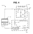
- FIG. 3 shows the pyroelectric capacitor 12 and the heater 20 as part of an integrated circuit 112.
- the heater 20 includes a thin film resistor in contact with the pyroelectric capacitor 12.
- a thick field oxide 114 may be formed on a silicon substrate 116, the thin film resistor is formed over the field oxide 114, and the pyroelectric capacitor 12 is formed on the thin film resistor.
- This structure has good thermal coupling between the heater 20 and the pyroelectric capacitor 12. It also has poor thermal coupling to the substrate 116 so that most of the heat pulses from the heater 20 are coupled into the pyroelectric material.
- a diffused resistor in the substrate costs less to implement but requires more power to heat the pyroelectric material.
- Transistors may be used instead of resistors to deliver heat to the pyroelectric capacitor 12.
- Power delivered to the heater 20 may come from the VDD power supply of the integrated circuit 112 or from a separate heater power supply if it is desirable to separate the power sources.
- the area configuration of the pyroelectric material may follow the area configuration of the heater 20. If the crystal is bonded to the surface of the integrated circuit, a regular shape (e.g., square or rectangular) is preferred. If a pyroelectric crystal is grown or deposited on the substrate and patterned using a photolithography process, the surface shape of the crystal could be any complex shape that covers the heater 20. During the cooling cycles, heat from the pyroelectric material is dissipated to integrated circuit packaging materials.
- the thin film resistor or other heat-dissipative element may be made from almost any resistive material, such as poly silicon or tungsten. If the pyroelectric capacitor crystal is mechanically placed on the chip, adding a conductor to the top of the crystal could be done with a discrete wire or as part of a beam-lead process.
- the control circuit 22 and the output circuit 24 may be fabricated in the silicon substrate 116.
- the output circuit 24 includes a diode 118 and output filter 120 (e.g., a capacitor and resistors) for rectifying the output of the pyroelectric capacitor 12.
- the output circuit 24 further includes a sense circuit 122 for sensing a voltage level at an output (Vout) of the output circuit 24, and providing feedback (Fbk) to the control circuit 22.
- the sense circuit 122 is shown as a resistor ladder, which also forms a part of the output filter 120.
- the control circuit 22 includes a comparator 124 for comparing the sensed output voltage to the reference voltage (Vref), and a pulse generator 126 for delivering a series of power pulses to the heater 20 in response to an output from the comparator 124.
- the pulse generator 126 may include a clock and a gate. The clock generates pulses at a fixed frequency, and the gate allows certain pulses to pass when the output voltage (Vout) is less than the reference voltage (Vref).
- a more sophisticated control circuit could be used instead to control the amplitude and frequency of the electrical pulses to the heater 20.
- a variable frequency/amplitude generator could be used. Amplitude could be varied to control the instantaneous power delivered to the heater 20 per heating cycle, and the frequency could be varied to control the duration of the heating and cooling periods.
- Increasing the heating duty cycle (that is, increasing the ratio of heating cycle period to the period of a full cycle) will increase the output voltage (Vout), and decreasing the heating duty cycle will decrease the output voltage (Vout).
- Increasing the frequency will raise the average temperature of the pyroelectric capacitor 12. By operating at a larger temperature difference between the pyroelectric capacitor and ambient, the cooling cycle will be more efficient and should result in a higher output voltage (Vout).
- the control circuit 22 also includes a diode 128 for providing charge recovery during cooling cycles.
- the diode 128 is connected between the pyroelectric capacitor 12 and a source that provides a recovery voltage (Vg).
- Vg recovery voltage
- the capacitor voltage (Vc) is greater than the output voltage (Vout)
- Vg recovery voltage
- a current flows from the recovery voltage source, through the diode 128 and to the pyroelectric capacitor 12, whereby charge is recovered.
- the sources that supply the reference voltage (Vref) and the recovery voltage (Vg) may be internal or external to the integrated circuit 112.
- the recovery voltage (Vg) could be set to a bias voltage (such as the normal low voltage power supply VDD) or some other recovery voltage to limit the lower level of voltage on the pyroelectric capacitor 12 and to help speed up the build-up of the capacitor voltage (Vc) during the heating cycle.
- the control circuit 22 is neither recovering charge or charging the capacitor during the time period when the capacitor voltage (Vc) swings between the output voltage (Vout) and the recovery voltage (Vg). A higher recovery voltage (Vg) results in better efficiency of the power supply 10. It would be desirable to use the highest available power supply potential to set the reference voltage (Vg).
- FIG. 5 shows a general method of using the circuit just described.
- Heat pulses are sent to the pyroelectric capacitor (210); capacitor voltage is compared to a reference voltage (212); and the heat pulses are adjusted in response to the comparison (214).
- the heat pulses may be adjusted by varying pulse width, amplitude, frequency, etc.
- Applications include, without limitation, field emitter memory devices and radiation detectors.
Landscapes
- Engineering & Computer Science (AREA)
- Power Engineering (AREA)
- Semiconductor Integrated Circuits (AREA)
- Photometry And Measurement Of Optical Pulse Characteristics (AREA)
- Fire-Detection Mechanisms (AREA)
Applications Claiming Priority (2)
| Application Number | Priority Date | Filing Date | Title |
|---|---|---|---|
| US892251 | 2001-06-26 | ||
| US09/892,251 US6657358B2 (en) | 2001-06-26 | 2001-06-26 | Power supply including pyroelectric capacitor |
Publications (3)
| Publication Number | Publication Date |
|---|---|
| EP1276220A2 true EP1276220A2 (fr) | 2003-01-15 |
| EP1276220A3 EP1276220A3 (fr) | 2004-01-14 |
| EP1276220B1 EP1276220B1 (fr) | 2010-06-30 |
Family
ID=25399645
Family Applications (1)
| Application Number | Title | Priority Date | Filing Date |
|---|---|---|---|
| EP02253483A Expired - Lifetime EP1276220B1 (fr) | 2001-06-26 | 2002-05-17 | Alimentation d'énergie avec condensateur pyroélectrique |
Country Status (7)
| Country | Link |
|---|---|
| US (1) | US6657358B2 (fr) |
| EP (1) | EP1276220B1 (fr) |
| JP (1) | JP2003068867A (fr) |
| KR (1) | KR20030001346A (fr) |
| CN (1) | CN100466314C (fr) |
| DE (1) | DE60236831D1 (fr) |
| TW (1) | TWI281309B (fr) |
Families Citing this family (14)
| Publication number | Priority date | Publication date | Assignee | Title |
|---|---|---|---|---|
| JP2002092186A (ja) * | 2000-09-18 | 2002-03-29 | Nidek Co Ltd | 医療情報共有化方法及び医療情報共有化システム |
| DE10222616A1 (de) * | 2002-05-17 | 2003-12-04 | Univ Albert Ludwigs Freiburg | Fingerabdruck-Verifikationsmodul |
| US7081684B2 (en) * | 2003-10-06 | 2006-07-25 | Hewlett-Packard Development Company, L.P. | Converting heat generated by a component to electrical energy |
| DE102009008998B4 (de) | 2008-02-21 | 2011-01-20 | Institut für Luft- und Kältetechnik gemeinnützige Gesellschaft mbH | Verfahren und Anordnung zur Erzeugung von Hochspannungen und Verwendung eines demgemäßen Hochspannungsgenerators |
| US8536528B2 (en) * | 2008-12-12 | 2013-09-17 | Baker Hughes Incorporated | System and method for downhole voltage generation |
| IT1394829B1 (it) * | 2009-07-17 | 2012-07-20 | Fabiani | Dispositivo e metodo per la trasmissione di un segnale attraverso un corpo di materiale dielettrico. |
| US8519595B2 (en) | 2010-09-02 | 2013-08-27 | Ut-Battelle, Llc | MEMS based pyroelectric thermal energy harvester |
| CN102442074B (zh) * | 2010-09-30 | 2014-09-10 | 兄弟工业株式会社 | 墨水盒和使用墨水盒的记录设备 |
| KR101035992B1 (ko) * | 2010-12-23 | 2011-05-23 | 주식회사 정원엘피 | 태양전지 가로등 |
| US20130154274A1 (en) * | 2011-12-19 | 2013-06-20 | Robert Vincent | Systems for electrical power generation |
| US8324783B1 (en) | 2012-04-24 | 2012-12-04 | UltraSolar Technology, Inc. | Non-decaying electric power generation from pyroelectric materials |
| US11384966B2 (en) | 2014-03-21 | 2022-07-12 | The Charles Stark Draper Laboratory, Inc. | Cooler with remote heat sink |
| GB2547487B (en) * | 2016-02-12 | 2020-08-12 | Univ Bath | Apparatus and method for generating electrical energy |
| CN109715408B (zh) * | 2016-09-08 | 2021-01-08 | 惠普发展公司,有限责任合伙企业 | 打印机干燥器监测器 |
Family Cites Families (15)
| Publication number | Priority date | Publication date | Assignee | Title |
|---|---|---|---|---|
| US2258377A (en) * | 1940-07-11 | 1941-10-07 | John C Collins | Chuck and tool holding device |
| US4024560A (en) * | 1975-09-04 | 1977-05-17 | Westinghouse Electric Corporation | Pyroelectric-field effect electromagnetic radiation detector |
| US4365106A (en) * | 1979-08-24 | 1982-12-21 | Pulvari Charles F | Efficient method and apparatus for converting solar energy to electrical energy |
| US4453405A (en) * | 1982-05-24 | 1984-06-12 | Trustees Of The University Of Pennsylvania | Pyroelectric vorticimeter |
| JPS60125530A (ja) * | 1983-12-09 | 1985-07-04 | Kureha Chem Ind Co Ltd | 赤外線センサ |
| US4647836A (en) * | 1984-03-02 | 1987-03-03 | Olsen Randall B | Pyroelectric energy converter and method |
| US4608865A (en) * | 1984-12-05 | 1986-09-02 | The Regents Of The University Of California | Integrated pyroelectric sensor and method |
| SU1342200A1 (ru) * | 1985-10-31 | 1995-10-20 | Л.Л. Горелик | Течеискатель |
| US4792667A (en) * | 1987-03-27 | 1988-12-20 | Sicpa Holding, S.A. | Method and apparatus for authenticating documents utilizing poled polymeric material |
| GB9010440D0 (en) * | 1990-05-09 | 1990-06-27 | Plessey Res Caswell | Pyroelectric anemometer |
| FR2683106B1 (fr) * | 1991-10-25 | 1993-12-03 | Thomson Brandt Armements | Systeme de transmission et de conversion electrique de signaux optiques de puissance modules en frequence. |
| US5644184A (en) * | 1996-02-15 | 1997-07-01 | Thermodyne, Inc. | Piezo-pyroelectric energy converter and method |
| US5860741A (en) * | 1996-03-25 | 1999-01-19 | Oriental System Technology, Inc. | Absolute radiation thermometer |
| FR2755526B1 (fr) * | 1996-11-05 | 1999-01-22 | Thomson Csf | Systeme de lecture d'empreintes digitales avec resistances de chauffage integrees |
| US6528898B1 (en) * | 1998-12-14 | 2003-03-04 | Her Majesty The Queen In Right Of Canada, As Represented By The Minister Of Natural Resources | Pyroelectric conversion system |
-
2001
- 2001-06-26 US US09/892,251 patent/US6657358B2/en not_active Expired - Fee Related
-
2002
- 2002-05-07 TW TW091109501A patent/TWI281309B/zh not_active IP Right Cessation
- 2002-05-17 EP EP02253483A patent/EP1276220B1/fr not_active Expired - Lifetime
- 2002-05-17 DE DE60236831T patent/DE60236831D1/de not_active Expired - Lifetime
- 2002-06-25 KR KR1020020035555A patent/KR20030001346A/ko not_active Ceased
- 2002-06-25 JP JP2002183841A patent/JP2003068867A/ja active Pending
- 2002-06-26 CN CNB021231605A patent/CN100466314C/zh not_active Expired - Fee Related
Non-Patent Citations (1)
| Title |
|---|
| FUKUDA T ET AL.: "Micro optical robotic system with cordless optical power supply", INTELLIGENT ROBOTS AND SYSTEMS '93, IROS '93. PROCEEDINGS OF THE 1993 IEIEE/RSJ INTERNATIONAL CONFERENCE ON YOKOHAMA, 26 July 1993 (1993-07-26), pages 1703 - 1708 |
Also Published As
| Publication number | Publication date |
|---|---|
| EP1276220B1 (fr) | 2010-06-30 |
| CN1395351A (zh) | 2003-02-05 |
| DE60236831D1 (de) | 2010-08-12 |
| JP2003068867A (ja) | 2003-03-07 |
| TWI281309B (en) | 2007-05-11 |
| US6657358B2 (en) | 2003-12-02 |
| EP1276220A3 (fr) | 2004-01-14 |
| US20020195952A1 (en) | 2002-12-26 |
| KR20030001346A (ko) | 2003-01-06 |
| CN100466314C (zh) | 2009-03-04 |
Similar Documents
| Publication | Publication Date | Title |
|---|---|---|
| US6657358B2 (en) | Power supply including pyroelectric capacitor | |
| US3308271A (en) | Constant temperature environment for semiconductor circuit elements | |
| CA2283963C (fr) | Oscillateur piezo-electrique | |
| US5838187A (en) | Integrated circuit thermal shutdown system utilizing a thermal sensor | |
| US5188286A (en) | Thermoelectric piezoelectric temperature control | |
| US6182902B1 (en) | Device and method for automatically controlling rotating speed of fan cooler | |
| US4467611A (en) | Thermoelectric power generating device | |
| JPH07209091A (ja) | マイクロプロセッサの温度に関する検知信号提供装置 | |
| EP1849234B1 (fr) | Oscillateur basé sur la diffusion thermique | |
| US20060250193A1 (en) | Integrated CMOS high precision piezo-electrically driven clock | |
| EP3508829B1 (fr) | Circuit intégré de capteur thermique, résistance utilisé dans un capteur thermique et procédé de détection de température | |
| CN109219908A (zh) | 散热器上加热器 | |
| EP0310101A2 (fr) | Capteur de température | |
| CN102590579A (zh) | 用于di/dt电流感测的方法及装置 | |
| EP0803133B1 (fr) | Transistor oscillant auto-stabilisant regule par un filament | |
| EP0109712B1 (fr) | Détecteur thermique pour l'infrarouge | |
| US5949121A (en) | Temperature-indicating field effect transistor | |
| US6326858B1 (en) | Oscillator circuit with thermal feedback | |
| EP1682858A1 (fr) | Capteur thermique integre pour transistors micro-ondes | |
| CN1262813A (zh) | 定时电路 | |
| JP3239052B2 (ja) | 半導体集積回路 | |
| CN103887025B (zh) | 包含非承载电流的热传导金属箔部分的金属电阻器 | |
| CN103885520B (zh) | 一种具有静电屏蔽的温度补偿金属电阻器 | |
| JP3180409B2 (ja) | 半導体装置 | |
| JP4667614B2 (ja) | カロリメータとその駆動方法 |
Legal Events
| Date | Code | Title | Description |
|---|---|---|---|
| PUAI | Public reference made under article 153(3) epc to a published international application that has entered the european phase |
Free format text: ORIGINAL CODE: 0009012 |
|
| AK | Designated contracting states |
Kind code of ref document: A2 Designated state(s): AT BE CH CY DE DK ES FI FR GB GR IE IT LI LU MC NL PT SE TR |
|
| AX | Request for extension of the european patent |
Free format text: AL;LT;LV;MK;RO;SI |
|
| PUAL | Search report despatched |
Free format text: ORIGINAL CODE: 0009013 |
|
| AK | Designated contracting states |
Kind code of ref document: A3 Designated state(s): AT BE CH CY DE DK ES FI FR GB GR IE IT LI LU MC NL PT SE TR |
|
| AX | Request for extension of the european patent |
Extension state: AL LT LV MK RO SI |
|
| 17P | Request for examination filed |
Effective date: 20040405 |
|
| AKX | Designation fees paid |
Designated state(s): DE GB |
|
| 17Q | First examination report despatched |
Effective date: 20070712 |
|
| RIC1 | Information provided on ipc code assigned before grant |
Ipc: H02N 11/00 20060101AFI20090409BHEP Ipc: H02M 3/00 20060101ALN20090409BHEP |
|
| GRAP | Despatch of communication of intention to grant a patent |
Free format text: ORIGINAL CODE: EPIDOSNIGR1 |
|
| GRAS | Grant fee paid |
Free format text: ORIGINAL CODE: EPIDOSNIGR3 |
|
| GRAA | (expected) grant |
Free format text: ORIGINAL CODE: 0009210 |
|
| AK | Designated contracting states |
Kind code of ref document: B1 Designated state(s): DE GB |
|
| REG | Reference to a national code |
Ref country code: GB Ref legal event code: FG4D |
|
| REF | Corresponds to: |
Ref document number: 60236831 Country of ref document: DE Date of ref document: 20100812 Kind code of ref document: P |
|
| PLBE | No opposition filed within time limit |
Free format text: ORIGINAL CODE: 0009261 |
|
| STAA | Information on the status of an ep patent application or granted ep patent |
Free format text: STATUS: NO OPPOSITION FILED WITHIN TIME LIMIT |
|
| 26N | No opposition filed |
Effective date: 20110331 |
|
| REG | Reference to a national code |
Ref country code: DE Ref legal event code: R097 Ref document number: 60236831 Country of ref document: DE Effective date: 20110330 |
|
| REG | Reference to a national code |
Ref country code: GB Ref legal event code: 732E Free format text: REGISTERED BETWEEN 20120329 AND 20120404 |
|
| PGFP | Annual fee paid to national office [announced via postgrant information from national office to epo] |
Ref country code: GB Payment date: 20130424 Year of fee payment: 12 Ref country code: DE Payment date: 20130423 Year of fee payment: 12 |
|
| REG | Reference to a national code |
Ref country code: DE Ref legal event code: R119 Ref document number: 60236831 Country of ref document: DE |
|
| GBPC | Gb: european patent ceased through non-payment of renewal fee |
Effective date: 20140517 |
|
| REG | Reference to a national code |
Ref country code: DE Ref legal event code: R119 Ref document number: 60236831 Country of ref document: DE Effective date: 20141202 |
|
| PG25 | Lapsed in a contracting state [announced via postgrant information from national office to epo] |
Ref country code: DE Free format text: LAPSE BECAUSE OF NON-PAYMENT OF DUE FEES Effective date: 20141202 |
|
| PG25 | Lapsed in a contracting state [announced via postgrant information from national office to epo] |
Ref country code: GB Free format text: LAPSE BECAUSE OF NON-PAYMENT OF DUE FEES Effective date: 20140517 |