EP1277436A1 - Instrument pour observer la peau ou les cheveux - Google Patents
Instrument pour observer la peau ou les cheveux Download PDFInfo
- Publication number
- EP1277436A1 EP1277436A1 EP02291574A EP02291574A EP1277436A1 EP 1277436 A1 EP1277436 A1 EP 1277436A1 EP 02291574 A EP02291574 A EP 02291574A EP 02291574 A EP02291574 A EP 02291574A EP 1277436 A1 EP1277436 A1 EP 1277436A1
- Authority
- EP
- European Patent Office
- Prior art keywords
- skin
- light
- observation
- area
- examined
- Prior art date
- Legal status (The legal status is an assumption and is not a legal conclusion. Google has not performed a legal analysis and makes no representation as to the accuracy of the status listed.)
- Granted
Links
Images





Classifications
-
- A—HUMAN NECESSITIES
- A61—MEDICAL OR VETERINARY SCIENCE; HYGIENE
- A61B—DIAGNOSIS; SURGERY; IDENTIFICATION
- A61B5/00—Measuring for diagnostic purposes; Identification of persons
- A61B5/44—Detecting, measuring or recording for evaluating the integumentary system, e.g. skin, hair or nails
- A61B5/448—Hair evaluation, e.g. for hair disorder diagnosis
-
- A—HUMAN NECESSITIES
- A61—MEDICAL OR VETERINARY SCIENCE; HYGIENE
- A61B—DIAGNOSIS; SURGERY; IDENTIFICATION
- A61B5/00—Measuring for diagnostic purposes; Identification of persons
- A61B5/44—Detecting, measuring or recording for evaluating the integumentary system, e.g. skin, hair or nails
- A61B5/441—Skin evaluation, e.g. for skin disorder diagnosis
-
- G—PHYSICS
- G01—MEASURING; TESTING
- G01N—INVESTIGATING OR ANALYSING MATERIALS BY DETERMINING THEIR CHEMICAL OR PHYSICAL PROPERTIES
- G01N21/00—Investigating or analysing materials by the use of optical means, i.e. using sub-millimetre waves, infrared, visible or ultraviolet light
- G01N21/84—Systems specially adapted for particular applications
-
- A—HUMAN NECESSITIES
- A61—MEDICAL OR VETERINARY SCIENCE; HYGIENE
- A61B—DIAGNOSIS; SURGERY; IDENTIFICATION
- A61B5/00—Measuring for diagnostic purposes; Identification of persons
- A61B5/0059—Measuring for diagnostic purposes; Identification of persons using light, e.g. diagnosis by transillumination, diascopy, fluorescence
- A61B5/0077—Devices for viewing the surface of the body, e.g. camera, magnifying lens
-
- A—HUMAN NECESSITIES
- A61—MEDICAL OR VETERINARY SCIENCE; HYGIENE
- A61B—DIAGNOSIS; SURGERY; IDENTIFICATION
- A61B5/00—Measuring for diagnostic purposes; Identification of persons
- A61B5/103—Measuring devices for testing the shape, pattern, colour, size or movement of the body or parts thereof, for diagnostic purposes
- A61B5/1032—Determining colour of tissue for diagnostic purposes
-
- A—HUMAN NECESSITIES
- A61—MEDICAL OR VETERINARY SCIENCE; HYGIENE
- A61B—DIAGNOSIS; SURGERY; IDENTIFICATION
- A61B5/00—Measuring for diagnostic purposes; Identification of persons
- A61B5/44—Detecting, measuring or recording for evaluating the integumentary system, e.g. skin, hair or nails
- A61B5/441—Skin evaluation, e.g. for skin disorder diagnosis
- A61B5/443—Evaluating skin constituents, e.g. elastin, melanin, water
-
- A—HUMAN NECESSITIES
- A61—MEDICAL OR VETERINARY SCIENCE; HYGIENE
- A61B—DIAGNOSIS; SURGERY; IDENTIFICATION
- A61B5/00—Measuring for diagnostic purposes; Identification of persons
- A61B5/44—Detecting, measuring or recording for evaluating the integumentary system, e.g. skin, hair or nails
- A61B5/441—Skin evaluation, e.g. for skin disorder diagnosis
- A61B5/444—Evaluating skin marks, e.g. mole, nevi, tumour, scar
-
- G—PHYSICS
- G01—MEASURING; TESTING
- G01N—INVESTIGATING OR ANALYSING MATERIALS BY DETERMINING THEIR CHEMICAL OR PHYSICAL PROPERTIES
- G01N21/00—Investigating or analysing materials by the use of optical means, i.e. using sub-millimetre waves, infrared, visible or ultraviolet light
- G01N21/84—Systems specially adapted for particular applications
- G01N2021/8444—Fibrous material
Definitions
- the present invention relates to the evaluation of characteristics of the body typology, including appearance characteristics such as shine, color and skin relief, for example.
- dermatoscopes that contain a magnification system and integrated lighting means making it possible to make precise observations.
- these dermatoscopes are not intended to deliver an image other than a simple enlargement of the observed area.
- the lighting characteristics are likely to vary from one dermatoscope to another, which is not too troublesome when is to observe a skin defect but is unsatisfactory when it comes to evaluating appearance characteristics such as gloss or color, for example.
- the invention aims in particular, according to one of its aspects, to meet this need.
- this device being able to characterize, according to one aspect of the invention, that it makes it possible to observe directly to an area of the skin or hair and includes means for generate at least two images of an examined area that differ in different ways from the magnification or light intensity of an integrated source.
- Said images can be generated so that they can be compared between them, either simultaneously or successively.
- Said images can be generated successively by acting between two observations on an organ of the device to vary a characteristic other than the magnification or luminous intensity of the source.
- Said images can also be generated simultaneously when the device is arranged to simultaneously produce, with optical elements, two different images of the observed area.
- Said images may differ for example by the orientation of a direction polarization of an analyzer, by the degree of directivity of the incident light, by the direction of incidence of incident light, by the color of light, by filtering light from the area under examination, or by mechanical action exerted on the examined area, such as pressure, wrinkling or stretching.
- Said images may or may not be generated to follow the evolution of a area examined over time.
- the observation device can make it possible to follow the evolution of a zone of skin over time, generating at a given moment at least two images of the area skin, differing only in the magnification or luminous intensity of a skin integrated source, and generating, for example a month later, at least two images of the same skin area, differing only in magnification or intensity of an integrated source.
- the device according to the invention allows direct observation, that is to say in looking through the observation device the examined area, without acquisition by a camera, a video camera or other types of electronic sensors. Its cost of production can thus remain compatible with a wide diffusion.
- the observation can be made under conditions predefined illumination, it is possible to quantify the observed characteristic of a relatively accurate and reproducible way.
- the device comprises an optical system arranged to produce an enlarged image of the examined area. It is thus possible to evaluate skin characteristics that are difficult to see with the naked eye, such as example its desquamation.
- the device is arranged to to reduce or eliminate the brightness of at least part of the area examined, which may make it easier, for example, to observe the color of the skin or hair, without being bothered by reflections.
- the deletion or decrease of brilliance can also be helpful in observing the color of light that is backscattered, from deep layers of the epidermis or hair, and depends on the state of these layers.
- the latter may comprise a rotary polarizer or two polarizers having different polarization directions, one of which may be perpendicular to the direction of polarization of the incident light and the other parallel.
- the examined area can be illuminated using a lighting means for illuminating it with different inclinations of the incident light, for example to observe it under diffuse lighting or under lighting shaving.
- Shading lighting can give relief information and diffused lighting information on the homogeneity of the color.
- the device comprises at least one screen able to be interposed between a light source and the examined area, so as not to allow lighting of the latter only by diffusion of light under the screen, in the examined tissue.
- This screen can be mobile, movable from a first position in which it is removed from a surface bordering the examined area to a second position in which it comes into contact with said surface.
- We can thus observe the skin or hair by transillumination, that is to say that the illumination of a zone of skin or hair is made by light from adjacent areas, skin or hair used as a light guide, and in particular to obtain transparency information, this information which may be combined, where appropriate, with other information previous observations that occurred under different illumination conditions.
- the screen can still be brought into a position in which it allows illumination shaving the area examined.
- the screen may comprise a tubular wall extending, at during use, around the area examined.
- the screen which may be of non-section circular, may have a conical or pyramidal portion converging towards the zone examined.
- the device may comprise at least one spring to recall the screen in a rest position, in the absence of use.
- the device may comprise a reticle, in particular for measuring the distance from which the scattering of light is no longer visible, when one observed by transillumination.
- the device comprises at least one filter colored.
- This filter can be blue in order to highlight the pigmentation of the skin, for example.
- the device comprises at least one polarizer.
- This polarizer can be placed on the path of light, between a source of light and the area examined.
- the device may also include at least one polarizer placed on the path of light between the examined area and an eye of the observer.
- the device may comprise at least two orientation polarizers different, juxtaposed, placed on the path of light between the examined area and an eye of the observer. It is thus possible to observe a contrast between two zones of the image, and enjoy the rather high sensitivity of the human eye to a contrast.
- the device can have at least one polarizer rotatably mounted so as to allow the user to change the orientation of its direction of polarization with respect to a direction of reference.
- the device may comprise for example a handle comprising an actuating member such as a wheel, for example, allowing change the orientation of the polarizer with the same hand that holds the handle.
- the device can be arranged to allow illumination of the examined area by natural light.
- the device may in particular comprise a skirt made of transparent plastic, one edge of which may extend around the examined area.
- the device may also include at least one integrated light source.
- This integrated light source may comprise at least one chosen light element among the following: incandescent lamp, light-emitting diode, fluorescent lamp fluorescence.
- the device may comprise lighting elements illuminating in respective ranges of different wavelengths.
- the device can for example have a source that reproduces the spectral characteristics of natural light, which may comprise slightly colored light-emitting diodes.
- the device may comprise a plurality of light elements and control means permitting selectively supplying at least a portion of these light elements.
- the device observation can include light elements arranged circularly.
- the device may further comprise a housing for receiving one or several batteries.
- a housing for receiving one or several batteries.
- Such a housing may have a substantially perpendicular to a direction of observation of the area examined.
- the device may comprise a window for compressing the skin in the area examined to expel the blood.
- a window may be made of glass or transparent plastic material, possibly colored.
- Such a window may constitute a removable accessory or an element permanently attached to the device, movable between a active position in which it interposes itself between the skin and the path of light towards the observer and an inactive position, in which the window is not on the path of the light towards the observer.
- the device may comprise a ring allowing the adaptation of a device photographic.
- the device is associated with an atlas comprising a plurality of reference images. These images can be arranged on a single support or be connected together. The images can each be associated with an alphanumeric indication.
- the device can also be associated with a computer for displaying reference images.
- the observation device may, moreover, comprise or be used in combination with a tool for folding or stretching the skin.
- This tool may include, for example, two parts intended to be applied to the skin and can be moved apart or together to stretch or skin.
- the tool can have on each part intended to be applied to the skin a strip of a double-sided adhesive allowing it to adhere to the skin.
- the tool can be attached to the observation device.
- At least one difference between the images observed through the device observation can be the degree of wrinkling or stretching of the skin.
- the tool for folding or stretching the skin can also be used independently of the viewing device.
- the object of the invention is therefore, independently of the observation device mentioned above, a skin assessment tool consisting of two parts intended to be applied on the skin and connected to each other by a link allowing them to be moved relative to each other between a laying position of the tool on the skin, in which the two parts are close together and a position of stretching of the skin, in which the two parts are separated, the connection comprising at least one resilient member requesting the two parts apart.
- the two parts can be brought together against the action of the organ elastic and then placed on the skin and relaxed.
- the elastic member can solicit them then spread out or assist the user who manually bypasses them.
- the link that connects the two parts can be configured to allow the user to move them away from a predetermined distance.
- the link can for example comprise at least one stop determining the maximum spacing of the two parts.
- the link can be configured to create a hard point in the displacement of the two parts when they reach their maximum spacing.
- the connection may for example comprise at least one locking member which engages when the spacing is maximum.
- each of the two parts may have a general form in U when the tool is viewed from above, in a direction perpendicular to the direction relative displacement of two parts.
- Both parts can be configured to form between them, when in a close position, a window of observation of the skin.
- this window is formed by the two concavities of the U.
- a material for making an impression for example a wax or a resin
- the skin stretching tool can be used especially to make appear microcysts or other skin defects.
- the stretching tool can still be configured to allow measure the distance between the two parts applied to the skin under the sole action of the elastic member.
- a greater or lesser separation of the two parts may ability to stretch more or less of the skin.
- one of the aforementioned stems may have graduations allowing the user to carry out a measurement of the distance between the two parts.
- the subject of the invention is also a method in which the stretching tool defined above is used.
- the separation of the two parts can take place for example under the sole effect of at least one elastic member and / or under the effect of a spreading action of a user.
- Both parts can be maintained with a predetermined spacing during the observation of the skin.
- the observed images can be compared with reference images, to select one of them.
- the contrast between light that has a reflection component and a backscattered component and light which has essentially a backscattered component by illuminating the examined area with polarized light and observing it with an analyzer.
- Reference images can be displayed on the screen of a computer, as indicated above.
- the reference images can in particular be transmitted to the computer from a server via a computer network, before being displayed on said screen.
- the method may further include the step of transmitting to server an indication representative of the selected reference image.
- the server can then be programmed to establish a diagnosis, for example, or to advocate a cosmetic or care product.
- a method is evaluation of a characteristic of the body typology, we carry out a treatment, in particular cosmetic, which may have an effect on said characteristic, then a new evaluation is carried out to detect a possible evolution of the said characteristic and determine the effectiveness of the treatment.
- the types of observation chosen may include (i) and (ii), (v) and (vi), (vii) and viii), ix) and x) or xi) and xii).
- the process may comprise the step of, before observing a skin area using the device described above, apply a tool for stretching or wrinkling the skin, for example a tool as defined previously, on the skin area and stretch or wrinkle the area of skin.
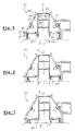
- the optical instrument 10 shown in FIGS. 1 to 4 is intended for the observation of the skin P or the hair and comprises a support 11 to be placed on the surface to be observed, a mobile assembly 12 that can be moved relative to the support 11 along an axis X, and a handle 13 allowing the gripping of the instrument by a user, this handle 13 being fixed relative to the support 11 and housing internally one or more batteries or accumulators 14.
- An elastic return system interacts between the support 11 and the assembly movable 12, so as to recall the latter in a rest position, corresponding to FIG. 1, in which the assembly 12 bears against the handle 13.
- this return system comprises several springs 15 while working in compression, bearing at one end against a shoulder of the support 11 and at the other end against the assembly 12.
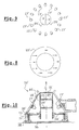
- the latter comprises a plurality of light emitters 17 constituted, in the example described, by white light-emitting diodes distributed all around the X axis, as shown in FIG. 2, so as to produce either a diffuse illumination of the Z zone examined when all the light emitters are powered, ie a light in one or more particular directions, if only part of the transmitters bright is powered.
- the light emitters 17 are supplied with electricity thanks to to the batteries 14 by a supply circuit 30, shown very schematically, in a concern for clarity of the drawing. This supply circuit 30 is connected to a control circuit 31.
- An optical element 23 is placed on the path of light between the emitters 17 and the zone examined Z.
- This optical element 23 is constituted in the example considered by a translucent annular piece, which may be colorless or colored, and which constitutes a broadcaster.
- the tube 18 is extended below by a screen 27, whose free edge 28 delimits the field of observation.
- the optical instrument 10 makes it possible to carry out successive observations, in different lighting conditions, from the same surface.
- the examined zone Z can be diffusely and omnidirectionally lit by all light emitters 17.
- the screen 27 can be brought closer to the examined zone Z thanks to the mobility of the assembly 12 relative to the support 11, as shown in Figure 3.
- the lower edge 28 of the screen 27 could be moved closer by the user exerting a sufficient downward pressure on the assembly 12, against the recall action 15. It is then possible to obtain a lighting grazing of the zone examined Z, capable of to bring out more the relief of the skin or the hair and to increase the shine.
- the user can also fully press the assembly 12 so as to bring the screen 27 in contact with the surface of the skin or hair, as shown in Figure 4.
- the examined area Z is illuminated only by transillumination, ie by diffusion of light into the tissue observed, which makes it possible, for example, to obtain information on its transparency, color or its irrigation by the blood. Power supply of light emitters 17 can remain unchanged between different observations.
- the control circuit 31 may consist of a simple switch electrical controlling all-or-nothing power of all transmitters 17 or by a more complex system, allowing for example to feed selectively certain light emitters 17, so as to obtain, for example, a lighting directional or multidirectional, fixed or rotating, or even in the case where transmitters luminaires would have diodes of different colors or capable of emitting variable wavelengths, to modify the spectral characteristics of the light illuminate the area examined.
- FIGS. 5 to 7 show an optical instrument 10 'which corresponds to to a variant of the instrument 10 described above.
- the instrument 10 ' comprises a body 16' which is fixed and a screen 27 'which is movable relative to the body 16' along the axis X, to modify the conditions of illumination of the observed zone Z, to allow for example to pass from multidirectional diffuse lighting to grazing lighting, as shown in Figure 6, even to transillumination illumination, as illustrated in FIG. 7.
- a polarizer 23 'shown in isolation in FIG. 8 is placed on the path of the light between the light emitters 17 'and the observed zone Z.
- This polarizer 23' has an annular shape and a single polarization direction, indicated by arrows in Figure 8.
- the screen 27 ' is slidably mounted on a tube 18' which supports lenses 20 ', 21' and polarizers 24 ', 25' and can be moved by means of a protruding tab 30 ' outside the instrument, passing through a slot 31 'of the body 16', on which are mounted the light emitters 17 '. These are arranged in the same way as the light emitters 17 of the previous set.
- An advantage of the instrument 10 ' do not change the distance between the examined area and the lenses 20 ', 21' during change of configuration of the lighting by moving the screen 27 '.
- two polarisers 24 'and 25' each shaped half disc and joined by their base so as to form an analyzer disc, are placed in the path of light in the tube 18 ', in the image focal plane of the lens 20'.
- the Polarization directions of the polarizers 24 'and 25' are perpendicular to each other and indicated by arrows in Figure 9.
- the analyzer constituted by the polarizers 24 'and 25' makes it possible to obtain a half-image with brilliance and half-image without brilliance, choosing the direction of polarization of one of the half-discs 24 'and 25' parallel to the direction of polarization of the polarizer 23 '.
- the polarizers 24 'and 25' are replaced by a polarizer rotatably mounted about the X axis so that it can coincide with its direction of polarization with the direction of polarization of incident light and secondly then direct its direction of polarization perpendicular to the direction of polarization of the polarizer 23 '.
- the two-part analyzer 24 ', 25' makes it possible to obtain an image contrast, and therefore to take advantage of the increased sensitivity of the human eye to a contrast.
- This window 35 can be made of plastic for example, and have a rim 36 allowing its positioning on the instrument.
- the window 35 constitutes a removable accessory but it is not beyond the scope of the present invention when the window is retractable and remains attached to the instrument in its retracted position. when is in place on the instrument, the window 35 compresses the skin and expels the blood ; we can thus make observations of the skin by decreasing the incidence of the color of the blood on the color of the skin.
- a series of observations can be made without the window 35, then to a new series of observations with the window 35, under different types of lighting or polarizations and compare the results to draw a useful information.
- FIGS. 11, 13 and 14 show an instrument 40, one of which particularity, compared to the instruments 10 and 10 'previously described, is to have no built-in lighting
- the instrument 40 comprises a body 41 extended downwards by a skirt transparent 42.
- the body 41 serves as support for an optical assembly comprising lenses 43, 44 carried by a tube 45, snapped into the body 41.
- the optical assembly comprises also a reticle 46 for measuring a distance on the examined area. This the reticle is printed, in the example described and shown separately in FIG. glass 47 placed on the path of light from the area examined.
- a colored filter 46 is removably mounted on the body 41.
- this filter is blue, so as to highlight, if desired, the pigmentary spots.
- a screen consisting of an opaque ring 48 can slide on the body 41 and on the transparent skirt 42, between a completely retracted position, corresponding to FIG. 11, in which the ring 48 does not cover the transparent skirt 42, a intermediate position corresponding to Figure 13, in which the ring 48 comes cover a major part of the transparent skirt 42, to allow illumination shaving the area examined, and a fully lowered position of the ring 48 corresponding to Figure 14, in which the latter completely covers the skirt transparent 42 and allows illumination by transillumination.
- flutes 49 and 50 are formed on the body 41 and the transparent skirt 42 so as to allow immobilization of the ring 48 in each of the different configurations described.
- the observer can measure by means of the reticle the distance from which the diffusion of the light is no longer visible and draw information on the transparency of the skin.
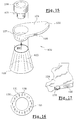
- FIG. 15 shows another example of an observation device 120 made according to the invention.
- This device 120 comprises a light source 122, a tip 123, and a optical assembly 121.
- the light source 122 comprises a handle 124 which forms a housing to inside which are arranged one or more batteries or accumulators, and a part openwork 127 in which can be engaged the optical assembly 121.
- the latter has an eyepiece 128 and one or more lenses represented, so as to produce an enlarged image, as well as a polarizer.
- the light source 122 comprises a selector 126 making it possible to illuminate the area to be observed with for example two different light intensities or two types different lighting, for example one simulating daylight and the other lighting incandescent.
- the tip 123 has a generally frustoconical shape with a base 129 having a diameter greater than the field of view of the optical assembly 121.
- the diameter of the base 129 is of the order of 40 mm and that of the field of view of the order of 30 mm. This avoids the pressure of contact of the tip 123 on the skin influences the appearance of the zone located in the field observation.
- the tip 123 may for example comprise a magnetic ring metal.
- the tip 123 may have at its end that comes into contact with the skin a removable ring.
- the light source 122 comprises, as can be seen in FIG. a plurality of electroluminescent diodes 130 whose axis is substantially parallel to that of the optical assembly 121. These light emitting diodes 130 are covered by a polarizer 131.
- the height of the nozzle 123 is chosen so that the lighting of the skin area located in the field of view is substantially homogeneous.
- the optical assembly 121 comprises two juxtaposed polarizers having perpendicular directions of polarization, as in the case of the embodiment described above, with reference to FIG. 9.
- the device 120 may comprise, as illustrated in FIG. 133 allowing the user to rotate the optical assembly 121 with the hand who holds the handle 124.
- Each image observed by means of an optical instrument for example one of those just described, this observation having taken place under conditions of specific illumination, can be compared with a reference image of an atlas containing several reference images, for example images expressing various degrees a characteristic of the body typology, especially the brilliance or the skin color, or images corresponding to varying degrees of contrast.
- a gloss atlas comprising several reference images 60 corresponding each to a degree of shine of the skin, quantified by an identifier alphanumeric 61.
- FIG. 19 shows very schematically an atlas of contrast or differences in brightness or color, with several images of reference 70, corresponding to different degrees of contrast or deviation that can be observed when using an analyzer such as that formed by the half-discs 24 ', 25 ', previously described. These images 70 are associated with identifiers alphanumeric 71, to identify them.
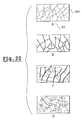
- FIG. 20 very schematically shows an atlas of cutaneous dryness, comprising several images 80, each associated with an identifier alphanumeric 81, the 80 images expressing various degrees of cutaneous dryness, ranging severe desquamation, characteristic of extremely dry skin, absence desquamation, translating normal skin.
- the reference images of an atlas can be printed on the same support or be connected together, as shown in Figure 21.
- Reference images can also be displayed on the screen of a computer 110, as illustrated in FIG. 22, each image being associated with an identifier alphanumeric.
- the results of an evaluation can be transmitted remotely by a network computer, including the Internet, by means of the computer 110 to a server 100, as shown in FIG. 23.
- the server 100 can be arranged to make a diagnosis according to the results transmitted and, if necessary, to recommend a product cosmetic or care.
- these images can be transmitted by the server 100, after connection of the user on the corresponding website.
- the invention can be implemented so as to monitor the effectiveness of a treatment, carrying out an evaluation after each phase of treatment and comparing the results of successive evaluations.
- a bank of multivector data combining a set of vectors each corresponding to a individual, each vector having at least two components each constituted by the result of an observation made using the same optical instrument.
- observation devices which have just been described can be used in combination with a tool for wrinkling or stretching the skin.
- FIGS. 24 and 25 show an example of a tool 140 making it possible to wrinkle or stretch the skin.
- the tool 140 shown in these figures has two parts 141 and 142 intended to be applied to the skin and connected by a connection allowing a relative displacement of one relative to the other.
- each of the parts 141 and 142 has a shape of U and the two parts define between them, when close together, as one can see it in FIG. 25, a window 137 for observation of the skin, this window being formed by the concavities of the U.
- connection between the parts 141 and 142 can be achieved in various ways.
- the link comprises two rods 143 and 144 of axes parallel.
- the rod 143 is fixed at one end in the portion 142 and can slide in a housing of the portion 141.
- the rod 143 has at its opposite end a head widened 145, connecting to the rest of the rod forming a groove 146.
- the rod 143 also comprises a second groove 147 and the portion 141 comprises a ball 148, biased by a spring 149 bearing against the rod 143.
- each ball 148 comes engage in the corresponding groove 146 which allows to immobilize the two parts 141 and 142 in their separated position.
- each ball 148 engages in the groove 147 corresponding.
- the tool 140 can be positioned on the skin by disposing an adhesive tape double-sided on each of the parts 141 and 142.
- the observation device can be configured to cooperate with the tool 140.
- the tool 140 may advantageously be provided, as illustrated in FIGS. 26 and 27, at least one elastic member constituted by example of a coil spring 150 engaged on one of the rods.
- Each rod 143 or 144 can be provided with its corresponding spring 150.
- the spring 150 can, as illustrated in FIG. 26, bear on one end against a ring 151 attached to one of the parts intended to be applied to the skin and come to bear on the other end against a shoulder 152 of the rod.
- the spring 150 is in the compressed state when the two parts 141 and 142 are close together.
- the tool can be placed on the skin while the parts 141 and 142 are brought together, each spring 150 being compressed then the parts 141 and 142 can deviate under the effect of the relaxation of the springs 150.
- At least one of the rods 143 or 144 may comprise graduations 153 which become apparent when parts 141 and 142 deviate, allowing precisely determine the spacing between the two parts 141 and 142.
- At least one elastic member arranged differently, for example a coil spring 160 working in compression, engaged on one of the rods 143 and 144, whose ends support in the bottom of housing 161 and 162 facing each other parts 141 and 142, these housings being made for example in the branches of the U, as illustrated in FIG. Figure 28.
- the device of Figure 28 may allow, where appropriate, to retain the grooves 146, 147 and the balls 148 of the example of FIGS. 24 and 25.
- the invention is not limited to the examples that have just been described and the structure of the optical instrument can be modified, particularly in replacing the light-emitting diodes by other means of illumination, such as by example of incandescent or fluorescent lamps.
- this screen can be constituted by an element attached, removably attached to the optical instrument.
Landscapes
- Health & Medical Sciences (AREA)
- Life Sciences & Earth Sciences (AREA)
- Pathology (AREA)
- Physics & Mathematics (AREA)
- General Health & Medical Sciences (AREA)
- Public Health (AREA)
- Engineering & Computer Science (AREA)
- Biomedical Technology (AREA)
- Heart & Thoracic Surgery (AREA)
- Medical Informatics (AREA)
- Molecular Biology (AREA)
- Surgery (AREA)
- Animal Behavior & Ethology (AREA)
- Biophysics (AREA)
- Dermatology (AREA)
- Veterinary Medicine (AREA)
- Chemical & Material Sciences (AREA)
- Analytical Chemistry (AREA)
- Biochemistry (AREA)
- General Physics & Mathematics (AREA)
- Immunology (AREA)
- Measurement Of The Respiration, Hearing Ability, Form, And Blood Characteristics Of Living Organisms (AREA)
- Measuring And Recording Apparatus For Diagnosis (AREA)
- Investigating Or Analysing Materials By Optical Means (AREA)
- Spectrometry And Color Measurement (AREA)
- Investigating Materials By The Use Of Optical Means Adapted For Particular Applications (AREA)
- Microscoopes, Condenser (AREA)
- Lenses (AREA)
Abstract
Description
- disposer sur la peau un outil comportant deux parties d'application reliées par une liaison permettant de modifier leur écartement, ces deux parties étant par exemple mobiles en translation l'une par rapport à l'autre, ces deux parties étant de préférence solidarisées à la peau chacune au moyen d'un ruban adhésif double face, alors qu'elles sont dans une position rapprochée,
- écarter les deux parties pour provoquer un étirement de la zone de peau située entre elles.
- observer la peau ou les cheveux au moyen d'un dispositif d'observation tel que défini plus haut.
- appliquer un outil d'étirement ou de plissement de la peau sur celle-ci,
- éventuellement prendre une empreinte de la zone de peau avant étirement ou plissement,
- étirer ou plisser la zone de peau,
- prendre une nouvelle empreinte de la zone de peau,
- observer la ou les empreintes ainsi obtenues à l'aide du dispositif d'observation défini plus haut.
- la figure 1 représente de manière très schématique, en coupe axiale partielle, un instrument optique pour la mise en oeuvre de l'invention,
- la figure 2 est une vue partielle de dessus selon la flèche II de la figure 1, illustrant le positionnement des éléments lumineux,
- la figure 3 représente le dispositif de la figure 1 dans une configuration d'observation sous éclairage rasant,
- la figure 4 représente le dispositif de la figure 1 dans une configuration permettant une transillumination,
- la figure 5 est une coupe axiale, schématique et partielle, d'une variante du dispositif de la figure 1,
- la figure 6 représente le dispositif de la figure 5, dans une configuration permettant un éclairage rasant,
- la figure 7 représente le dispositif de la figure 5 dans une configuration permettant la transillumination,
- la figure 8 représente le polariseur du dispositif des figures 5 à 7, en vue de dessus,
- la figure 9 est une vue partielle de dessus, représentant le disque analyseur du dispositif des figures 5 à 7, et illustrant la disposition des émetteurs lumineux,
- la figure 10 représente une variante du dispositif des figures 5 à 7,
- la figure 11 représente, en coupe axiale schématique et partielle, un autre exemple d'instrument optique pour la mise en oeuvre de l'invention,
- la figure 12 est une vue partielle de dessus de la figure 11,
- la figure 13 représente le dispositif de la figure 11 dans une configuration d'éclairage rasant,
- la figure 14 représente le dispositif de la figure 11 dans une configuration permettant la transillumination,
- la figure 15 représente un autre exemple de dispositif, en perspective éclatée,
- la figure 16 est une vue partielle de face selon XVI de la figure 15,
- la figure 17 représente une variante d'une partie du dispositif de la figure 15,
- la figure 18 représente de manière très schématique un atlas de brillance,
- la figure 19 représente de manière très schématique un atlas de contrastes,
- la figure 20 représente de manière très schématique un atlas de sécheresse cutanée,
- la figure 21 illustre la réalisation d'un atlas sous la forme d'un ensemble d'images reliées,
- la figure 22 représente de manière schématique un ordinateur permettant d'afficher, sur un écran, des images de référence,
- la figure 23 illustre la connexion d'un ordinateur, sur lequel peuvent être affichées des images de référence, à un serveur distant,
- les figures 24 et 25 représentent en vue de dessus schématique un outil de plissement de la peau avec les parties d'application sur la peau respectivement en positions écartée et rapprochée,
- les figures 26 et 27 sont des coupes partielles d'un outil d'étirement de la peau, lorsque l'outil est en configuration de mise en place sur la peau et d'étirement de la peau, et
- la figure 28 représente partiellement une variante de l'outil des figures 24 à 27.
Claims (51)
- Dispositif portatif permettant d'évaluer au moins une caractéristique d'apparence de la peau ou des cheveux, caractérisé par le fait qu'il permet d'observer directement une zone de la peau ou des cheveux et comporte des moyens permettant de générer au moins deux images d'une zone examinée qui diffèrent autrement que par le grossissement ou l'intensité d'une source lumineuse intégrée.
- Dispositif selon la revendication précédente, caractérisé par le fait qu'il est agencé de telle sorte que lesdites images puissent être générées successivement en agissant entre deux observations sur un organe du dispositif permettant de faire varier une caractéristique autre que le grossissement ou l'intensité lumineuse de la source.
- Dispositif selon la revendication 1, caractérisé par le fait qu'il est agencé de telle sorte que lesdites images puissent être générées simultanément, le dispositif étant agencé pour produire simultanément, avec des éléments optiques, deux images différentes de la zone observée.
- Dispositif selon la revendication 1, caractérisé par le fait qu'il est agencé de telle sorte que lesdites images diffèrent par l'orientation d'une direction de polarisation d'un analyseur.
- Dispositif selon la revendication 1, caractérisé par le fait qu'il est agencé de telle sorte que lesdites images diffèrent par un degré de directivité de la lumière incidente.
- Dispositif selon la revendication 1, caractérisé par le fait qu'il est agencé de telle sorte que lesdites images diffèrent par la direction d'incidence de la lumière incidente.
- Dispositif selon la revendication 1, caractérisé par le fait qu'il est agencé de telle sorte que lesdites images diffèrent par la couleur de la lumière incidente.
- Dispositif selon la revendication 1, caractérisé par le fait qu'il est agencé de telle sorte que lesdites images diffèrent par la pression appliquée sur la zone examinée.
- Dispositif selon la revendication 6, caractérisé par le fait qu'il est agencé de telle sorte que lesdites images diffèrent par le filtrage de la lumière provenant de la zone examinée.
- Dispositif selon l'une quelconque des revendications précédentes,
caractérisé par le fait qu'il comporte un système optique (20', 41' ; 44, 46 ; 121) agencé pour produire une image agrandie de la zone examinée. - Dispositif selon l'une quelconque des revendications précédentes, caractérisé par le fait qu'il est agencé pour pouvoir soumettre la zone examinée à un éclairage diffus.
- Dispositif selon l'une quelconque des revendications précédentes, caractérisé par le fait qu'il est agencé pour pouvoir soumettre la zone examinée à un éclairage directif.
- Dispositif selon l'une quelconque des revendications précédentes, caractérisé par le fait qu'il est agencé pour pouvoir soumettre la zone examinée à un éclairage rasant.
- Dispositif selon l'une quelconque des revendications précédentes, caractérisé par le fait qu'il comporte au moins un écran (27 ; 27' ; 48) apte à être interposé entre une source de lumière et la zone examinée, de manière à pouvoir soumettre la zone examinée à un éclairage par transillumination.
- Dispositif selon la revendication 14, caractérisé par le fait que l'écran est mobile, pouvant être déplacé d'une première position dans laquelle il est éloigné d'une surface bordant la zone examinée à une deuxième position dans laquelle il vient au contact de ladite surface.
- Dispositif selon l'une des revendications 14 et 15, caractérisé par le fait que l'écran peut être déplacé et amené dans une position dans laquelle il permet un éclairage rasant de la zone examinée.
- Dispositif selon l'une quelconque des revendications 14 à 16, caractérisé par le fait que l'écran comporte une paroi tubulaire (27 ; 27' ; 48) s'étendant, au cours de l'utilisation, autour de la zone examinée.
- Dispositif selon la revendication 17, caractérisé par le fait que l'écran comporte une portion conique (27) ou pyramidale convergeant vers la zone examinée.
- Dispositif selon l'une quelconque des revendications 14 à 18, l'écran (27 ; 27') étant mobile, caractérisé par le fait qu'il comporte au moins un ressort (15 ; 15') pour rappeler l'écran dans une position de repos en l'absence d'utilisation.
- Dispositif selon l'une quelconque des revendications précédentes, caractérisé par le fait qu'il comporte au moins un filtre coloré (46).
- Dispositif selon la revendication 18, caractérisé par le fait que le filtre (46) est de couleur bleue.
- Dispositif selon l'une quelconque des revendications précédentes, caractérisé par le fait qu'il comporte au moins un polariseur (23'; 24' ; 131)
- Dispositif selon la revendication précédente, caractérisé par le fait qu'il comporte au moins un polariseur (23' ; 131) placé sur le trajet de la lumière, entre une source de lumière et la zone examinée (Z).
- Dispositif selon l'une des deux revendications immédiatement précédentes, caractérisé par le fait qu'il comporte au moins un polariseur (24'; 25') placé sur le trajet de la lumière entre la zone examinée et un oeil de l'observateur.
- Dispositif selon l'une quelconque des revendications précédentes, caractérisé par le fait qu'il comporte au moins deux polariseurs (24', 25') d'orientations différentes, juxtaposés, placés sur le trajet de la lumière entre la zone examinée et un oeil de l'observateur.
- Dispositif selon l'une quelconque des revendications précédentes, caractérisé par le fait qu'il comporte au moins un polariseur monté rotatif de manière à permettre à l'utilisateur de modifier l'orientation de sa direction de polarisation par rapport à une direction de référence.
- Dispositif selon l'une quelconque des revendications précédentes, caractérisé par le fait qu'il est agencé pour permettre l'éclairage de la zone examinée par la lumière naturelle.
- Dispositif selon la revendication précédente, caractérisé par le fait qu'il comporte une jupe (42) en matière plastique transparente, dont un bord peut s'étendre autour de la zone examinée.
- Dispositif selon l'une quelconque des revendications 1 à 26, caractérisé par le fait qu'il comporte au moins une source lumineuse intégrée (17 ; 17' ; 122).
- Dispositif selon la revendication 29, caractérisée par le fait que la source lumineuse intégrée comporte au moins un élément lumineux choisi parmi les suivants : lampe à incandescence, diode électroluminescente, lampe à fluorescence.
- Dispositif selon la revendication 30, caractérisé par le fait que l'instrument optique comporte des éléments lumineux éclairant dans des gammes respectives de longueur d'onde différentes.
- Dispositif selon l'une quelconque des revendications 29 à 31, caractérisé par le fait que l'instrument optique comporte plusieurs éléments lumineux et des moyens de commande (31) permettant d'alimenter sélectivement au moins une partie de ces éléments lumineux (17 ;17').
- Dispositif selon l'une quelconque des revendications 29 à 32, caractérisé par le fait que l'instrument optique comporte des éléments lumineux (17 ; 17' ; 130) disposés circulairement.
- Dispositif selon l'une quelconque des revendications 29 à 33, caractérisé par le fait que l'instrument optique comporte un logement (13) pour recevoir une ou plusieurs piles électriques (14).
- Dispositif selon la revendication 34, caractérisé par le fait que le logement présente un axe sensiblement perpendiculaire à une direction d'observation (X) de la zone examinée.
- Dispositif selon l'une quelconque des revendications précédentes, caractérisé par le fait que l'instrument optique comporte une vitre (35) permettant de comprimer la peau dans la zone examinée pour en chasser le sang.
- Dispositif selon la revendication précédente, caractérisé par le fait que ladite vitre constitue un accessoire amovible.
- Dispositif selon l'une quelconque des revendications précédentes, caractérisé par le fait qu'il est associé à un atlas comprenant une pluralité d'images de référence (60 ; 70 ; 80).
- Dispositif selon l'une quelconque des revendications 1 à 31, caractérisé par le fait qu'il est associé à un ordinateur (110) permettant d'afficher des images de référence (90).
- Dispositif selon l'une quelconque des revendications précédentes, caractérisé par le fait qu'il comporte un réticule (46).
- Dispositif selon l'une quelconque des revendications précédentes, caractérisé par le fait qu'il comporte un outil (140) de plissement ou d'étirement de la peau.
- Procédé pour évaluer le degré d'une caractéristique de la typologie corporelle, caractérisé par le fait qu'il comporte l'étape suivante :observer la peau ou les cheveux au moyen d'un dispositif (10 ; 10' ; 40 ; 120) tel que défini dans l'une quelconque des revendications précédentes.
- Procédé selon la revendication précédente, caractérisé par le fait qu'il comporte en outre les étapes suivantes :comparer l'image observée avec des images de référence (60 ; 70 ; 80 ; 90),sélectionner une image de référence.
- Procédé selon la revendication précédente, caractérisé par le fait qu'on observe le contraste entre la lumière qui comporte une composante de réflexion et une composante rétrodiffusée et la lumière qui comporte essentiellement une composante rétrodiffusée, en éclairant la zone examinée avec une lumière polarisée et en observant avec un analyseur.
- Procédé selon la revendication 43 ou 44, caractérisé par le fait que les images de référence (90) sont affichées à l'écran d'un ordinateur (110).
- Procédé selon la revendication 45, caractérisé par le fait que les images de référence (90) sont transmises à l'ordinateur depuis un serveur (100) par un réseau informatique, avant d'être affichées sur ledit écran.
- Procédé selon l'une quelconque des revendications 43 à 46, caractérisé par le fait qu'il comporte en outre l'étape consistant à transmettre au serveur (100) une indication représentative de l'image de référence sélectionnée.
- Procédé selon l'une quelconque des revendications 42 à 47, caractérisé par le fait que l'on effectue à l'aide du même dispositif successivement ou simultanément au moins deux types d'observations, choisis parmi les suivants :i) observation sous éclairage diffus,ii) observation sous éclairage rasant,iii) observation sous éclairage directif,iv) observation par transillumination,v) observation sous lumière polarisée avec un analyseur non croisé,vi) observation sous lumière polarisée avec analyseur croisé,vii) observation en comprimant la peau,viii) observation sans comprimer la peau,ix) observation en étirant la peau,x) observation sans étirer la peau,xi) observation en plissant la peau,xii) observation sans plisser la peau.
- Procédé selon l'une quelconque des revendications 42 à 49, caractérisé par le fait que l'on procède à une évaluation d'une caractéristique de la typologie corporelle, par le fait que l'on effectue un traitement, notamment cosmétique, susceptible d'avoir une incidence sur ladite caractéristique, puis par le fait que l'on procède à une nouvelle évaluation pour détecter une éventuelle évolution de ladite caractéristique et déterminer l'efficacité du traitement.
- Procédé selon l'une quelconque des revendications 42 à 49, caractérisé par le fait que l'on observe par transillumination et par le fait que l'on mesure la distance à partir de laquelle la diffusion de la lumière n'est plus visible.
- Outil (140) d'évaluation de la peau comportant deux parties (141, 142) destinées à être appliquées sur la peau et reliées entre elles par une liaison permettant de les déplacer l'une par rapport à l'autre entre une position de pose de l'outil sur la peau, dans laquelle les deux parties sont rapprochées et une position d'étirement de la peau, dans laquelle les deux parties sont écartées, la liaison comportant au moins un organe élastique sollicitant les deux parties en écartement.
Applications Claiming Priority (2)
| Application Number | Priority Date | Filing Date | Title |
|---|---|---|---|
| FR0109091 | 2001-07-09 | ||
| FR0109091A FR2826857B1 (fr) | 2001-07-09 | 2001-07-09 | Instrument pour observer la peau ou les cheveux |
Publications (2)
| Publication Number | Publication Date |
|---|---|
| EP1277436A1 true EP1277436A1 (fr) | 2003-01-22 |
| EP1277436B1 EP1277436B1 (fr) | 2009-12-02 |
Family
ID=8865283
Family Applications (1)
| Application Number | Title | Priority Date | Filing Date |
|---|---|---|---|
| EP02291574A Expired - Lifetime EP1277436B1 (fr) | 2001-07-09 | 2002-06-25 | Instrument pour observer la peau ou les cheveux |
Country Status (7)
| Country | Link |
|---|---|
| US (1) | US7986987B2 (fr) |
| EP (1) | EP1277436B1 (fr) |
| JP (2) | JP4383024B2 (fr) |
| CA (1) | CA2391595A1 (fr) |
| DE (1) | DE60234555D1 (fr) |
| ES (1) | ES2337771T3 (fr) |
| FR (1) | FR2826857B1 (fr) |
Cited By (5)
| Publication number | Priority date | Publication date | Assignee | Title |
|---|---|---|---|---|
| EP1523936A1 (fr) | 2003-10-16 | 2005-04-20 | L'oreal | Système permettant d'analyser la peau |
| US8452384B2 (en) | 2003-10-03 | 2013-05-28 | MicroVision Medical Holdings B.V. | Systems and methods for sidesstream dark field imaging |
| US9131861B2 (en) | 2004-11-30 | 2015-09-15 | Academisch Medisch Centrum | Pulsed lighting imaging systems and methods |
| US10438356B2 (en) | 2014-07-24 | 2019-10-08 | University Health Network | Collection and analysis of data for diagnostic purposes |
| WO2024245655A1 (fr) * | 2023-06-02 | 2024-12-05 | L'oreal | Dispositif d'inspection d'une partie du corps humain comprenant deux types de sources de lumière |
Families Citing this family (56)
| Publication number | Priority date | Publication date | Assignee | Title |
|---|---|---|---|---|
| FR2831790B1 (fr) * | 2001-11-06 | 2004-07-16 | Oreal | Dispositif de mesure et/ou d'analyse d'au moins un parametre d'une portion externe du corps humain |
| FR2833827B1 (fr) * | 2001-12-21 | 2004-12-10 | Oreal | Procede d'evaluation de la region du contour de l'oeil et dispositif pour la mise en oeuvre d'un tel procede |
| JP4216523B2 (ja) * | 2002-04-25 | 2009-01-28 | スカラ株式会社 | ユニット |
| US7006223B2 (en) * | 2003-03-07 | 2006-02-28 | 3Gen, Llc. | Dermoscopy epiluminescence device employing cross and parallel polarization |
| US20050234526A1 (en) * | 2004-04-14 | 2005-10-20 | Gilhuly Terence J | Systems and methods for detection of disease including oral scopes and ambient light management systems (ALMS) |
| KR101142923B1 (ko) * | 2004-04-20 | 2012-05-11 | 코닌클리케 필립스 일렉트로닉스 엔.브이. | 체모-검출 디바이스 및 이를 포함하는 체모-제거 디바이스 |
| JPWO2006049192A1 (ja) * | 2004-11-05 | 2008-05-29 | ヤーマン株式会社 | 皮膚トリートメント装置 |
| US20060246020A1 (en) * | 2005-04-29 | 2006-11-02 | Cole Curtis A | Topical composition detection |
| CA2618519C (fr) * | 2005-08-12 | 2016-09-27 | Rick B. Yeager | Systeme et procede d'application d'un agent modifiant la reflectance pour ameliorer l'attrait visuel de la peau humaine |
| US8942775B2 (en) * | 2006-08-14 | 2015-01-27 | Tcms Transparent Beauty Llc | Handheld apparatus and method for the automated application of cosmetics and other substances |
| US8184901B2 (en) | 2007-02-12 | 2012-05-22 | Tcms Transparent Beauty Llc | System and method for applying a reflectance modifying agent to change a person's appearance based on a digital image |
| EP2117721B8 (fr) * | 2007-02-12 | 2012-08-08 | YEAGER, Rick B. | Système et procédé permettant d'appliquer électrostatiquement un agent sur une peau humaine |
| US10092082B2 (en) * | 2007-05-29 | 2018-10-09 | Tcms Transparent Beauty Llc | Apparatus and method for the precision application of cosmetics |
| JP5360352B2 (ja) * | 2008-04-30 | 2013-12-04 | 花王株式会社 | 皮膚性状測定装置 |
| CA3162577C (fr) | 2008-05-20 | 2023-09-26 | University Health Network | Dispositif et procede pour imagerie et surveillance par fluorescence |
| JP5161011B2 (ja) * | 2008-09-12 | 2013-03-13 | 花王株式会社 | 毛髪の内部状態評価方法及び内部状態評価装置 |
| US8223322B2 (en) * | 2009-09-25 | 2012-07-17 | Bossa Nova Technologies, Llc | Visual appearance measurement method and system for randomly and regularly arranged birefringent fibers |
| US20110075144A1 (en) * | 2009-09-25 | 2011-03-31 | Bossa Nova Technologies, Llc | Visual appearance measurement method and system for randomly arranged birefringent fibers |
| FR2972109A1 (fr) | 2011-03-04 | 2012-09-07 | Peritesco | Procede de determination d'un eclairage standardise pour l'etude de l'etat de surface d'une zone de peau et dispositif associe |
| JPWO2012153695A1 (ja) * | 2011-05-10 | 2014-07-31 | 国立大学法人豊橋技術科学大学 | 機能性光源を用いた検査装置と検査方法及び機能性光源とその設計方法 |
| US9693752B2 (en) * | 2011-06-21 | 2017-07-04 | Rescon Ltd | Non-resistive contact electrosonic sensor systems |
| JP5774930B2 (ja) * | 2011-07-21 | 2015-09-09 | 日本電産コパル株式会社 | 肌観察装置 |
| CN103826529B (zh) * | 2011-08-22 | 2016-04-27 | 皇家飞利浦有限公司 | 具有毛发检测器的毛发处理设备 |
| US9057713B2 (en) | 2012-02-22 | 2015-06-16 | Rescon Ltd | Non-resistive contact electrical systems and methods for visualizing the structure and function of objects or systems |
| NL2008692C2 (en) | 2012-04-24 | 2013-10-28 | Univ Delft Tech | A system and method for imaging body areas. |
| US9364684B2 (en) * | 2012-06-22 | 2016-06-14 | S & Y Enterprises Llc | Aesthetic treatment device and method |
| JP6029379B2 (ja) * | 2012-08-10 | 2016-11-24 | 花王株式会社 | 肌状態評価方法及び肌状態評価装置 |
| DE202012008449U1 (de) | 2012-09-04 | 2012-09-20 | Heine Optotechnik Gmbh & Co Kg | Abstandsaufsatz für ein Dermatoskop |
| JP5360449B2 (ja) * | 2012-12-03 | 2013-12-04 | 花王株式会社 | 皮膚性状測定装置及び方法 |
| US10617305B2 (en) * | 2013-02-28 | 2020-04-14 | Canfield Scientific, Incorporated | Dermatoscope devices |
| US9256963B2 (en) | 2013-04-09 | 2016-02-09 | Elc Management Llc | Skin diagnostic and image processing systems, apparatus and articles |
| US9101320B2 (en) | 2013-04-09 | 2015-08-11 | Elc Management Llc | Skin diagnostic and image processing methods |
| US9458990B2 (en) * | 2013-08-01 | 2016-10-04 | 3Gen, Inc. | Dermoscopy illumination device with selective polarization and orange light for enhanced viewing of pigmented tissue |
| GB2530055B (en) * | 2014-09-10 | 2017-05-10 | Coronet Medical Tech Ltd | Trephine guide |
| EP3340873A1 (fr) * | 2015-08-27 | 2018-07-04 | Unilever PLC | Dispositif |
| JP6855451B2 (ja) | 2015-08-27 | 2021-04-07 | ユニリーバー・ナームローゼ・ベンノートシヤープ | 製品の推奨を行うための方法及びシステム |
| KR101785056B1 (ko) * | 2016-07-08 | 2017-11-06 | 주식회사 일루코 | 피부 확대경 |
| RU2760377C2 (ru) * | 2016-08-09 | 2021-11-24 | Конинклейке Филипс Н.В. | Устройство и способ измерения эластичности кожи |
| US10511777B2 (en) | 2016-11-08 | 2019-12-17 | Thomas Nichols | Personal care device with camera |
| US11122206B2 (en) | 2016-11-08 | 2021-09-14 | Preh Holding, Llc | Personal care device with camera |
| JP6965514B2 (ja) * | 2016-12-21 | 2021-11-10 | 大日本印刷株式会社 | 観察具 |
| EP3384831A1 (fr) * | 2017-04-05 | 2018-10-10 | Koninklijke Philips N.V. | Mesure de brillance de la peau à l'aide de l'angle de brewster |
| EP3384829A1 (fr) * | 2017-04-05 | 2018-10-10 | Koninklijke Philips N.V. | Mesure de brillance de la peau pour une estimation quantitative de brillance de la peau |
| EP3661408A1 (fr) * | 2017-08-03 | 2020-06-10 | Michal Pawel Kasprzak | Dermatoscope et procédés |
| EP3479756A1 (fr) | 2017-11-02 | 2019-05-08 | Koninklijke Philips N.V. | Capteur optique pour évaluer des propriétés de la peau et methode associée |
| US10441379B2 (en) | 2017-12-28 | 2019-10-15 | 3Gen, Inc. | Multipurpose medical illuminator with magnification |
| EP3505048A1 (fr) * | 2017-12-28 | 2019-07-03 | Koninklijke Philips N.V. | Capteur optique de peau utilisant des bandes spectrales optimales pour minimiser l'effet de la pression sur le capteur |
| JP7010265B2 (ja) * | 2019-04-02 | 2022-01-26 | 花王株式会社 | 鱗屑の定量方法 |
| US11140302B2 (en) * | 2019-04-09 | 2021-10-05 | Charles Hudson | Combined camera and wearable ring for holding a camera |
| KR102260260B1 (ko) * | 2019-05-07 | 2021-06-03 | 주식회사 코드스콥 | 다각 및 다파장 광원을 이용한 두피진단영상 생성시스템 |
| WO2020251938A1 (fr) * | 2019-06-09 | 2020-12-17 | Canfield Scientific, Incorporated | Procédés et appareils d'analyse de cheveux |
| US11395714B2 (en) | 2019-11-11 | 2022-07-26 | Dermlite Llc | Medical illuminator with variable polarization |
| USD1000624S1 (en) | 2019-12-27 | 2023-10-03 | Thomas Nichols | Personal care device with camera |
| WO2022076792A1 (fr) * | 2020-10-09 | 2022-04-14 | Arizona Board Of Regents On Behalf Of The University Of Arizona | Dermatoscope multispectral basé sur un téléphone intelligent |
| US20230397878A1 (en) * | 2020-12-28 | 2023-12-14 | Patternox Ltd. | Multifunctional device and methods for imaging surface/volume irregularities |
| EP4356398A4 (fr) | 2021-06-14 | 2025-04-16 | Preh Holding, LLC | Module de soins de surface corporelle connecté |
Citations (3)
| Publication number | Priority date | Publication date | Assignee | Title |
|---|---|---|---|---|
| FR2650890A1 (fr) * | 1989-08-09 | 1991-02-15 | Oreal | Appareil destine a permettre l'evaluation de la brillance d'une surface, en particulier de la peau |
| WO1996016698A2 (fr) * | 1994-12-01 | 1996-06-06 | Artner, Norbert | Dispositif d'examen de la peau |
| WO2001045557A1 (fr) * | 1999-12-22 | 2001-06-28 | Xillix Technologies Corporation | Systeme portable permettant la detection des anomalies cutanees sur la base d'autofluorescence caracteristique |
Family Cites Families (50)
| Publication number | Priority date | Publication date | Assignee | Title |
|---|---|---|---|---|
| US1339698A (en) * | 1919-05-15 | 1920-05-11 | Faix John | Combination-tool |
| US5311293A (en) | 1983-07-18 | 1994-05-10 | Chromatics Color Sciences International, Inc. | Method and instrument for selecting personal compatible colors |
| US5146923A (en) * | 1986-12-18 | 1992-09-15 | Dhawan Atam P | Apparatus and method for skin lesion examination |
| JPH01117756A (ja) | 1987-10-30 | 1989-05-10 | Sadanari Nakano | 蜜柑の皮を主成分とする食品 |
| US4911544A (en) | 1987-11-13 | 1990-03-27 | Walsh John P | Skin condition analyzer for cosmetologists |
| JPH0365205A (ja) | 1989-08-02 | 1991-03-20 | Mitsubishi Electric Corp | 浴槽水浄化装置 |
| JPH0719839B2 (ja) | 1989-10-18 | 1995-03-06 | 株式会社東芝 | 半導体基板の製造方法 |
| JPH0722655Y2 (ja) * | 1990-02-23 | 1995-05-24 | スカラ株式会社 | 皮膚観察装置 |
| FR2665959B1 (fr) * | 1990-08-16 | 1994-01-14 | Oreal | Appareil destine a permettre d'evaluer la brillance d'une surface, en particulier de la peau. |
| JP3007978B2 (ja) | 1990-12-11 | 2000-02-14 | スカラ株式会社 | 拡大観察用の照明機構 |
| JP2565679Y2 (ja) | 1991-04-09 | 1998-03-18 | スカラ株式会社 | 異質像同時対比形の観察装置及びそれに用いる複合フィルタ |
| US6485413B1 (en) * | 1991-04-29 | 2002-11-26 | The General Hospital Corporation | Methods and apparatus for forward-directed optical scanning instruments |
| JP2745870B2 (ja) | 1991-07-11 | 1998-04-28 | 株式会社島津製作所 | 皮膚分析装置 |
| JPH0771945A (ja) | 1992-08-07 | 1995-03-17 | Kao Corp | 表面性状測定方法及びその装置 |
| JPH0695996A (ja) | 1992-09-14 | 1994-04-08 | Ricoh Co Ltd | 情報処理システム |
| US5377000A (en) | 1993-04-29 | 1994-12-27 | Color And Appearance Technology, Inc. | Portable appearance measuring apparatus |
| JPH0722655A (ja) | 1993-06-29 | 1995-01-24 | Aisin Seiki Co Ltd | 熱電変換装置 |
| JP3219551B2 (ja) | 1993-06-30 | 2001-10-15 | 株式会社資生堂 | 表面状態解析システム |
| JPH07143967A (ja) | 1993-09-29 | 1995-06-06 | Kao Corp | 皮膚の光透過性測定方法及び皮膚の光透過性測定装置 |
| NL9302043A (nl) | 1993-11-25 | 1995-06-16 | Recticel Nederland Bv | Matras met tweedelige kern met naar het midden toe oplopende stramheid. |
| FR2712985B1 (fr) | 1993-11-26 | 1996-01-26 | Oreal | Tête de mesure colorimétrique, et procédé pour déterminer la couleur interne d'un matériau non opaque. |
| JP3065205B2 (ja) | 1994-02-14 | 2000-07-17 | 新日本製鐵株式会社 | タンデム圧延機の制御方法 |
| US5986746A (en) * | 1994-02-18 | 1999-11-16 | Imedge Technology Inc. | Topographical object detection system |
| JP3566333B2 (ja) | 1994-03-17 | 2004-09-15 | スカラ株式会社 | 観察方法及び観察装置 |
| JPH07289524A (ja) | 1994-04-27 | 1995-11-07 | Pola Chem Ind Inc | 肌評価装置及び肌評価方法 |
| JPH07323013A (ja) | 1994-06-01 | 1995-12-12 | Kao Corp | 皮膚表面観察装置 |
| JP3151122B2 (ja) * | 1995-04-20 | 2001-04-03 | カネボウ株式会社 | 皮膚状態評価方法およびそれに用いる装置 |
| US5813987A (en) * | 1995-08-01 | 1998-09-29 | Medispectra, Inc. | Spectral volume microprobe for analysis of materials |
| GB2304187B (en) | 1995-08-07 | 1998-12-30 | Dia Stron Ltd | Translucency measurement |
| FR2749659B1 (fr) | 1996-06-11 | 1998-08-28 | Fabre Pierre Dermo Cosmetique | Dispositif de mesure du taux de sebum secrete par le cuir chevelu |
| US5825502A (en) * | 1996-10-09 | 1998-10-20 | Teach Screen Software Gmbh | Device for close-up photography of surfaces |
| JP3365227B2 (ja) | 1996-10-25 | 2003-01-08 | 花王株式会社 | 皮膚の表面状態の光学的特性の測定方法及び装置 |
| CA2192036A1 (fr) | 1996-12-04 | 1998-06-04 | Harvey Lui | Systeme de visualisation par fluorescence pour diagnostic dermatologique |
| US5954658A (en) * | 1997-03-21 | 1999-09-21 | Gorti; Sridhar | Method and apparatus for measuring blood flow at precise depths in tissue and skin |
| JP3980722B2 (ja) | 1997-04-03 | 2007-09-26 | 株式会社モリテックス | Ccdマイクロスコープ |
| US6106457A (en) * | 1997-04-04 | 2000-08-22 | Welch Allyn, Inc. | Compact imaging instrument system |
| JP3496460B2 (ja) | 1997-06-13 | 2004-02-09 | ダイキン工業株式会社 | 電解液およびそれを用いるリチウム2次電池 |
| JP3731306B2 (ja) | 1997-08-21 | 2006-01-05 | 住友化学株式会社 | 光学軸検査器具およびそれを用いた光学軸検査方法 |
| JPH1165205A (ja) | 1997-08-26 | 1999-03-05 | Casio Comput Co Ltd | 画像形成位置調整装置、及びその調整方法 |
| EP0913681A3 (fr) | 1997-11-03 | 1999-11-10 | Karin Bartling-Dudziak | Dispositif et ensemble pour la reconnaíssance visuelle et/ou pour l'affichage de la distribution des compositions cosmétiques ou dermatologiques et composition pour l'application topique |
| JP3821940B2 (ja) | 1997-12-19 | 2006-09-13 | 新日本石油株式会社 | コレステリック媒体における螺旋軸の回転方向の判別方法 |
| US6353753B1 (en) * | 1998-05-05 | 2002-03-05 | Stephen Thomas Flock | Optical imaging of deep anatomic structures |
| US6178340B1 (en) * | 1998-08-24 | 2001-01-23 | Eduardo Svetliza | Three-dimensional infrared imager for subcutaneous puncture and study of vascular network |
| JP2000186998A (ja) | 1998-12-22 | 2000-07-04 | Matsushita Electric Works Ltd | 生体スペクトル測定装置 |
| JP3088723B1 (ja) * | 1999-02-04 | 2000-09-18 | マイクロ・スクェア株式会社 | マイクロスコープ |
| JP2001070251A (ja) | 1999-09-03 | 2001-03-21 | Kao Corp | 測色プローブ |
| US6993167B1 (en) * | 1999-11-12 | 2006-01-31 | Polartechnics Limited | System and method for examining, recording and analyzing dermatological conditions |
| JP2001166219A (ja) | 1999-12-07 | 2001-06-22 | Fine Opt Kk | 皮膚観察装置 |
| US6603552B1 (en) * | 1999-12-22 | 2003-08-05 | Xillix Technologies Corp. | Portable system for detecting skin abnormalities based on characteristic autofluorescence |
| US20030018271A1 (en) * | 2001-07-02 | 2003-01-23 | Kimble Allan Wayne | Simplified and lightweight system for enhanced visualization of subcutaneous hemoglobin-containing structures |
-
2001
- 2001-07-09 FR FR0109091A patent/FR2826857B1/fr not_active Expired - Lifetime
-
2002
- 2002-06-25 EP EP02291574A patent/EP1277436B1/fr not_active Expired - Lifetime
- 2002-06-25 DE DE60234555T patent/DE60234555D1/de not_active Expired - Lifetime
- 2002-06-25 ES ES02291574T patent/ES2337771T3/es not_active Expired - Lifetime
- 2002-06-27 CA CA002391595A patent/CA2391595A1/fr not_active Abandoned
- 2002-06-28 US US10/183,625 patent/US7986987B2/en not_active Expired - Fee Related
- 2002-06-28 JP JP2002190173A patent/JP4383024B2/ja not_active Expired - Fee Related
-
2006
- 2006-11-14 JP JP2006307981A patent/JP2007075637A/ja active Pending
Patent Citations (3)
| Publication number | Priority date | Publication date | Assignee | Title |
|---|---|---|---|---|
| FR2650890A1 (fr) * | 1989-08-09 | 1991-02-15 | Oreal | Appareil destine a permettre l'evaluation de la brillance d'une surface, en particulier de la peau |
| WO1996016698A2 (fr) * | 1994-12-01 | 1996-06-06 | Artner, Norbert | Dispositif d'examen de la peau |
| WO2001045557A1 (fr) * | 1999-12-22 | 2001-06-28 | Xillix Technologies Corporation | Systeme portable permettant la detection des anomalies cutanees sur la base d'autofluorescence caracteristique |
Cited By (12)
| Publication number | Priority date | Publication date | Assignee | Title |
|---|---|---|---|---|
| US8452384B2 (en) | 2003-10-03 | 2013-05-28 | MicroVision Medical Holdings B.V. | Systems and methods for sidesstream dark field imaging |
| EP1523936A1 (fr) | 2003-10-16 | 2005-04-20 | L'oreal | Système permettant d'analyser la peau |
| FR2860970A1 (fr) * | 2003-10-16 | 2005-04-22 | Oreal | Systeme permettant d'analyser la peau |
| US9131861B2 (en) | 2004-11-30 | 2015-09-15 | Academisch Medisch Centrum | Pulsed lighting imaging systems and methods |
| US10438356B2 (en) | 2014-07-24 | 2019-10-08 | University Health Network | Collection and analysis of data for diagnostic purposes |
| US11954861B2 (en) | 2014-07-24 | 2024-04-09 | University Health Network | Systems, devices, and methods for visualization of tissue and collection and analysis of data regarding same |
| US11961236B2 (en) | 2014-07-24 | 2024-04-16 | University Health Network | Collection and analysis of data for diagnostic purposes |
| US12169935B2 (en) | 2014-07-24 | 2024-12-17 | University Health Network | Systems, devices, and methods for visualization of tissue and collection and analysis of data regarding same |
| US12387335B2 (en) | 2014-07-24 | 2025-08-12 | University Health Network | Systems, devices, and methods for visualization of tissue and collection and analysis of data regarding same |
| US12586197B2 (en) | 2014-07-24 | 2026-03-24 | University Health Network | Systems, devices, and methods for visualization of tissue and collection and analysis of data regarding same |
| WO2024245655A1 (fr) * | 2023-06-02 | 2024-12-05 | L'oreal | Dispositif d'inspection d'une partie du corps humain comprenant deux types de sources de lumière |
| FR3149383A1 (fr) * | 2023-06-02 | 2024-12-06 | L'oreal | Dispositif d’inspection d’une portion de corps humain comportant deux types de sources lumineuses |
Also Published As
| Publication number | Publication date |
|---|---|
| JP4383024B2 (ja) | 2009-12-16 |
| FR2826857A1 (fr) | 2003-01-10 |
| US7986987B2 (en) | 2011-07-26 |
| ES2337771T3 (es) | 2010-04-29 |
| US20030045799A1 (en) | 2003-03-06 |
| FR2826857B1 (fr) | 2004-03-12 |
| JP2007075637A (ja) | 2007-03-29 |
| CA2391595A1 (fr) | 2003-01-09 |
| DE60234555D1 (de) | 2010-01-14 |
| JP2003126066A (ja) | 2003-05-07 |
| EP1277436B1 (fr) | 2009-12-02 |
Similar Documents
| Publication | Publication Date | Title |
|---|---|---|
| EP1277436B1 (fr) | Instrument pour observer la peau ou les cheveux | |
| CA2391882A1 (fr) | Dispositif permettant de determiner le degre d'une caracteristique de la typologie corporelle | |
| FR3017285A1 (fr) | ||
| EP1738687B1 (fr) | Système d'imagérie de la peau comprenant une sonde | |
| EP1649807B1 (fr) | Dispositif permettant l'observation du visage | |
| JP3163309U (ja) | 顧客に適切なパーソナルケア製品を推薦するためのインテークデバイス | |
| FR2831789A1 (fr) | Procede et dispositif pour l'evaluation de la secheresse cutanee notamment | |
| US20070002479A1 (en) | Apparatus and method for viewing the skin | |
| CA1117787A (fr) | Appareil de determination de la quantite de sebum secretee par une peau | |
| EP3256037A1 (fr) | Dispositif, système et procédé d'évaluation de la microcirculation sanguine d'un tissu | |
| KR102036045B1 (ko) | 가변파장의 피부 영상 정보를 이용한 휴대용 피부질환 진단장치 | |
| FR2981465A1 (fr) | Accessoire et dispositif pour l'acquisition de l'image d'un objet | |
| FR2930826A1 (fr) | Dispositif d'acquisition d'image, notamment en vue de l'evaluation d'une caracteristique d'aspect d'une zone du visage | |
| EP0600963A1 (fr) | Materiel de test d'acuite visuelle et/ou de sensibilite aux contrastes spatiaux chez l'homme, dispositif et procede de fabrication correspondants. | |
| EP3457914B1 (fr) | Dispositif médical sans fil d'acquisition de vidéos cutanées bimodalité avec contrôle lumineux | |
| KR102566912B1 (ko) | 디지탈 확대 스코프용 접촉형 이중 구조 캡 | |
| EP2964076B1 (fr) | Dispositif d'obturation d'un contenant comprenant une piece d'adaptation pour recevoir un dispositif electroportatif | |
| FR3038221A1 (fr) | Appareil de mesure de teinte dentaire | |
| BE1026275B1 (fr) | Dispositif pour therapie compressive d'un membre | |
| FR2894667A1 (fr) | Systeme de mesure optique de la colorimetrie d'un objet | |
| EP2680751A1 (fr) | Procédé de détermination d'un éclairage standardisé et dispositif associé | |
| FR3083353A1 (fr) | Dispositif d'acquisition d'images du cuir chevelu en vue de caracteriser un etat pelliculaire | |
| EP3071093A1 (fr) | Dispositif d'observation visuelle, en particulier, pour une application dermatologique | |
| FR2993446A1 (fr) | Procede de mesure et d'evaluation de caracteristiques optiques d'un materiau diffusant et son dispositif de mise en oeuvre | |
| FR2967886A1 (fr) | Dispositif d'evaluation de la fermete d'un materiau souple. |
Legal Events
| Date | Code | Title | Description |
|---|---|---|---|
| PUAI | Public reference made under article 153(3) epc to a published international application that has entered the european phase |
Free format text: ORIGINAL CODE: 0009012 |
|
| 17P | Request for examination filed |
Effective date: 20020629 |
|
| AK | Designated contracting states |
Kind code of ref document: A1 Designated state(s): AT BE CH CY DE DK ES FI FR GB GR IE IT LI LU MC NL PT SE TR |
|
| AX | Request for extension of the european patent |
Free format text: AL;LT;LV;MK;RO;SI |
|
| AKX | Designation fees paid |
Designated state(s): DE ES FR GB IT |
|
| 17Q | First examination report despatched |
Effective date: 20061207 |
|
| GRAP | Despatch of communication of intention to grant a patent |
Free format text: ORIGINAL CODE: EPIDOSNIGR1 |
|
| GRAS | Grant fee paid |
Free format text: ORIGINAL CODE: EPIDOSNIGR3 |
|
| GRAA | (expected) grant |
Free format text: ORIGINAL CODE: 0009210 |
|
| AK | Designated contracting states |
Kind code of ref document: B1 Designated state(s): DE ES FR GB IT |
|
| REG | Reference to a national code |
Ref country code: GB Ref legal event code: FG4D Free format text: NOT ENGLISH |
|
| REF | Corresponds to: |
Ref document number: 60234555 Country of ref document: DE Date of ref document: 20100114 Kind code of ref document: P |
|
| REG | Reference to a national code |
Ref country code: ES Ref legal event code: FG2A Ref document number: 2337771 Country of ref document: ES Kind code of ref document: T3 |
|
| PLBE | No opposition filed within time limit |
Free format text: ORIGINAL CODE: 0009261 |
|
| STAA | Information on the status of an ep patent application or granted ep patent |
Free format text: STATUS: NO OPPOSITION FILED WITHIN TIME LIMIT |
|
| 26N | No opposition filed |
Effective date: 20100903 |
|
| REG | Reference to a national code |
Ref country code: FR Ref legal event code: PLFP Year of fee payment: 15 |
|
| REG | Reference to a national code |
Ref country code: FR Ref legal event code: PLFP Year of fee payment: 16 |
|
| PGFP | Annual fee paid to national office [announced via postgrant information from national office to epo] |
Ref country code: CH Payment date: 20170619 Year of fee payment: 16 |
|
| PGFP | Annual fee paid to national office [announced via postgrant information from national office to epo] |
Ref country code: IT Payment date: 20170619 Year of fee payment: 16 |
|
| PGFP | Annual fee paid to national office [announced via postgrant information from national office to epo] |
Ref country code: DE Payment date: 20170621 Year of fee payment: 16 Ref country code: ES Payment date: 20170704 Year of fee payment: 16 |
|
| PGFP | Annual fee paid to national office [announced via postgrant information from national office to epo] |
Ref country code: GB Payment date: 20180403 Year of fee payment: 17 |
|
| REG | Reference to a national code |
Ref country code: DE Ref legal event code: R119 Ref document number: 60234555 Country of ref document: DE |
|
| PG25 | Lapsed in a contracting state [announced via postgrant information from national office to epo] |
Ref country code: DE Free format text: LAPSE BECAUSE OF NON-PAYMENT OF DUE FEES Effective date: 20190101 Ref country code: FR Free format text: LAPSE BECAUSE OF NON-PAYMENT OF DUE FEES Effective date: 20180630 Ref country code: IT Free format text: LAPSE BECAUSE OF NON-PAYMENT OF DUE FEES Effective date: 20180625 |
|
| REG | Reference to a national code |
Ref country code: ES Ref legal event code: FD2A Effective date: 20190916 |
|
| PG25 | Lapsed in a contracting state [announced via postgrant information from national office to epo] |
Ref country code: ES Free format text: LAPSE BECAUSE OF NON-PAYMENT OF DUE FEES Effective date: 20180626 |
|
| GBPC | Gb: european patent ceased through non-payment of renewal fee |
Effective date: 20190625 |
|
| PG25 | Lapsed in a contracting state [announced via postgrant information from national office to epo] |
Ref country code: GB Free format text: LAPSE BECAUSE OF NON-PAYMENT OF DUE FEES Effective date: 20190625 |