EP1277487A1 - Nadelloses Strahlinjektorsystem mit separatem Medikamentenbehälter - Google Patents
Nadelloses Strahlinjektorsystem mit separatem Medikamentenbehälter Download PDFInfo
- Publication number
- EP1277487A1 EP1277487A1 EP02077488A EP02077488A EP1277487A1 EP 1277487 A1 EP1277487 A1 EP 1277487A1 EP 02077488 A EP02077488 A EP 02077488A EP 02077488 A EP02077488 A EP 02077488A EP 1277487 A1 EP1277487 A1 EP 1277487A1
- Authority
- EP
- European Patent Office
- Prior art keywords
- reservoir
- fluid
- impulse chamber
- fluid pathway
- body member
- Prior art date
- Legal status (The legal status is an assumption and is not a legal conclusion. Google has not performed a legal analysis and makes no representation as to the accuracy of the status listed.)
- Granted
Links
Images


Classifications
-
- A—HUMAN NECESSITIES
- A61—MEDICAL OR VETERINARY SCIENCE; HYGIENE
- A61M—DEVICES FOR INTRODUCING MEDIA INTO, OR ONTO, THE BODY; DEVICES FOR TRANSDUCING BODY MEDIA OR FOR TAKING MEDIA FROM THE BODY; DEVICES FOR PRODUCING OR ENDING SLEEP OR STUPOR
- A61M5/00—Devices for bringing media into the body in a subcutaneous, intra-vascular or intramuscular way; Accessories therefor, e.g. filling or cleaning devices, arm rests
- A61M5/178—Syringes
- A61M5/30—Syringes for injection by jet action, without needle, e.g. for use with replaceable ampoules or carpules
-
- A—HUMAN NECESSITIES
- A61—MEDICAL OR VETERINARY SCIENCE; HYGIENE
- A61M—DEVICES FOR INTRODUCING MEDIA INTO, OR ONTO, THE BODY; DEVICES FOR TRANSDUCING BODY MEDIA OR FOR TAKING MEDIA FROM THE BODY; DEVICES FOR PRODUCING OR ENDING SLEEP OR STUPOR
- A61M5/00—Devices for bringing media into the body in a subcutaneous, intra-vascular or intramuscular way; Accessories therefor, e.g. filling or cleaning devices, arm rests
- A61M5/178—Syringes
- A61M5/31—Details
- A61M2005/3103—Leak prevention means for distal end of syringes, i.e. syringe end for mounting a needle
- A61M2005/3104—Caps for syringes without needle
-
- A—HUMAN NECESSITIES
- A61—MEDICAL OR VETERINARY SCIENCE; HYGIENE
- A61M—DEVICES FOR INTRODUCING MEDIA INTO, OR ONTO, THE BODY; DEVICES FOR TRANSDUCING BODY MEDIA OR FOR TAKING MEDIA FROM THE BODY; DEVICES FOR PRODUCING OR ENDING SLEEP OR STUPOR
- A61M5/00—Devices for bringing media into the body in a subcutaneous, intra-vascular or intramuscular way; Accessories therefor, e.g. filling or cleaning devices, arm rests
- A61M5/178—Syringes
- A61M5/20—Automatic syringes, e.g. with automatically actuated piston rod, with automatic needle injection, filling automatically
- A61M5/204—Automatic syringes, e.g. with automatically actuated piston rod, with automatic needle injection, filling automatically connected to external reservoirs for multiple refilling
-
- A—HUMAN NECESSITIES
- A61—MEDICAL OR VETERINARY SCIENCE; HYGIENE
- A61M—DEVICES FOR INTRODUCING MEDIA INTO, OR ONTO, THE BODY; DEVICES FOR TRANSDUCING BODY MEDIA OR FOR TAKING MEDIA FROM THE BODY; DEVICES FOR PRODUCING OR ENDING SLEEP OR STUPOR
- A61M5/00—Devices for bringing media into the body in a subcutaneous, intra-vascular or intramuscular way; Accessories therefor, e.g. filling or cleaning devices, arm rests
- A61M5/42—Devices for bringing media into the body in a subcutaneous, intra-vascular or intramuscular way; Accessories therefor, e.g. filling or cleaning devices, arm rests having means for desensitising skin, for protruding skin to facilitate piercing, or for locating point where body is to be pierced
- A61M5/425—Protruding skin to facilitate piercing, e.g. vacuum cylinders, vein immobilising means
Definitions
- the present invention pertains generally to medical devices. More particularly, the present invention pertains to medical devices for administering medication into the tissue of a patient.
- the present invention is particularly, but not exclusively, useful as a drug reservoir for a jet injection device.
- Subcutaneous and intramuscular delivery of fluid medicaments by injection are common in the medical arts. Some medications, such as insulin, must be given frequently by injection to an individual. In many cases, these injections are self-administered. In other cases, injections are given to a large number of persons, such as inoculations to prevent disease. In any event, it is desirable that the injections be accomplished easily.
- Injectable medications are typically supplied in glass vials sealed with an inert rubber stopper.
- a fluid medicament delivery device such as a syringe and needle, or a needleless jet injector syringe. Transferring the fluid medicament adds cost to administering injections in a hospital or clinic because of the labor expense. Immunizing large populations requires administering many injections per hour, hence transferring the fluid medicament presents a significant time constraint. For the patient who must self-administer fluid medicaments, such as a diabetic patient requiring several insulin injections a day, transferring the fluid medicament can be an inconvenience. Also, with each transfer, there is an opportunity for error in the amount of fluid medicament being transferred and administered.
- pre-filled glass cartridges In an effort to eliminate transferring a fluid medicament from a vial, pre-filled glass cartridges have been developed. These pre-filled cartridges are similar in design to a syringe. One end is closed and includes either a needle or an inert rubber stopper. If a needle is not integral, then a needle subassembly that penetrates the rubber stopper is attached prior to use. A movable rubber plunger closes the end opposite the needle. To administer the fluid medicament, the pre-filled cartridge is placed in a device consisting of a holder and a driver that meets the movable rubber plunger. The user depresses the plunger to dispense the medication.
- pre-filled cartridges An example of the use of pre-filled cartridges is in the treatment of diabetes with multiple daily injections of insulin.
- a pre-filled cartridge contains an amount of insulin sufficient for several days. Insulin is then delivered from the pre-filled cartridge using a pen injector, a pen shaped device for injecting the insulin.
- a disadvantage of pre-filled cartridges is that they still require using a needle to penetrate the skin and deliver the medication to the target tissue.
- Jet injectors in general, contain a fluid medicament which has been transferred into a chamber having a small orifice at one end.
- a ram is accelerated using either a coil spring or a compressed gas energy source.
- the ram impacts a plunger, which in turn creates a high pressure impulse within the chamber.
- This pressure impulse ejects the fluid medicament through the orifice at high velocity, piercing the skin.
- the energy source continues to apply a force to the plunger, which quickly propels the medication through the opening in the skin, emptying the syringe in a fraction of a second.
- Another object of the present invention is to provide a medicament reservoir for use with a jet injector system. Another object of the invention is to provide a jet injector assembly to isolate the reservoir from the pressure waves created when the ram impacts the plunger. It is also an object of the present invention to provide a jet injector system which can use existing pre-filled cartridges. Yet another object of the present invention is to provide a high workload injector that draws a fluid medicament directly from a multi-dose vial.
- Another object of the present invention is to provide an accurate and simple to use control mechanism to deliver predetermined amounts of a medication.
- Yet another object of the present invention is to provide a fluid medicament jet injector with a separate reservoir, which is relatively simple to manufacture, is relatively easy to use, and is comparatively cost effective.
- a jet injector assembly for injecting a fluid medicament into a patient includes a cassette device which interconnects a jet injector to a medicament reservoir.
- the device has an upper body and a lower body attached to the upper body to form a fluid pathway at the interface between the upper body and the lower body.
- the fluid pathway has a first opening and a second opening.
- the reservoir is attached to the upper body of the device at the first opening of the fluid pathway.
- a spike extends from the upper body of the device and into the reservoir. This spike is formed with a longitudinal channel and is hollow to establish fluid communication between the reservoir and the fluid pathway.
- a pre-filled cartridge which has a rubber stopper at a lower end, and a rubber plunger at an upper end, is placed in the reservoir.
- the rubber stopper of the cartridge is pierced by the spike.
- the fluid medicament flows from the reservoir through the channel in the spike along the fluid pathway and into the impulse chamber.
- the device is formed with an impulse chamber that extends between the upper body to the lower body.
- a nozzle formed with a tip extends from the lower body of the device to establish fluid communication between the impulse chamber and an orifice in the tip.
- the fluid medicament is forced from the impulse chamber through the nozzle, and reaches the skin at the orifice in the tip.
- Also formed in the lower body is a vacuum which forms an interface between the skin of a patient and the cassette. The vacuum surrounds the tip and creates suction between the device and the skin in preparation for an injection.
- Jet injectors in general, require an energy source, or an impulse generator.
- a ram extends from the impulse generator and fits into a plunger formed in the impulse chamber.
- the impulse generator uses stored energy to accelerate the ram, which then strikes the plunger.
- the resultant pressure causes the fluid medicament to be ejected at a high velocity, puncturing the skin of a patient.
- the fluid medicament in the reservoir is hydraulically isolated from the pressure waves by blocking the fluid pathway in several ways.
- a tortuous fluid pathway is created between the impulse chamber and the reservoir. This pathway can be formed with curves or right angles to divert the pressure waves in order to protect the glass container in the reservoir from damage.
- the operation of the jet injector with reservoir requires a coordinated two stage injection.
- the skin is punctured, then during the second stage the fluid medicament is delivered by a delivery mechanism.
- the delivery mechanism slowly dispenses a measured amount of a fluid medicament from the reservoir through the impulse chamber and the nozzle to the tip. Fluid medicament flows through the tip and into the tissue of the patient at the orifice.
- the present invention further envisions control elements which measure and release the fluid medicament from the reservoir.
- both the impulse and delivery forces are applied to the cassette plunger and both stages of the injection can be accomplished by the same mechanism.
- the complete amount of the fluid medicament to be injected is transferred from the cartridge in the reservoir to the impulse chamber.
- a manual mechanism such as a thumb wheel and screw-ratchet is used to release the medicament from the cartridge.
- a single spring or gas powered force mechanism can then be employed as the impulse generator, to inject the medication.
- a compressed spring moves the plunger driver to a mechanical stop at a distance corresponding to the volume of the fluid medicament to be administered.
- Embodiments of the present invention advance the plunger mechanically, electrically, or manually.
- Another embodiment of the present invention includes a tubing set for delivering multiple doses of the fluid medicament from one vial.
- the tubing is attached to the vial at one end and to the reservoir at the other end.
- the tubing can be reused for many doses.
- a press-fit luer taper fitting replaces the spike or needle used to puncture the pre-filled cartridge, and attaches the tubing to the cassette upper body.
- the present invention envisions a pump mechanism, which shuts off the flow of medication through the tubing.
- An important consideration when multiple doses are contemplated is the issue of contamination.
- the present invention therefore envisions replaceable components. Examples of the replaceable parts are the nozzle and tip portions, as well as the cassette/skin interface. Filters are likewise envisioned to shield components from contamination.
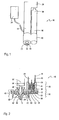
- a needless jet injector system with a separate reservoir for injecting a fluid medicament into the tissue of a patient in accordance with the present invention is represented in Fig. 1, and is generally designated 10.
- the system 10 includes a cassette device 12 which connects the jet injector 14 with the reservoir 16.
- An orifice 18 is formed in a tip 20, which is part of the cassette 12.
- An interface is created between the skin of a patient and the cassette 12 by a cassette/skin interface 22 formed in the cassette 12, and surrounding the tip 20.
- a control mechanism 26 is incorporated into the system 10 and interacts with the jet injector 14 and the reservoir 16 at an upper end 34 of the reservoir 16 to release a measured amount of a fluid medicament.
- the cassette 12 has an upper body 28 and a lower body 30.
- a fluid pathway 32 is formed at the interface between the upper body 28 and the lower body 30.
- the reservoir 16 also has a lower end 36, and attaches at the lower end 36 to the upper body 28.
- the fluid pathway 32 leads from an opening 38 at the lower end 36 of the reservoir 16 to an opening 40 in an impulse chamber 42.
- a spike 39 extends upward from the upper body 28 and into the reservoir 16 through the opening 38 at the lower end 36 of the reservoir 16. This spike 39 is formed with a longitudinal channel 41 which leads to the fluid pathway 32.
- a pre-filled cartridge 48 which has a rubber stopper 50 at a lower end 52, is placed in the reservoir 16.
- the rubber stopper 50 is pierced by the spike 39.
- the fluid medicament flows from the reservoir 16, through the channel 41 in the spike 39, along the fluid pathway 32, and into the impulse chamber 42.
- the impulse chamber 42 is formed in the cassette 12, and extends from the upper body 28 to the lower body 30.
- the lower body of the cassette 30 further forms a nozzle 44 that extends from the impulse chamber 42 and ends at the orifice 18 in the tip 20.
- the lower body 30 forms the cassette/skin interface 22.
- a vacuum system 46 creates suction between the cassette 12 and the skin of the patient at the interface 22, stabilizing the skin in preparation for an injection.
- the jet injector 14 also requires an impulse generator 54 to supply the energy needed to force a fluid medicament through the skin.
- a ram 56 extends from the impulse generator 54 and fits into a plunger 58 formed in the impulse chamber 42.
- the impulse generator 54 using stored energy, accelerates the ram 56, which strikes the plunger 58.
- the fluid medicament in the impulse chamber 42 is forced from the impulse chamber 42 through the nozzle 44 to the orifice 18 at the tip 20 and punctures the skin of the patient.
- the pressure created by the ram 56 as it impacts the plunger 58 creates pressure waves. These waves flow back through the fluid pathway 32 to the reservoir 16.
- Fig. 2 illustrates a preferred embodiment of a fluid pathway 32 which will attenuate the pressure waves.
- a tortuous fluid pathway 32 is formed with several right angles 60 between the reservoir 16 and the impulse chamber 42 to divert the pressure waves.
- another embodiment includes a flap 62 formed on the plunger 58.
- This flap 62 extends below the opening 40 of the fluid pathway 32 into the impulse chamber 42 when the plunger 58 is impacted by the ram 56. As a result, the fluid pathway 32 is blocked when pressure is exerted on the plunger 58.
- Fig. 4 shows an embodiment using a ball check valve 64 attached to a spring 66 which doses the opening 38 of the reservoir 16 in response to pressure exerted along the fluid pathway 32.
- Fig. 5 shows yet another embodiment with a flap valve 68 which isolates the reservoir 16 from the pressure waves created by the impact of the ram 56 on the plunger 58.
- Fig. 6 illustrates another embodiment in which the flap valve 68 and an elastomeric diaphragm 70 are molded of one piece.
- This embodiment includes a ridge 72 in the elastomeric material which surrounds the fluid pathway 32. The ridge 72 would be compressed by the pressure waves, sealing the fluid pathway 32.
- a system 10 for administering a full dose cartridge 48 shows the complete amount of the fluid medicament to be delivered in the impulse chamber 42.
- a valve 74 closes the fluid pathway 32.
- a movable stopper 76 is also shown, which is advanced by a lead screw 78.
- a single spring 80 is employed as the impulse generator 54 to inject the medication. It can be appreciated that a replaceable cap 81 is used to cover the tip 20 when the system 10 is not in use.
- Cross referencing Fig. 7 with Fig. 1 also shows the vacuum source 24.
- Fig. 8 shows an embodiment of the system 10 in which an encoder 82 is attached to a motor 84.
- the motor 84 advances the lead screw 78 to determine the amount of medication to be dispensed from the cartridge 48.
- the encoder 82 indicates when a driver 86 has advanced a rubber stopper 50 of the cartridge 48 the proper distance.
- Fig. 9 shows the system 10 being used with a multi-dose vial 88.
- a pump 90 is attached to tubing 92 which in turn attaches to the multi-dose vial 88 and to the upper body 28.
- Luer attachments 94 securely fasten the tubing 92 to the upper body 28.
- the pump 90 shuts off the flow of medication through the tubing 92, determining the amount of medication to be injected.
- Replaceable components of the lower body 30 are also illustrated. These include the tip 20 and the cassette/skin interface 22.
Landscapes
- Health & Medical Sciences (AREA)
- Vascular Medicine (AREA)
- Engineering & Computer Science (AREA)
- Anesthesiology (AREA)
- Biomedical Technology (AREA)
- Heart & Thoracic Surgery (AREA)
- Hematology (AREA)
- Life Sciences & Earth Sciences (AREA)
- Animal Behavior & Ethology (AREA)
- General Health & Medical Sciences (AREA)
- Public Health (AREA)
- Veterinary Medicine (AREA)
- Infusion, Injection, And Reservoir Apparatuses (AREA)
- External Artificial Organs (AREA)
Applications Claiming Priority (2)
| Application Number | Priority Date | Filing Date | Title |
|---|---|---|---|
| US892366 | 2001-06-26 | ||
| US09/892,366 US6652483B2 (en) | 2000-11-07 | 2001-06-26 | Needleless jet injector system with separate drug reservoir |
Publications (2)
| Publication Number | Publication Date |
|---|---|
| EP1277487A1 true EP1277487A1 (de) | 2003-01-22 |
| EP1277487B1 EP1277487B1 (de) | 2005-10-26 |
Family
ID=25399845
Family Applications (1)
| Application Number | Title | Priority Date | Filing Date |
|---|---|---|---|
| EP02077488A Expired - Lifetime EP1277487B1 (de) | 2001-06-26 | 2002-06-24 | Nadelloses Strahlinjektorsystem mit separatem Medikamentenbehälter |
Country Status (4)
| Country | Link |
|---|---|
| US (1) | US6652483B2 (de) |
| EP (1) | EP1277487B1 (de) |
| JP (1) | JP3816842B2 (de) |
| DE (1) | DE60206850T2 (de) |
Cited By (2)
| Publication number | Priority date | Publication date | Assignee | Title |
|---|---|---|---|---|
| US7988660B2 (en) | 2005-12-20 | 2011-08-02 | Eli Lilly And Company | Needle-free injection device |
| US8608684B2 (en) | 2003-11-27 | 2013-12-17 | Novo Nordisk A/S | Impulse chamber for jet delivery device |
Families Citing this family (40)
| Publication number | Priority date | Publication date | Assignee | Title |
|---|---|---|---|---|
| FR2809626B1 (fr) * | 2000-05-30 | 2003-03-07 | Poudres & Explosifs Ste Nale | Seringue sans aiguille avec membrane d'isolation d'un ejecteur multiconduit |
| US7217253B2 (en) * | 2001-06-26 | 2007-05-15 | Avant Medical Corp. | Sequential impulse/delivery fluid medicament injector |
| FR2834442B1 (fr) * | 2002-01-07 | 2004-10-08 | Saphir Medical | Appareil d'injection microdosee d'un produit actif par des jets de liquide de travail sous pression et procede de generation d'une sequence de jets liquides au moyen de cet appareil |
| WO2004101025A2 (en) * | 2003-05-09 | 2004-11-25 | Intravacc, Inc. | Needle free hypodermic injector and ampule for intradermal, subcutaneous and intramuscular injection |
| US6939319B1 (en) * | 2002-11-20 | 2005-09-06 | Conrad Anstead | Process and device for single use, needle-free intradermal, subcutaneous, or intramuscular injections |
| KR20060113730A (ko) * | 2003-12-18 | 2006-11-02 | 노보 노르디스크 에이/에스 | 피부 스트레칭 수단을 가진 노즐 장치 |
| JP4485878B2 (ja) * | 2003-12-26 | 2010-06-23 | 株式会社島津製作所 | 噴射式注射器 |
| US20060040895A1 (en) * | 2004-08-19 | 2006-02-23 | Kipling Thacker | Aesthetic use of hyaluronan |
| US8591457B2 (en) | 2005-08-10 | 2013-11-26 | Alza Corporation | Method for making a needle-free jet injection drug delivery device |
| CN101340940B (zh) | 2005-12-20 | 2012-07-18 | 诺沃-诺迪斯克有限公司 | 用于药物射流喷射单元的皮肤保持装置 |
| US7618396B2 (en) * | 2006-08-09 | 2009-11-17 | Avant Medical Corp. | Injection system with hidden needles |
| US7547293B2 (en) * | 2006-10-06 | 2009-06-16 | Bioject, Inc. | Triggering mechanism for needle-free injector |
| KR100799646B1 (ko) * | 2006-10-25 | 2008-01-30 | 한송욱 | 진공압을 이용한 바늘없는 주사기 |
| US7637889B2 (en) * | 2006-11-15 | 2009-12-29 | Glynntech, Inc. | Drug delivery device with sliding valve and methodology |
| US7935086B2 (en) * | 2006-12-14 | 2011-05-03 | L M M Global Innovations, Inc. | Multiple drug injection apparatus |
| WO2008103997A2 (en) | 2007-02-23 | 2008-08-28 | Bioject Inc. | Needle-free injection devices and drug delivery systems therefor |
| US9974904B2 (en) | 2008-05-20 | 2018-05-22 | Avant Medical Corp. | Autoinjector system |
| US8052645B2 (en) | 2008-07-23 | 2011-11-08 | Avant Medical Corp. | System and method for an injection using a syringe needle |
| US8177749B2 (en) | 2008-05-20 | 2012-05-15 | Avant Medical Corp. | Cassette for a hidden injection needle |
| ES2850948T3 (es) | 2008-12-09 | 2021-09-01 | Becton Dickinson Co | Sistema de administración de medicación de válvula abierta y cerrada para inyecciones de alta presión |
| EP2355862B1 (de) | 2008-12-09 | 2024-08-21 | Becton, Dickinson and Company | Zweikammer-arzneiausgabevorrichtung für hochdruckinjektionen |
| LT2699293T (lt) | 2011-04-20 | 2019-04-25 | Amgen Inc. | Automatinio purškimo prietaisas |
| US9408972B2 (en) * | 2011-08-02 | 2016-08-09 | Pharmajet, Inc. | Needle-free injection device |
| USD808010S1 (en) | 2012-04-20 | 2018-01-16 | Amgen Inc. | Injection device |
| USD898908S1 (en) | 2012-04-20 | 2020-10-13 | Amgen Inc. | Pharmaceutical product cassette for an injection device |
| WO2013190537A1 (en) | 2012-06-18 | 2013-12-27 | Michael Tavger | Method and system for delivering solution into the pores of recipient human skin |
| US10492990B2 (en) | 2013-03-15 | 2019-12-03 | Amgen Inc. | Drug cassette, autoinjector, and autoinjector system |
| US10092703B2 (en) | 2013-03-15 | 2018-10-09 | Amgen Inc. | Drug cassette, autoinjector, and autoinjector system |
| MX387880B (es) * | 2013-10-24 | 2025-03-19 | Univ Boston | Sistema de infusion para prevenir el uso del canal equivocado para la administracion de multiples medicamentos. |
| CN204033941U (zh) * | 2014-08-27 | 2014-12-24 | 北京快舒尔医疗技术有限公司 | 一种具有电动功能的无针注射器 |
| US10532158B2 (en) | 2014-10-09 | 2020-01-14 | Portal Instruments, Inc. | Fluid transfer mechanism for an injection device |
| CA2991058A1 (en) | 2015-07-08 | 2017-01-12 | Trustees Of Boston University | Infusion system and components thereof |
| WO2018129354A1 (en) | 2017-01-06 | 2018-07-12 | Trustees Of Boston University | Infusion system and components thereof |
| CN115243746B (zh) | 2019-07-16 | 2025-01-03 | 贝塔仿生公司 | 移动装置及其部件 |
| KR102165136B1 (ko) * | 2020-03-06 | 2020-10-13 | 바즈바이오메딕(주) | 무바늘 주사기 |
| US11278661B2 (en) | 2020-03-10 | 2022-03-22 | Beta Bionics, Inc. | Infusion system and components thereof |
| USD1031975S1 (en) | 2020-03-10 | 2024-06-18 | Beta Bionics, Inc. | Medicament infusion pump device |
| USD1099024S1 (en) | 2020-03-10 | 2025-10-21 | Beta Bionics, Inc. | Charging device for medicament infusion pump device |
| US11957542B2 (en) | 2020-04-30 | 2024-04-16 | Automed Patent Holdco, Llc | Sensing complete injection for animal injection device |
| WO2022056125A1 (en) * | 2020-09-09 | 2022-03-17 | The Trustees Of The University Of Pennsylvania | Needle-free injector, associated reloadable and disposable nozzles, and methods of injection |
Citations (5)
| Publication number | Priority date | Publication date | Assignee | Title |
|---|---|---|---|---|
| FR2339407A1 (fr) * | 1976-01-30 | 1977-08-26 | Merieux Inst | Injecteur de liquides a pression |
| US4059107A (en) * | 1975-05-08 | 1977-11-22 | Asahi Kasei Kogyo Kabushiki Kaisha | Two step type pressurized injector |
| EP0063341A1 (de) * | 1981-04-16 | 1982-10-27 | Hoechst Aktiengesellschaft | Kolbenpumpe für nadellose Injektionsgeräte |
| GB2309644A (en) * | 1995-05-22 | 1997-08-06 | Wolfgang Wagner | Device for diagnosis/therapy of a metabolic disturbance |
| WO1998013085A1 (en) * | 1996-09-26 | 1998-04-02 | Akzo Nobel N.V. | Needle-less injector |
Family Cites Families (4)
| Publication number | Priority date | Publication date | Assignee | Title |
|---|---|---|---|---|
| US5312335A (en) * | 1989-11-09 | 1994-05-17 | Bioject Inc. | Needleless hypodermic injection device |
| US5298023A (en) * | 1991-03-08 | 1994-03-29 | Habley Medical Technology Corporation | Multiple pharmaceutical dispenser with accumulator |
| US5383851A (en) * | 1992-07-24 | 1995-01-24 | Bioject Inc. | Needleless hypodermic injection device |
| US5993412A (en) * | 1997-05-19 | 1999-11-30 | Bioject, Inc. | Injection apparatus |
-
2001
- 2001-06-26 US US09/892,366 patent/US6652483B2/en not_active Expired - Fee Related
-
2002
- 2002-06-24 EP EP02077488A patent/EP1277487B1/de not_active Expired - Lifetime
- 2002-06-24 DE DE60206850T patent/DE60206850T2/de not_active Expired - Fee Related
- 2002-06-26 JP JP2002185404A patent/JP3816842B2/ja not_active Expired - Fee Related
Patent Citations (5)
| Publication number | Priority date | Publication date | Assignee | Title |
|---|---|---|---|---|
| US4059107A (en) * | 1975-05-08 | 1977-11-22 | Asahi Kasei Kogyo Kabushiki Kaisha | Two step type pressurized injector |
| FR2339407A1 (fr) * | 1976-01-30 | 1977-08-26 | Merieux Inst | Injecteur de liquides a pression |
| EP0063341A1 (de) * | 1981-04-16 | 1982-10-27 | Hoechst Aktiengesellschaft | Kolbenpumpe für nadellose Injektionsgeräte |
| GB2309644A (en) * | 1995-05-22 | 1997-08-06 | Wolfgang Wagner | Device for diagnosis/therapy of a metabolic disturbance |
| WO1998013085A1 (en) * | 1996-09-26 | 1998-04-02 | Akzo Nobel N.V. | Needle-less injector |
Cited By (2)
| Publication number | Priority date | Publication date | Assignee | Title |
|---|---|---|---|---|
| US8608684B2 (en) | 2003-11-27 | 2013-12-17 | Novo Nordisk A/S | Impulse chamber for jet delivery device |
| US7988660B2 (en) | 2005-12-20 | 2011-08-02 | Eli Lilly And Company | Needle-free injection device |
Also Published As
| Publication number | Publication date |
|---|---|
| US20020055707A1 (en) | 2002-05-09 |
| DE60206850T2 (de) | 2006-07-06 |
| DE60206850D1 (de) | 2005-12-01 |
| US6652483B2 (en) | 2003-11-25 |
| EP1277487B1 (de) | 2005-10-26 |
| JP3816842B2 (ja) | 2006-08-30 |
| JP2003052825A (ja) | 2003-02-25 |
Similar Documents
| Publication | Publication Date | Title |
|---|---|---|
| US6652483B2 (en) | Needleless jet injector system with separate drug reservoir | |
| US7217253B2 (en) | Sequential impulse/delivery fluid medicament injector | |
| EP1896099B1 (de) | Injektionsvorrichtung mit sekundärbehälter | |
| US20090105685A1 (en) | Two Stage Jet Injection Device | |
| US8608684B2 (en) | Impulse chamber for jet delivery device | |
| US6558348B2 (en) | Low cost disposable needleless injector system for variable and fixed dose applications | |
| JPH05184674A (ja) | 注射噴射器 | |
| AU2001251739A1 (en) | Low cost disposable needleless injector system for variable and fixed dose applications | |
| JP2007514489A (ja) | 皮膚引き伸ばし手段を有するノズルデバイス | |
| JP2018524096A (ja) | 単回使用送達デバイス | |
| JP6032892B2 (ja) | 皮内投与システムのためのカートリッジストッパー | |
| US20050165362A1 (en) | Injector with shielded needle | |
| EP2489379A1 (de) | Intradermaler Stiftadapter | |
| MX2023005062A (es) | Ensamblaje de dispositivo de administracion de farmacos y accesorio para dispositivo de administracion de farmacos. | |
| US20250288492A1 (en) | Vial adapter and injector assembly for a needle-free injector | |
| US20200108205A1 (en) | Ampule Autoinjector Systems and Methods | |
| WO2022197775A1 (en) | Non-axial safety syringe | |
| CN116437977A (zh) | 用于药物输送装置的流体转移系统 | |
| WO2005058392A2 (en) | Cartridge for delivery device |
Legal Events
| Date | Code | Title | Description |
|---|---|---|---|
| PUAI | Public reference made under article 153(3) epc to a published international application that has entered the european phase |
Free format text: ORIGINAL CODE: 0009012 |
|
| AK | Designated contracting states |
Kind code of ref document: A1 Designated state(s): AT BE CH CY DE DK ES FI FR GB GR IE IT LI LU MC NL PT SE TR |
|
| AX | Request for extension of the european patent |
Free format text: AL;LT;LV;MK;RO;SI |
|
| 17P | Request for examination filed |
Effective date: 20030702 |
|
| AKX | Designation fees paid |
Designated state(s): DE FR GB IT |
|
| 17Q | First examination report despatched |
Effective date: 20040810 |
|
| GRAP | Despatch of communication of intention to grant a patent |
Free format text: ORIGINAL CODE: EPIDOSNIGR1 |
|
| GRAS | Grant fee paid |
Free format text: ORIGINAL CODE: EPIDOSNIGR3 |
|
| GRAA | (expected) grant |
Free format text: ORIGINAL CODE: 0009210 |
|
| AK | Designated contracting states |
Kind code of ref document: B1 Designated state(s): DE FR GB IT |
|
| REG | Reference to a national code |
Ref country code: GB Ref legal event code: FG4D |
|
| REF | Corresponds to: |
Ref document number: 60206850 Country of ref document: DE Date of ref document: 20051201 Kind code of ref document: P |
|
| ET | Fr: translation filed | ||
| PLBE | No opposition filed within time limit |
Free format text: ORIGINAL CODE: 0009261 |
|
| STAA | Information on the status of an ep patent application or granted ep patent |
Free format text: STATUS: NO OPPOSITION FILED WITHIN TIME LIMIT |
|
| 26N | No opposition filed |
Effective date: 20060727 |
|
| PGFP | Annual fee paid to national office [announced via postgrant information from national office to epo] |
Ref country code: IT Payment date: 20081224 Year of fee payment: 7 |
|
| PGFP | Annual fee paid to national office [announced via postgrant information from national office to epo] |
Ref country code: DE Payment date: 20081230 Year of fee payment: 7 |
|
| PGFP | Annual fee paid to national office [announced via postgrant information from national office to epo] |
Ref country code: GB Payment date: 20081217 Year of fee payment: 7 |
|
| PGFP | Annual fee paid to national office [announced via postgrant information from national office to epo] |
Ref country code: FR Payment date: 20081231 Year of fee payment: 7 |
|
| GBPC | Gb: european patent ceased through non-payment of renewal fee |
Effective date: 20090624 |
|
| REG | Reference to a national code |
Ref country code: FR Ref legal event code: ST Effective date: 20100226 |
|
| PG25 | Lapsed in a contracting state [announced via postgrant information from national office to epo] |
Ref country code: FR Free format text: LAPSE BECAUSE OF NON-PAYMENT OF DUE FEES Effective date: 20090630 |
|
| PG25 | Lapsed in a contracting state [announced via postgrant information from national office to epo] |
Ref country code: GB Free format text: LAPSE BECAUSE OF NON-PAYMENT OF DUE FEES Effective date: 20090624 |
|
| PG25 | Lapsed in a contracting state [announced via postgrant information from national office to epo] |
Ref country code: DE Free format text: LAPSE BECAUSE OF NON-PAYMENT OF DUE FEES Effective date: 20100101 |
|
| PG25 | Lapsed in a contracting state [announced via postgrant information from national office to epo] |
Ref country code: IT Free format text: LAPSE BECAUSE OF NON-PAYMENT OF DUE FEES Effective date: 20090624 |