EP1277524A1 - Vidage de récipients métalliques sous pression avec canal de fluide situé à l'extérieur d'un outil - Google Patents
Vidage de récipients métalliques sous pression avec canal de fluide situé à l'extérieur d'un outil Download PDFInfo
- Publication number
- EP1277524A1 EP1277524A1 EP20010117453 EP01117453A EP1277524A1 EP 1277524 A1 EP1277524 A1 EP 1277524A1 EP 20010117453 EP20010117453 EP 20010117453 EP 01117453 A EP01117453 A EP 01117453A EP 1277524 A1 EP1277524 A1 EP 1277524A1
- Authority
- EP
- European Patent Office
- Prior art keywords
- tool
- opening
- wall
- shock absorber
- seal
- Prior art date
- Legal status (The legal status is an assumption and is not a legal conclusion. Google has not performed a legal analysis and makes no representation as to the accuracy of the status listed.)
- Withdrawn
Links
Images
Classifications
-
- F—MECHANICAL ENGINEERING; LIGHTING; HEATING; WEAPONS; BLASTING
- F16—ENGINEERING ELEMENTS AND UNITS; GENERAL MEASURES FOR PRODUCING AND MAINTAINING EFFECTIVE FUNCTIONING OF MACHINES OR INSTALLATIONS; THERMAL INSULATION IN GENERAL
- F16F—SPRINGS; SHOCK-ABSORBERS; MEANS FOR DAMPING VIBRATION
- F16F9/00—Springs, vibration-dampers, shock-absorbers, or similarly-constructed movement-dampers using a fluid or the equivalent as damping medium
- F16F9/32—Details
- F16F9/43—Filling or drainage arrangements, e.g. for supply of gas
- F16F9/437—Drainage arrangements
-
- B—PERFORMING OPERATIONS; TRANSPORTING
- B09—DISPOSAL OF SOLID WASTE; RECLAMATION OF CONTAMINATED SOIL
- B09B—DISPOSAL OF SOLID WASTE NOT OTHERWISE PROVIDED FOR
- B09B3/00—Destroying solid waste or transforming solid waste into something useful or harmless
- B09B3/30—Destroying solid waste or transforming solid waste into something useful or harmless involving mechanical treatment
- B09B3/35—Shredding, crushing or cutting
-
- F—MECHANICAL ENGINEERING; LIGHTING; HEATING; WEAPONS; BLASTING
- F17—STORING OR DISTRIBUTING GASES OR LIQUIDS
- F17C—VESSELS FOR CONTAINING OR STORING COMPRESSED, LIQUEFIED OR SOLIDIFIED GASES; FIXED-CAPACITY GAS-HOLDERS; FILLING VESSELS WITH, OR DISCHARGING FROM VESSELS, COMPRESSED, LIQUEFIED, OR SOLIDIFIED GASES
- F17C7/00—Methods or apparatus for discharging liquefied, solidified, or compressed gases from pressure vessels, not covered by another subclass
-
- B—PERFORMING OPERATIONS; TRANSPORTING
- B09—DISPOSAL OF SOLID WASTE; RECLAMATION OF CONTAMINATED SOIL
- B09B—DISPOSAL OF SOLID WASTE NOT OTHERWISE PROVIDED FOR
- B09B2101/00—Type of solid waste
- B09B2101/014—Shock absorbers, especially draining thereof
-
- B—PERFORMING OPERATIONS; TRANSPORTING
- B09—DISPOSAL OF SOLID WASTE; RECLAMATION OF CONTAMINATED SOIL
- B09B—DISPOSAL OF SOLID WASTE NOT OTHERWISE PROVIDED FOR
- B09B2101/00—Type of solid waste
- B09B2101/02—Gases or liquids enclosed in discarded articles, e.g. aerosol cans or cooling systems of refrigerators
-
- F—MECHANICAL ENGINEERING; LIGHTING; HEATING; WEAPONS; BLASTING
- F17—STORING OR DISTRIBUTING GASES OR LIQUIDS
- F17C—VESSELS FOR CONTAINING OR STORING COMPRESSED, LIQUEFIED OR SOLIDIFIED GASES; FIXED-CAPACITY GAS-HOLDERS; FILLING VESSELS WITH, OR DISCHARGING FROM VESSELS, COMPRESSED, LIQUEFIED, OR SOLIDIFIED GASES
- F17C2203/00—Vessel construction, in particular walls or details thereof
- F17C2203/06—Materials for walls or layers thereof; Properties or structures of walls or their materials
- F17C2203/0634—Materials for walls or layers thereof
- F17C2203/0636—Metals
-
- F—MECHANICAL ENGINEERING; LIGHTING; HEATING; WEAPONS; BLASTING
- F17—STORING OR DISTRIBUTING GASES OR LIQUIDS
- F17C—VESSELS FOR CONTAINING OR STORING COMPRESSED, LIQUEFIED OR SOLIDIFIED GASES; FIXED-CAPACITY GAS-HOLDERS; FILLING VESSELS WITH, OR DISCHARGING FROM VESSELS, COMPRESSED, LIQUEFIED, OR SOLIDIFIED GASES
- F17C2223/00—Handled fluid before transfer, i.e. state of fluid when stored in the vessel or before transfer from the vessel
- F17C2223/03—Handled fluid before transfer, i.e. state of fluid when stored in the vessel or before transfer from the vessel characterised by the pressure level
- F17C2223/035—High pressure (>10 bar)
-
- F—MECHANICAL ENGINEERING; LIGHTING; HEATING; WEAPONS; BLASTING
- F17—STORING OR DISTRIBUTING GASES OR LIQUIDS
- F17C—VESSELS FOR CONTAINING OR STORING COMPRESSED, LIQUEFIED OR SOLIDIFIED GASES; FIXED-CAPACITY GAS-HOLDERS; FILLING VESSELS WITH, OR DISCHARGING FROM VESSELS, COMPRESSED, LIQUEFIED, OR SOLIDIFIED GASES
- F17C2223/00—Handled fluid before transfer, i.e. state of fluid when stored in the vessel or before transfer from the vessel
- F17C2223/03—Handled fluid before transfer, i.e. state of fluid when stored in the vessel or before transfer from the vessel characterised by the pressure level
- F17C2223/036—Very high pressure (>80 bar)
-
- F—MECHANICAL ENGINEERING; LIGHTING; HEATING; WEAPONS; BLASTING
- F17—STORING OR DISTRIBUTING GASES OR LIQUIDS
- F17C—VESSELS FOR CONTAINING OR STORING COMPRESSED, LIQUEFIED OR SOLIDIFIED GASES; FIXED-CAPACITY GAS-HOLDERS; FILLING VESSELS WITH, OR DISCHARGING FROM VESSELS, COMPRESSED, LIQUEFIED, OR SOLIDIFIED GASES
- F17C2227/00—Transfer of fluids, i.e. method or means for transferring the fluid; Heat exchange with the fluid
- F17C2227/04—Methods for emptying or filling
-
- F—MECHANICAL ENGINEERING; LIGHTING; HEATING; WEAPONS; BLASTING
- F17—STORING OR DISTRIBUTING GASES OR LIQUIDS
- F17C—VESSELS FOR CONTAINING OR STORING COMPRESSED, LIQUEFIED OR SOLIDIFIED GASES; FIXED-CAPACITY GAS-HOLDERS; FILLING VESSELS WITH, OR DISCHARGING FROM VESSELS, COMPRESSED, LIQUEFIED, OR SOLIDIFIED GASES
- F17C2227/00—Transfer of fluids, i.e. method or means for transferring the fluid; Heat exchange with the fluid
- F17C2227/04—Methods for emptying or filling
- F17C2227/044—Methods for emptying or filling by purging
-
- F—MECHANICAL ENGINEERING; LIGHTING; HEATING; WEAPONS; BLASTING
- F17—STORING OR DISTRIBUTING GASES OR LIQUIDS
- F17C—VESSELS FOR CONTAINING OR STORING COMPRESSED, LIQUEFIED OR SOLIDIFIED GASES; FIXED-CAPACITY GAS-HOLDERS; FILLING VESSELS WITH, OR DISCHARGING FROM VESSELS, COMPRESSED, LIQUEFIED, OR SOLIDIFIED GASES
- F17C2260/00—Purposes of gas storage and gas handling
- F17C2260/03—Dealing with losses
- F17C2260/035—Dealing with losses of fluid
- F17C2260/036—Avoiding leaks
Definitions
- the invention relates to a method and a device for opening and emptying of pressure metal containers for fluids.
- the invention focuses primarily on the opening and emptying of shock absorbers, such as those of road vehicles.
- shock absorbers contain a shock absorber oil, which because of its flammability and of environmental hazards it should be disposed of if a shock absorber has reached the end of its life. For this, the shock absorber oil has to go through the relatively solid metal walls of the shock absorber are drained through can. This problem occurs mainly in small and medium-sized companies such as Scrap yards and auto repair shops to a considerable extent.
- the cited document also suggests a tool with a pointed round cone shape to be used with a careful and slow Pressing into the shock absorber wall against an essentially sealing system can form the shock absorber wall. Then the shock absorber oil through the Tool can be drained through, so that an outer seal is unnecessary. In this way, the surface contaminated by the shock absorber oil can also be minimized.
- the present invention is based on the described state of the Technology based on the problem, a method for a device for opening and Emptying pressure metal containers to indicate the state of the art Technology offers improved opportunities.
- the invention is directed to a method for opening and emptying Pressurized metal containers for fluids, with a tip or cutting edge having tool an opening in a wall of the pressure metal container is pressed, characterized in that one when emptying the Pressure metal container surrounding the tool and sealing against the wall of the Pressure metal container adjacent elastic seal is provided and while the tool is in the opening in the wall, between the opening and a first area of an outer surface of the tool and between the Seal and a second area adjoining the first area A channel is formed on the outer surface of the tool, through which the fluid passes is discharged from the pressure metal container, as well as on a corresponding designed device.
- the present invention is based on the following idea: If, as in the cited application suggested the tool itself or its attachment to the Container wall used as a seal for the fluid and consequently to a separate seal completely dispensed with, so you will according to this state of the Technique the fluid out of the container through a channel in the tool to lead. Alternatively, you could also use the tool after opening the opening Pull it all the way out, opening the opening and then removing the fluid from the to allow free opening to emerge.
- the present invention takes a different approach by proposing leave the tool in the opening when emptying the pressure metal container, but also a surrounding and a sealing system to the tool To use a separate seal producing the pressure metal container wall. Then can the tool remains in the opening, but a channel between one The outer surface of the tool remains free in the area of the opening and the opening, through which the fluid can escape. The fluid then continues to flow within the Seal, i.e. between the outer surface of the tool and the seal.
- the Outer surface of the tool specifically a first area in the Area of the opening of the pressure metal container wall and a second area, the connected to it outside the pressure metal container, on the one hand and on the other the opening in the pressure metal container wall and the seal thus define one Drain channel for the fluid. This allows one to lie within the tool Inner channel can be dispensed with or at least supplemented with such an inner channel become.
- the advantage of the tool remaining in the opening is that in addition to stabilizing and slipping of the device to avoid compared to the pressure metal container.
- a certain force is necessary against the pressure metal container wall, on the other hand possibly due to the lubricating properties of the fluid is relatively slippery, this aspect can play an essential role in that Play reliability and control of the process. It is too take into account that slipping inevitably leads to uncontrolled Leakage of the fluid and thus endanger the personnel or the environment would lead. This applies in particular to mobile use, which means that the Device or part of the device moved by hand and on one Shock absorber or the like is used in the installed state.
- the replacement of an internal channel in the tool or the addition of such a channel through the above-described channel along the outer surface is the cross-sectional area for the passage of the fluid to enlarge.
- internal channels are in limited to the tool because the stability of the tool, especially in Area of the front surfaces finally pressing on the pressure metal container wall large channels or large channel openings would be restricted.
- the invention offers thus the possibility of discharging the fluid faster than in the cited state of the Technology.
- the speed of emptying the fluid also accommodates that the tool can remain in the opening when emptying.
- the emptying can So start immediately when the tool opens in the Has produced pressure metal tank wall. It doesn't have to be withdrawn first in particular, there is no need for another seal, for example with a Suction line could be connected after withdrawing the tool be put on.
- this invention too preferably, the tool evenly and slowly into the pressure metal container wall push in. It should preferably neither be hammered in nor hammered in, still be shot to the possible by shock loads to prevent uncontrolled deformation and cracking of the wall. Have this namely even if there is an additional seal surrounding the tool is provided, the disadvantage of an uncontrolled escape of the fluid at least in To enable individual cases, such as when such a crack over the seal covered area of the wall of the pressure metal container goes out or this wall due to an uncontrolled bending no longer for a sealing Installation of the seal is suitable.
- the slow and even pressing is again preferably done with a Hydraulic cylinder accomplished.
- a Hydraulic pump are supplied, which in turn is pneumatically operated.
- Pneumatic supplies, especially compressed air, are in fact the case with most Eligible workshops already exist.
- pneumatically operated hydraulic pump when handling flammable fluids safer than an electric pump or an internal combustion engine.
- it can also an electrical supply to the hydraulic pump can be selected if this Aspects should be immaterial.
- the channel where it is bounded by the opening in the pressure metal container wall is various ways.
- the tool could only be a little bit after being pressed on withdrawn to expose a gap. This slight withdrawal does not lead to a significant time delay nor does the safety function of the tool in the opening is significantly impaired.
- the tool in the Claims designated as the first area of the outer surface, ie where the channel is formed together with the opening of the pressure metal container wall, not to be rotationally symmetrical, for example angular. If the tool then if something is twisted after being pressed on, gaps necessarily arise between this area of the tool outer surface and the pressure metal container wall.
- the outer surface of the tool can at least in the have so-called first area grooves for the discharge of the fluid, ie in be concave in any way.
- These grooves can, for example simple milling grooves in the outer surface.
- These grooves preferably settle also in the so-called second area of the outer surface and support that Leakage of fluid also in the area of the channel that is outside of the seal is limited.
- the tool itself to give changing cross-sectional profile profile along the direction of the pressing.
- the direction of the push-on of the Axial direction of the tool spoken, although this tool is neither necessarily rotate must still be rotationally symmetrical.
- the change the cross-sectional profile along the axial direction the cross-section perpendicular to the axial direction is meant to be done so that first with a first shape of the profile the beginning of the opening is created and a crack pattern in the pressure metal tank wall is created.
- This crack pattern is noted not uncontrolled, but essentially on the area of intrusion of the Tool limited, in any case does not go as far as that through the seal detected area beyond that the problems described arise would.
- the tool If the tool is pushed further into the wall, expand it the opening further out. Especially if it has an angular first profile shape is used, the corners of which can form cutting the tool advantageously a completely chip-free controlled peeling of the wall inwards are caused, whereby the inwardly bending wall parts by cracks or dividing lines caused by these cutting edges separated are. So there is the pattern of the cracks (with “cracks” “cutting lines” with includes) embossed by the first profile shape.
- the first profile shape can be triangular or square, for example, the second Profile shape should either have a larger number of corners and / or be more convex be designed, i.e. have surfaces that are rounded outwards between the corners, and / or round (circular or elliptical or similar).
- the more convex or Round profile sections then press the metal parts described between the Cracks continue radially outward (radial in the sense of perpendicular to the axial direction of the tool) and peel them into the interior of the pressure metal container. Gaps for the fluid channel then arise in the area of the cracks.
- an inner channel can be provided in the tool.
- the invention does not exclude an internal channel for the fluid but supplements it this may just be.
- one could alternatively or additionally Inner channel included in the tool for pressure equalization in the Pressure metal container is used. This can support the drainage of the fluid, as soon as the internal overpressure of the pressure metal container is reduced.
- an inner channel also for pressurizing the interior of the Pressurized metal container serve to accelerate the emptying. For example compressed air could be injected into a shock absorber so that the shock absorber oil can be removed relatively quickly.
- a mobile device which is considered mobile, is preferred Unit has a hand-movable device part, which by a Operator installed under a vehicle, for example Shock absorbers can be used.
- This mobile part can be replaced by a Pressurized fluid line can be supplied by an escort car, for example by the Hydraulic pump is included.
- the escort can stand next to the vehicle stay and does not hinder the user.
- the mobile part can be a preferably have hook-shaped abutments to counteract the force Pushing the tool into the shock absorber and secure it To allow anchoring.
- a seal is also provided which is at least partially made a PU material.
- the invention is based on the idea that the use of a Elastic seal surrounding the tool for emptying at the tool Tool outer surface along initially necessary, but also for other reasons can be beneficial. On the one hand, it can e.g. with gaseous fluids or very low viscosity fluids may be insufficient, relying solely on a sealing system between the tool and the pressure metal container wall. To the the second can be used in the case of the one already cited in the earlier Registration described and also preferred here mobile use of the Device possible tilting of a mobile part or handheld device the shock absorber leaks between opening and emptying Tool and pressure metal container wall occur.
- a particularly suitable sealing material is that already mentioned Polyurethane material (PU material), which is tested by the inventor has proven extremely successful.
- PU material Polyurethane material
- the PU materials have mainly been compared to chemical or mechanical Stress proven to be very long-lasting and achieved in practical use long lifetimes. The inventors are aware of the use of such PU materials not known for seals of this type. Rather, it is especially around materials previously used for soles of sports shoes were.
- the PU material used is an inexpensive one Has permanent bending behavior. This is a requirement, especially when Shoe sole materials are met. It is not sufficient if the seal according to the invention required only at the beginning of their use Has properties. Rather, it must remain unchanged even after frequent use can do their job. When disposing of the contents of Pressure metal containers, especially shock absorber oil, the seals in in practice, however, extremely frequently due to deformations and compressions claimed, so that the permanent bending behavior, similar to Shoe sole materials, special emphasis should be placed. It has proven itself to demand a value of at least 50,000, preferably more than 70,000. This permanent bending behavior is defined by DIN 53543.
- the multi-component nature of course relates to that Manufacturing process of the seal.
- the seal itself will be in use normally be in one piece and consist of a continuous material. This is however not absolutely necessary, it could also be multi-part and / or seals composed of several materials are used. there The statements in this description relate to at least part of the Seal, especially on that for elastic deformation and adaptation to the Pressure metal tank wall responsible part.
- the use of multi-component Systems has the advantage of greater flexibility compared to one-component systems and a relatively short curing time during production and thus leads to more practical processes and less expensive seals.
- polyether PU materials have proven themselves, albeit also Polyester materials come into question.
- the polyether materials can be used in the Usually process at lower temperatures, especially in the vicinity of the Room temperature, which in turn is a simple and therefore inexpensive Manufacturing process accommodates.
- it can be a act two-component polyether PU material system, in which one Component a mixture of polyols, activators, stabilizers and blowing agents and the other component is a mixture with diphenyl methane diisocyanate.
- one Component a mixture of polyols, activators, stabilizers and blowing agents and the other component is a mixture with diphenyl methane diisocyanate.
- Particularly preferred is that sold under the trade name Elastopan Material S 7588/100 from Elastrogran GmbH, 82133 Olching.
- the PU material according to the invention is is a casting elastomer, which is a simple casting process to the Seal can be shed. This requirement is mentioned by the Elastopan material fulfilled.
- the elastopan material is essentially transparent after curing.
- a More transparent seal is also preferred for the invention, because that is Emptying the pressure metal container can be checked visually.
- the visual Control can relate to the application and pressing in of the tool and also include leakage of the fluid and its end.
- seals not only have the advantage of simpler construction, but also shows the leakage and the end of the leakage of the fluid earlier on. In addition, as already stated, the position can only be determined by the seal actually check the tool against the pressure vessel wall.
- the exemplary embodiment illustrates an advantageous shape for the seal
- the following aspects are essential:
- First is basically preferred that the seal have a substantially cylindrical shape has, with the cylinder on the side facing away from the container except for one Passage opening for the tool can be closed and on the container-facing side may be tapered.
- the walls of the Cylindrical shape are preferably bellows-like, ie parallel in one cut wave-like to the tool axis, designed. So they can be particularly cheap push together by the edges of the bellows shape or waveform be kinked.
- the seal can be in the relaxed state up to protrude the front of the tool and fully protect it and cover and prevent oil from dripping from the tool onto the floor.
- the tool can be inserted deep into the pressure metal container without that the seal significantly impedes this movement.
- the side of the seal facing the pressure metal container is facing inwards has inclined walls, such as a conical shape or also a shape tapered inwards in any way, so in addition to the inherent stability of the sealing walls, that avoided initially fluid escaping under pressure pushes the seal apart in this area and can escape between the pressure metal container and the seal.
- the container-facing Side of the seal in a particularly simple manner directly between one formed by the tool collar or the like and one on the Clamping contact surface provided on the side facing away from the pressure metal container be kept.
- the seal only has to be on an assembly shaft of the tool and is automatically held when that Tool is inserted and attached.
- the contact surface on the The side facing away from the pressure metal container can preferably be designed on the outside be that it grips the seal a little to prevent it Prevent the seal from pressing against the container.
- the Seal beveled in this area and the contact surface for this be complementary.
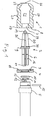
- Figure 1 shows the details of the parts essential to the invention Device for opening and emptying a shock absorber of a car or truck.
- a seal 1 is drawn in on the left, a tool 2 in the middle, on the right thereof a mounting surface 3 for the seal 1 having mounting washer 4 and to the right of it a piston rod 5 together with small parts for fastening the Tool.
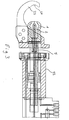
- Figure 3 shows the parts in the assembled state, with the additional Details in Figure 3 will be discussed below.
- Tool 2 with a tool shaft 6 through an opening 7 in a (not Shown) end wall 8 facing away from the shock absorber can and with a collar 9 on the wall 8, namely on its inside, which as a result the opening 7 forms an approach, strikes.
- the shaft 6 of the tool 2 then protrudes beyond the wall 8 of the seal 1 and can be passed through a central opening in the mounting disc 4 and via a sealing O-ring 10 into a receptacle 12 of the Piston rod 5 are inserted.
- the receptacle 12 has one in the channel 14 Connection 13 to be inserted axially and centrally in the tool 2 extending inner channel 14, in the detailed representations in Figure 2, the are explained in more detail below, can also be clearly seen in cross section.
- the connection 13 is inserted into the channel 14, as shown in FIG. 3.
- the tool shaft 6 can then be in the receptacle 12 of the piston rod 5 with the help a locking pin 15 are locked in a groove 16 on the Tool shaft 6 engages.
- Figure 3 illustrates that the collar 9 then the seal 1 to the contact surface 3 of the Press mounting plate 4.
- the mounting plate 4 faces End wall 8 of the seal 1 chamfered on the outside in a region 17, the Contact surface 3 of the mounting plate 4 complementary chamfered outer walls having. These areas are designated by 18. If the seal 1 in the Figures in the horizontal direction is strongly compressed, i.e. from left to right is pushed back, the bevels 17 and 18 prevent a lateral Break out seal 1 on mounting plate 4.
- the chamfer is less than 45 ° the neighboring areas.
- the side of the tool 2 facing away from the shaft 6, that is to say in the figures the left side consists essentially of an area 19 with a first Profile shape and a second area 20 with a second profile shape. These areas 19 and 20 of tool 2 are in the assembled state with the seal relaxed 1 within a formed by the seal and in the axial direction to the Shock absorber open cavity 21 of the seal 1.
- Figure 3 shows that the piston rod 5 is driven by a hydraulic cylinder 22 which is not explained in more detail here.
- Hydraulic cylinder 22 and the mobile unit containing it device according to the invention and the escort that this mobile unit with Hydraulic oil is supplied and the emptied shock absorber oil is collected on the input cited earlier patent application EP 00 105 684.5.
- the one there Description applies to the details of the tool 2 and the seal 1 here too.
- the escort contains a pneumatically operated hydraulic pump and is in turn connected to the compressed air supply via a compressed air line Workshop connected.
- FIG. 3 also shows one in FIG illustrated manner with the fixed parts of the hydraulic cylinder 22 connected hook 23, which has a bulge 24 for shock absorbers and Recording the same serves. It forms an abutment for pressing on Shock absorber.
- shock absorber in the receptacle 24 of the hook 23, it can Tool 2 using the piston rod 5 of the hydraulic cylinder 22 to the front be driven, at least up to the front tip of the plant Tool 2 on the shock absorber wall is done slowly and in a controlled manner. Before that front tip of the tool 2 reaches the shock absorber wall, that forms the Shock absorber facing end of the seal 1, which in the designated 25 Area converges obliquely inward at approximately 45 ° to form an opening 26, one sealing system on the shock absorber wall. The opening is limited 26 on the shock absorber wall.
- the seal 1 in a bellows designed side wall region 27 compressed and in its horizontal Extent (in the sense of the figures, not necessarily in the sense of use) pressed together.
- the front area 19 of the tool 2 begin to punch a hole in the shock absorber wall.
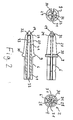
- the top right illustration in FIG. 2 shows a front view of the Tool 2.
- the front area 19 of the tool 2 square prismatic design.
- the four cutting edges are 28 in FIG designated.
- This prismatic section 19 cuts the first, so to speak Part of the opening in the shock absorber wall and thus defines the edges 28 corresponding cracks or cut lines in the shock absorber wall, the Bend metal wall parts between the edges 28 into the interior of the shock absorber or roll up.
- the shock absorber wall is peeled, so to speak.
- this prismatic shape changes into a cross section Axis direction circular cross-sectional shape above, the profile of the tool 2 rises less steeply in this rear area 20 than in the front area 19.
- the increase takes place from a first one, designated 29 in FIGS. 1 and 2 Circumference up to a second circumference 30.
- the now much more convex profile shape of area 20 presses the metal tabs further radially between the cracks or cutting lines corresponding to the edges 28 to the outside or inside the shock absorber.
- the rags tear in a controlled manner So far apart that the tear lines opposite the respective circular outer circumference of the area 20 of the tool 2 to the Release angular positions of the edges 28 and slots in their vicinity. By These slots allow the shock absorber oil to pass through the opening in the shock absorber wall and through the opening 26 of the seal 1 and through the interior 21 of the seal emerge from the shock absorber.
- This leakage is further caused by two axially extending at 180 ° to each other the tool 2 attached milling grooves 31 supported, which extend from a front Section of the area 19 of the workpiece 2 over the entire axial extent of the workpiece 2 to its opposite end.
- the milling grooves 31 allow in particular the passage of the shock absorber oil by the other end flush with the shank 6 of the tool 2 Opening 7 of the seal 1 and transport the shock absorber oil within the Piston rod 5 further. There it is not discussed here by anyone Oil drain channel continued to a hose line and from this to one Collection tank brought in the escort.
- FIG. 2 also shows one in the front area 19 in this lower illustration of the tool 2 with two lateral openings 32 ending inner channel 33, the can also be seen in the two representations at the top left and right in FIG.
- the illustration on the top left corresponds to a cross section transverse to Axis direction in the area of the federal government 9.
- This inner channel 33 with the openings 32 can be used to ventilate the inside of the shock absorber Pressure equalization after reducing the internal pressure of the shock absorber.
- the exemplary embodiment is additionally used to actively pressurize compressed air into the Blowing in shock absorbers, namely on a signal transmitted by the push button Operator to look after after the first shock oil surge has dried up the remaining shock absorber oil accelerates under pressure when the shock absorber is opened drive out of the shock absorber.
- the Openings 32 are relatively wide after the openings of the shock absorber wall have been made are inside the shock absorber interior, so the shock absorber wall long ago rear area 20 of the tool 2 is arranged.
- the seal 1 is below with further penetration of the Tool 2 increasing axial pressure on the shock absorber wall, where the conical shape of the front wall sections 25 ensures that the under Pressure escaping shock absorber oil that does not bend apart the rather soft seal and exits.
- the relatively soft design of the seal 1 is for this responsible that the front area, i.e. the border of the opening 26 the direction 1, completely and fitting to the curved shock absorber wall can nestle.
- this material like other PU materials with appropriate adjustment of the softness, basically an excellent Compromise between elasticity, extensibility and fatigue behavior. Despite its stability and durability, it is relatively soft. With this The material is originally intended for sports shoe soles PU material.
- this PU material is pourable and essentially as a casting transparent.
- the transparency allows you to look at the fully assembled device Figure 3 through the seal 1 through the process of pressing Visually inspect the shock absorber wall and the emptying of the shock absorber oil and watch. So you can see immediately when the The pressing process runs irregularly, when the first shock absorber oil comes and when Shock absorber oil no longer leaks, so that the compressed air flows through the inner channel 33 should be blown.
- the seal 1 is made by low pressure casting in a three-part aluminum mold produced, the surface of the wall 8 facing the piston rod 5 preferably forms the top. There are due to the relatively large area to the contact surface 3 of the mounting washer 4 lower demands on the Given surface quality. This system must also seal.
- the Low pressure casting can take place at a temperature in the range of 25 - 30 ° C and requires a curing time of only about 5 minutes. In order to is an inexpensive production in a technically particularly simple and fast manner of the seals 1, which is a wearing part of the invention Represent device.
- the invention offers an extremely valuable one in practice Possibility to dispose of shock absorbers in a simple and effective manner Drain shock absorber oil.
- the device according to the invention can be moved and in particular by hand under a vehicle on the shock absorber still installed.
- any conventional shock absorber to be opened without that they are provided with a specially designed for this form of disposal Vulnerability or wall thinning should be provided. Finally, the Opening the shock absorber wall on the one hand so carefully and gently that it is practical no shock oil escapes outside the seal 1 and on the other hand no chips arise, the drainage of the oil through the various channels and lines would hinder.
Landscapes
- Engineering & Computer Science (AREA)
- General Engineering & Computer Science (AREA)
- Environmental & Geological Engineering (AREA)
- Mechanical Engineering (AREA)
- Pressure Vessels And Lids Thereof (AREA)
Priority Applications (1)
| Application Number | Priority Date | Filing Date | Title |
|---|---|---|---|
| EP20010117453 EP1277524A1 (fr) | 2001-07-19 | 2001-07-19 | Vidage de récipients métalliques sous pression avec canal de fluide situé à l'extérieur d'un outil |
Applications Claiming Priority (1)
| Application Number | Priority Date | Filing Date | Title |
|---|---|---|---|
| EP20010117453 EP1277524A1 (fr) | 2001-07-19 | 2001-07-19 | Vidage de récipients métalliques sous pression avec canal de fluide situé à l'extérieur d'un outil |
Publications (1)
| Publication Number | Publication Date |
|---|---|
| EP1277524A1 true EP1277524A1 (fr) | 2003-01-22 |
Family
ID=8178075
Family Applications (1)
| Application Number | Title | Priority Date | Filing Date |
|---|---|---|---|
| EP20010117453 Withdrawn EP1277524A1 (fr) | 2001-07-19 | 2001-07-19 | Vidage de récipients métalliques sous pression avec canal de fluide situé à l'extérieur d'un outil |
Country Status (1)
| Country | Link |
|---|---|
| EP (1) | EP1277524A1 (fr) |
Citations (8)
| Publication number | Priority date | Publication date | Assignee | Title |
|---|---|---|---|---|
| EP0105684A1 (fr) | 1982-09-26 | 1984-04-18 | Sanden Corporation | Compresseur de réfrigérant à volutes avec mécanisme de volutes |
| EP0418946A1 (fr) * | 1989-08-25 | 1991-03-27 | Geert Hermannus Leemput | Appareil de prélèvement d'un fluide à travers une paroi |
| FR2696436A1 (fr) * | 1992-10-01 | 1994-04-08 | Armines | Procédé et dispositif de perforation d'un réservoir. |
| DE4340005A1 (de) * | 1992-12-07 | 1994-06-09 | Volkswagen Ag | Vorrichtung zum Entleeren eines flüssigkeitsgefüllten Gehäuses |
| DE29616266U1 (de) * | 1996-09-11 | 1996-11-21 | Lindner, Anton, 83131 Nußdorf | Vorrichtung zur Entnahme von Flüssigkeiten aus einem Flüssigkeitsbehälter, insbesondere eine Tankanbohrvorrichtung |
| EP0794020A2 (fr) * | 1996-03-09 | 1997-09-10 | Weisshaar, Angelika | Dispositif pour vider des conteneurs fermés, en particulier des filtres à carburant |
| FR2759317A1 (fr) * | 1997-02-10 | 1998-08-14 | Renault | Dispositif de recuperation du carburant contenu dans un reservoir de vehicule automobile |
| EP1036604A2 (fr) * | 1999-03-17 | 2000-09-20 | Maschinenbau Eggerstorfer GmbH | Vidage de récipients sous pression pour fluides |
-
2001
- 2001-07-19 EP EP20010117453 patent/EP1277524A1/fr not_active Withdrawn
Patent Citations (8)
| Publication number | Priority date | Publication date | Assignee | Title |
|---|---|---|---|---|
| EP0105684A1 (fr) | 1982-09-26 | 1984-04-18 | Sanden Corporation | Compresseur de réfrigérant à volutes avec mécanisme de volutes |
| EP0418946A1 (fr) * | 1989-08-25 | 1991-03-27 | Geert Hermannus Leemput | Appareil de prélèvement d'un fluide à travers une paroi |
| FR2696436A1 (fr) * | 1992-10-01 | 1994-04-08 | Armines | Procédé et dispositif de perforation d'un réservoir. |
| DE4340005A1 (de) * | 1992-12-07 | 1994-06-09 | Volkswagen Ag | Vorrichtung zum Entleeren eines flüssigkeitsgefüllten Gehäuses |
| EP0794020A2 (fr) * | 1996-03-09 | 1997-09-10 | Weisshaar, Angelika | Dispositif pour vider des conteneurs fermés, en particulier des filtres à carburant |
| DE29616266U1 (de) * | 1996-09-11 | 1996-11-21 | Lindner, Anton, 83131 Nußdorf | Vorrichtung zur Entnahme von Flüssigkeiten aus einem Flüssigkeitsbehälter, insbesondere eine Tankanbohrvorrichtung |
| FR2759317A1 (fr) * | 1997-02-10 | 1998-08-14 | Renault | Dispositif de recuperation du carburant contenu dans un reservoir de vehicule automobile |
| EP1036604A2 (fr) * | 1999-03-17 | 2000-09-20 | Maschinenbau Eggerstorfer GmbH | Vidage de récipients sous pression pour fluides |
Non-Patent Citations (1)
| Title |
|---|
| EP00105684 * |
Similar Documents
| Publication | Publication Date | Title |
|---|---|---|
| DE69402090T2 (de) | Spanneinrichtung | |
| EP2924322B1 (fr) | Dispositif d'étanchéité | |
| DE19915022A1 (de) | Elastomerdichtung zwischen einem Kolben und einem Zylinder und/oder einem Schaft eines automatischen Kraftfahrzeuggetriebes | |
| EP2176554B1 (fr) | Dispositif de sécurité pour récipient contenant des fluides sous pression | |
| EP3249374A1 (fr) | Dispositif de contrôle de pression | |
| EP1179149B1 (fr) | Dispositif d'etancheite pour un piston soumis a l'action d'un fluide sous pression dans un cylindre de travail | |
| DE1475683A1 (de) | Kupplungsdichtring | |
| DE3415627A1 (de) | Rohrpruefgeraet | |
| DE1259816B (de) | Kolben fuer hydraulische Grubenstempel od. dgl. | |
| DE60205087T2 (de) | Methode und kolben-zylinder-vorrichtung | |
| DE19816253A1 (de) | Rohrstopfen mit Sicherungsring | |
| EP1279449B1 (fr) | Méthode pour joindre deux objets | |
| EP3021997B1 (fr) | Dispositif de correction de surface d'étanchéité pour bouchons filetés, et système et procédé | |
| EP3583323B1 (fr) | Soufflet d'étanchéité pour une articulation à rotule et articulation à rotule équipée d'un tel soufflet d'étanchéité | |
| DE10314533A1 (de) | Dichtungsanordnung | |
| EP3344431B1 (fr) | Unité à fluide sous pression comportant un boîtier en plastique fabriqué par moulage par injection et procédé pour sa fabrication | |
| EP1283968A1 (fr) | Systeme d'etancheite pour tubes-guides | |
| EP1277525A1 (fr) | Dispositif pour le vidage de récipients métalliques sous pression avec élément d'étanchéité autour d'un outil | |
| DE20111797U1 (de) | Entleeren von Druckmetallbehältern für Fluide mit außerhalb eines Werkzeugs liegendem Fluidkanal | |
| DE20111796U1 (de) | Vorrichtung zum Entleeren von Druckmetallbehältern für Fluide mit ein Werkzeug umgebender Dichtung | |
| DE102014221576A1 (de) | Druckzylinder zur hydraulischen Steuerung von Anbaugeräten an Arbeitsfahrzeugen und hydraulisches Steuerungssystem für Anbaugeräte an Arbeitsfahrzeugen mit derartigen Druckzylindern | |
| DE69915321T2 (de) | Vorrichtung und verfahren für eine hochdruckpresse | |
| DE102015204799A1 (de) | Dichtungsvorrichtung | |
| DE10029305A1 (de) | Dichtungsvorrichtung für einen mit Druckmittel beaufschlagten Kolben in einem Arbeitszylinder | |
| DE19509162A1 (de) | Spritzschutz mit asymmetrischem Elastomer-Verschlußelement |
Legal Events
| Date | Code | Title | Description |
|---|---|---|---|
| PUAI | Public reference made under article 153(3) epc to a published international application that has entered the european phase |
Free format text: ORIGINAL CODE: 0009012 |
|
| AK | Designated contracting states |
Kind code of ref document: A1 Designated state(s): AT BE CH CY DE DK ES FI FR GB GR IE IT LI LU MC NL PT SE TR |
|
| AX | Request for extension of the european patent |
Free format text: AL;LT;LV;MK;RO;SI |
|
| 17P | Request for examination filed |
Effective date: 20030718 |
|
| AKX | Designation fees paid |
Designated state(s): AT BE CH CY DE DK ES FI FR GB GR IE IT LI LU MC NL PT SE TR |
|
| STAA | Information on the status of an ep patent application or granted ep patent |
Free format text: STATUS: THE APPLICATION IS DEEMED TO BE WITHDRAWN |
|
| 18D | Application deemed to be withdrawn |
Effective date: 20050201 |