EP1277538B1 - Fil à âme de flux pour le soudage - Google Patents
Fil à âme de flux pour le soudage Download PDFInfo
- Publication number
- EP1277538B1 EP1277538B1 EP02255053A EP02255053A EP1277538B1 EP 1277538 B1 EP1277538 B1 EP 1277538B1 EP 02255053 A EP02255053 A EP 02255053A EP 02255053 A EP02255053 A EP 02255053A EP 1277538 B1 EP1277538 B1 EP 1277538B1
- Authority
- EP
- European Patent Office
- Prior art keywords
- flux
- weight
- outer layer
- welding wire
- core wire
- Prior art date
- Legal status (The legal status is an assumption and is not a legal conclusion. Google has not performed a legal analysis and makes no representation as to the accuracy of the status listed.)
- Expired - Lifetime
Links
Images



Classifications
-
- B—PERFORMING OPERATIONS; TRANSPORTING
- B23—MACHINE TOOLS; METAL-WORKING NOT OTHERWISE PROVIDED FOR
- B23K—SOLDERING OR UNSOLDERING; WELDING; CLADDING OR PLATING BY SOLDERING OR WELDING; CUTTING BY APPLYING HEAT LOCALLY, e.g. FLAME CUTTING; WORKING BY LASER BEAM
- B23K35/00—Rods, electrodes, materials, or media, for use in soldering, welding, or cutting
- B23K35/22—Rods, electrodes, materials, or media, for use in soldering, welding, or cutting characterised by the composition or nature of the material
- B23K35/24—Selection of soldering or welding materials proper
- B23K35/30—Selection of soldering or welding materials proper with the principal constituent melting at less than 1550°C
- B23K35/3033—Ni as the principal constituent
-
- B—PERFORMING OPERATIONS; TRANSPORTING
- B23—MACHINE TOOLS; METAL-WORKING NOT OTHERWISE PROVIDED FOR
- B23K—SOLDERING OR UNSOLDERING; WELDING; CLADDING OR PLATING BY SOLDERING OR WELDING; CUTTING BY APPLYING HEAT LOCALLY, e.g. FLAME CUTTING; WORKING BY LASER BEAM
- B23K35/00—Rods, electrodes, materials, or media, for use in soldering, welding, or cutting
- B23K35/02—Rods, electrodes, materials, or media, for use in soldering, welding, or cutting characterised by mechanical features, e.g. shape
- B23K35/0255—Rods, electrodes, materials, or media, for use in soldering, welding, or cutting characterised by mechanical features, e.g. shape for use in welding
- B23K35/0261—Rods, electrodes or wires
- B23K35/0266—Rods, electrodes or wires flux-cored
-
- B—PERFORMING OPERATIONS; TRANSPORTING
- B23—MACHINE TOOLS; METAL-WORKING NOT OTHERWISE PROVIDED FOR
- B23K—SOLDERING OR UNSOLDERING; WELDING; CLADDING OR PLATING BY SOLDERING OR WELDING; CUTTING BY APPLYING HEAT LOCALLY, e.g. FLAME CUTTING; WORKING BY LASER BEAM
- B23K35/00—Rods, electrodes, materials, or media, for use in soldering, welding, or cutting
- B23K35/02—Rods, electrodes, materials, or media, for use in soldering, welding, or cutting characterised by mechanical features, e.g. shape
- B23K35/0255—Rods, electrodes, materials, or media, for use in soldering, welding, or cutting characterised by mechanical features, e.g. shape for use in welding
- B23K35/0261—Rods, electrodes or wires
- B23K35/0272—Rods, electrodes or wires with more than one layer of coating or sheathing material
Definitions
- the present invention relates to a welding wire containing a flux.
- U.S. Patent No. 6,153,847 discloses a welding wire containing a flux filled in the outer layer of a welding metal to improve mechanical properties, crack resistance, etc. of the welded metal.
- the flux contains various materials including a deoxidizer, a slag forming agent, an arc stabilizer and metal powder.
- the metal outer layer is first melted. For this reason, the flux located in the central portion of the outer layer cannot be melted sufficiently and thus the arc tends to be unstable. As a result, spatters tend to be easily generated with reduced work efficiency.
- a welding wire made of Ni or an Ni-based alloy has such a problem, because the melting point of Ni or Ni-based alloy is lower than that of iron or the like.
- the tubular outer layer is formed by rounding a plate metal material. If the thickness of the outer layer is larger than a predetermined value, the plate metal material cannot be formed into a tubular shape. For this reason, there is a limitation on reducing a flux filling space inside of the outer layer and thus the amount of flux content cannot be adjusted at a lower level. When the amount of the flux is increased to a level more than necessary, impurities included in the flux cause the welding metal to tend to crack.
- BE675192 discloses an arrangement where the self supported core wire is encapsulated into conductive flux-energized and arc-stabilizing powder.
- EP0015746 discloses that all types of deformable metals or alloys are applicable in the method of putting metallic particles into the flux and the core can be partially supported by the sheath.
- US3834002 discloses the incorporation of metal or alloy particles and a self-supported Ni-metal core wire.
- GB1383304 discloses an arrangement where an Ni or Ni-alloy sheath contains a filler including flux together with metal fibres and the core wire is self-supportable
- FR2158621 discloses an arrangement where the effectiveness in arc generation and electrical conductivity is effected from the partial conduct of undulated wire with a sheath and a powder material disposing metal grains.
- a flux-contained welding wire includes a metal outer layer (2) of a pipe shape made of Ni or Ni-based alloy, a flux (3) filled inside of the metal outer layer (2), and an electrically conductive core wire (4) made of Ni or Ni-based alloy and disposed inside of the metal outer layer (2) together with the flux (3).
- the conductive core wire (4) is disposed without being supported by the metal outer layer (2) and such an amount of the metal powder is included in the flux (3) as to reduce an electric resistance value between the metal outer layer (2) and conductive core wire (4) so that an arc can occur between the conductive core wire (4) and a base material to be welded.
- the wording "without being supported by the metal outer layer (2)" means that the conductive core wire is substantially separated from the metal outer layer (2), not being substantially connected to or engaged with the metal outer layer (2), for example, as shown in Fig. 5.
- a welding wire having the conductive core wire partly contacted with the metal outer layer (2) is included in the scope of the present invention, because the conductive core wire (4) is not mechanically or directly supported by the metal outer layer (2).
- electrical conduction between the metal outer layer (2) and conductive core wire (4) is realized by the flux (3) metal powder of such an amount that can lower the electric resistance value between the metal outer layer (2) and conductive core wire (4).
- the electrical conduction of the conductive core wire (4) with the metal outer layer via metal powder within the flux (3) enables an arc to occur between the conductive core wire (4) and a base material to be welded.
- the welding wire of the present invention can be manufactured more easily than the conventional welding wire which needs complicated manufacturing steps in order to support the conductive core wire (4) by the outer layer. In particular, when the average outer diameter of the metal outer layer (2) is 2.0mm or less, great effect can be obtained by the present invention.
- An amount of metal powder can be set to 20-80 weight% of granular metal powder per a weight of the flux (3) in order to reduce the electric resistance value between the metal outer layer (2) and conductive core wire (4) to such a level that an arc can be generated between the conductive core wire (4) and a base material to be welded.
- the metal powder is of a granular type, the metal powder can be advantageously dispersed and mixed into the flux (3) substantially homogeneously.
- the amount of granular metal powder does not exceed 20 weight%, the conductivity between the metal outer layer (2) and conductive core wire (4) cannot be sufficiently increased by the flux (3) and thus a sufficient arc cannot be generated between the conductive core wire (4) and a base material to be welded.
- the arc state becomes bad and spatters tend to be easily generated.
- the amount of metal powder exceeds 80 weight%, the necessary amount of non-metal flux such as an arc stabilizer is decreased. As a result, the arc state becomes bad and spatters tend to be easily generated.
- the weight% of the weight of the flux (3) to the weight of the welding wire per unit length is set in a range of 6.5-30 weight%, the effect of the flux (3) can be enhanced and cracking of the welded metal can be suppressed.
- the weight% is less than 6.5 weight%, the effect of the flux (3) acting to improve the mechanical properties, crack resistance, etc. of the welded metal cannot be obtained.
- the weight% exceeds 30 weight%, the impurities contained in the flux (3) tend to cause the welded metal to be easily cracked. Further, it is difficult to arrange the conductive core wire (4) in the flux.
- the weight% of the weight of conductive core wire (4) to the weight of the welding wire per unit length is set in a range of 1.5-15 weight%, the arc can be made stable and spatters tend to be less often generated.
- the weight% is smaller than 1.5 weight%, the arc generation by the conductive core wire (4) becomes insufficient with the result that an arc becomes unstable and spatters tend to be easily generated.
- the weight% exceeds 15 weight%, the amount of the flux (3) is limited and the necessary amount of non-metal flux such as an arc stabilizer is decreased. As a result, the arc state becomes bad and spatters tend to be easily generated.
- Ni or Ni-based alloy powder can be employed as the main component of the metal powder included in the flux (3).
- the average particle diameter of the Ni or Ni-based alloy powder is preferably 10-100 ⁇ m.
- the average outer diameter of the metal outer layer (2) is preferably not larger than 2.0mm.
- the conductive core wire may have various sectional shapes of polygon, circle, etc. When the conductive core wire has a sectional shape of a nearly circle, the arc state can be made good.
- the amount of metal powder included in the flux (3) is 50-60 weight%
- the weight% of the weight of the flux (3) to the weight of the welding wire per unit length is 15.5-19.5 weight%
- the weight% of the weight of the conductive core wire (4) to the weight of the welding wire per unit length is 3.5-7.5 weight%.
- Fig. 1 is a cross-sectional view of a flux-contained welding wire 1 used for tests shown in Table 1 below.
- the flux-contained welding wire 1 comprises a metal outer layer 2, flux 3 filled inside of the metal outer layer 2, and a conductive core wire 4 disposed nearly in the center of the flux 3 without being supported by the metal outer layer 2.
- a conductive core wire is not provided, but the members other than the conductive core wire have the same structures as those in the above case.
- the metal outer layer 2 is made of Ni-based alloy of YNiCr 3
- the flux 3 has a mixture of TiO 2 and Al 2 O 3 .
- the flux 3 contains granular metal powder of Ni and Cr having average particle diameters of 10-100 ⁇ m.
- the conductive core wire 4 is made of Ni-based alloy of YNi-1 (Japanese Industrial Standard Z3334) and has a sectional shape of a circle.
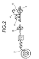
- Welding wires for tests were manufactured in the following manner. As shown in Fig. 2, a plate material 2' made of Ni-based alloy and having a width of 8mm was first rounded by rounding rolls 10 into a U sectional shape (having an opening in its upper side), and then flux was filled into the U-shaped material from a flux filling device 11 and also a conductive core wire 12 was inserted thereinto. Then the U-shaped material was further subjected to additional rounding with use of closing rolls 13. As a result, such a lap portion 2a as shown in Fig. 1 was formed so that the metal outer layer 2 should become a cylindrical shaped material. Next the cylindrical shaped material was expanded into a welding wire having a diameter of 1. 2mm for each test.
- each outer layer thickness (OLT) in Table 1 is the thickness of the plate material 2' prior to the rounding step
- the core wire diameter (CWD) is the diameter of each conductive core wire prior to the rounding step. These dimensions are decreased according to the rounding step.
- Each flux amount (FA) shown in Table 1 is the weight% of the weight of the flux to the weight of the welding wire per unit length
- each core wire amount (CWA) is the weight% of the weight of the conductive core wire to the weight of the welding wire per unit length.
- the present test was basically based on the JIS-Z-3153 (1993) T-shaped weld cracking test. More specifically, as shown in Fig. 3,two plates (base materials to be welded) P1 and P2 made of SM490A are welded into a T shape with a gap G of 1mm provided therebetween and with test bead B1 and restriction bead B2 formed thereon, and a cracking length of the test bead B1 and crater portion is found by a dye penetrative test to calculate a cracking percentage ((crack length divided by crater length) multiplied by 100).
- a bead was formed on the surface of a plate of 12 x 100 x 250mm made of SM490A to extend in a longitudinal direction thereof.
- Arc state strong or weak arc, continuity, etc. of the arc
- Spatter state was evaluated on the basis of the size and number of generated spatters in a five step levels of A, B, C, D and E in the better order of the quality.
- the evaluation criterion was based on the number of deposited spatters per 150mm of welded bead center so that A is 0-1, B is 2-5, C is 6-10, D is 11-25 and E is 26 or more. Its test results are given in Table 1. It will be seen from Table 1 that the arc state is bad and spatters tend to be easily generated in the welding wires of the comparative examples 1, 6 and 7 having no conductive core wire provided therein. This is because, in the welding wire having no conductive core wire, the arc takes place between the metal outer layer and a base material to be welded and thus the metal outer layer is first melted and the central portion of the flux cannot be sufficiently melted. As a result, the arc becomes unstable and spatters tend to easily occur.
- the arc state is bad and spatters tend to easily occur. This is because the core wire amount is small and thus the arc generation is insufficient at the conductive core wire. It will further be noted that, even in the welding wire of the comparative example 4 having a core wire amount exceeding 15 weight%, the arc state is bad and spatters tend to easily occur. This is because the flux amount is limited so that the necessary amount of non-metal flux such as an arc stabilizer is decreased.
- the arc state is bad and spatters tend to be easily generated. This is because the flux metal powder content is small, and thus the sufficient electrical conduction between the metal outer layer and conductive core wire cannot be realized and the arc generation in the conductive core wire becomes insufficient. It will also be observed that, even in the welding wire of the comparative example 9 having a flux metal powder content exceeding 80 weight%, the arc state is bad and spatters tend to be easily generated. This is because the necessary amount of the non-metal flux such as an arc stabilizer is decreased.
- the present invention has been applied to the flux-contained welding wire of the lap type having a lap portion 2a formed therein.
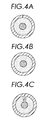
- the present invention can be applied to a welding wire of an abut O type wherein ends of the metal outer layer are not overlapped but abut as joined to each other as shown in Fig. 4A, a welding wire of a seamless type as shown in Fig. 4B, and a welding wire of a T type as shown in Fig. 4C.
- powder of any other particle shapes including flake or line can be employed.
- sectional shape of the conductive core wire has been a circle in the present embodiment, any other sectional shape such as a polygon may be used.
- the electrical conduction between the metal outer layer and conductive core wire can be realized. Therefore, even when the conductive core wire is disposed inside of the metal outer layer together with the flux without being supported by the metal outer layer, the electrical conduction of the conductive core wire with the metal outer layer via the flux enables generation of the arc between the conductive core wire and a base material to be welded. For this reason, the welding wire can be easily manufactured without the need for performing complicated manufacturing steps at the metal outer layer for the purpose of supporting the conductive core wire as in the prior art. In particular, when the average outer diameter of the metal outer layer is made as small as 2.0mm or less, the welding wire manufacturing can be facilitated.
Landscapes
- Engineering & Computer Science (AREA)
- Mechanical Engineering (AREA)
- Nonmetallic Welding Materials (AREA)
Claims (7)
- Fil de soudage contenu dans un flux, comprenant :une couche extérieure métallique (2) en forme de conduit, réalisée en Ni ou alliage à base de Ni,un flux (3) rempli à l'intérieur de ladite couche extérieure métallique (2) ; etun fil central conducteur (4) réalisé en Ni ou en alliage à base de Ni et disposé à l'intérieur de la couche extérieure métallique (2) avec ledit flux (3),caractérisé en ce que :ledit fil central conducteur (4) est disposé sans être supporté par ladite couche extérieure métallique (2) ;ledit flux (3) contient 20-80% en poids de poudre métallique granulaire par poids dudit flux ;un % en poids du poids dudit flux (3) par rapport à un poids dudit fil de soudage par longueur unitaire est établi dans une gamme de 6,5-30% en poids, etun % en poids d'un poids dudit fil central conducteur (4) par rapport à un poids dudit fil de soudage par longueur unitaire est établi dans une gamme de 1,5-15% en poids.
- Fil de soudage contenu dans un flux selon la revendication 1, dans lequel un composant principal de ladite poudre métallique compris dans ledit flux (3) est une poudre de Ni ou en alliage à base de Ni.
- Fil de soudage contenu dans un flux selon la revendication 2, dans lequel ladite poudre de Ni ou en alliage à base de Ni a un diamètre moyen de particule de 10-100 µm.
- Fil de soudage contenu dans un flux selon l'une quelconque des revendications précédentes, dans lequel ladite couche extérieure métallique (2) a un diamètre extérieur moyen de 2,0 mm ou moins.
- Fil de soudage contenu dans un flux selon la revendication 1, dans lequel ladite couche extérieure métallique a un diamètre extérieur moyen ne dépassant pas 2,0 mm ;
ledit flux (3) contient 50-60% en poids de poudre métallique en Ni ou en alliage à base de Ni par poids dudit flux, ayant un diamètre moyen de particule de 10-100 µm ;
un % en poids d'un poids dudit flux (3) par rapport au poids dudit fil de soudage par longueur unitaire est établi dans une gamme de 15, 5 - 19,5% en poids et
un % en poids d'un poids dudit fil central conducteur (4) par rapport au poids dudit fil de soudage par longueur unitaire est établi dans une gamme de 3,5-7,5% en poids. - Fil de soudage contenu dans un flux selon l'une quelconque des revendications précédentes, dans lequel ledit fil central conducteur (4) a une forme en coupe proche d'un cercle.
- Fil de soudage contenu dans un flux selon l'une quelconque des revendications précédentes, dans lequel ladite couche extérieure de métal (2) a une partie de recouvrement.
Applications Claiming Priority (2)
| Application Number | Priority Date | Filing Date | Title |
|---|---|---|---|
| JP2001220200 | 2001-07-19 | ||
| JP2001220200 | 2001-07-19 |
Publications (2)
| Publication Number | Publication Date |
|---|---|
| EP1277538A1 EP1277538A1 (fr) | 2003-01-22 |
| EP1277538B1 true EP1277538B1 (fr) | 2008-01-16 |
Family
ID=19054058
Family Applications (1)
| Application Number | Title | Priority Date | Filing Date |
|---|---|---|---|
| EP02255053A Expired - Lifetime EP1277538B1 (fr) | 2001-07-19 | 2002-07-18 | Fil à âme de flux pour le soudage |
Country Status (3)
| Country | Link |
|---|---|
| US (1) | US6710301B2 (fr) |
| EP (1) | EP1277538B1 (fr) |
| DE (1) | DE60224616T2 (fr) |
Families Citing this family (12)
| Publication number | Priority date | Publication date | Assignee | Title |
|---|---|---|---|---|
| US20060266794A1 (en) * | 2005-05-25 | 2006-11-30 | Lincoln Global, Inc. | Method and apparatus for packaging wire in a wire container |
| WO2008049080A1 (fr) * | 2006-10-18 | 2008-04-24 | Inframat Corporation | Fils à noyau nanostructuré/à base de particules superfines pour des applications de pulvérisation thermique et leurs procédés de fabrication |
| JP4943827B2 (ja) * | 2006-11-30 | 2012-05-30 | 矢崎総業株式会社 | 抵抗溶接方法及び導体ユニット |
| CN102267017A (zh) * | 2011-07-16 | 2011-12-07 | 无锡帝宝应用材料高科技有限公司 | 药芯焊丝中再包焊丝的复合焊丝 |
| CN102284804A (zh) * | 2011-08-04 | 2011-12-21 | 无锡帝宝应用材料高科技有限公司 | 高结合力纳米非晶喷涂焊丝 |
| EP2666580B1 (fr) * | 2012-05-23 | 2020-07-29 | Lincoln Electric Italia S.r.l. | Fil de soudage à âme centrale solide et son procédé de fabrication |
| CN102873464A (zh) * | 2012-10-22 | 2013-01-16 | 江苏科技大学 | 一种具有中间绝缘层的焊丝 |
| CN103978318A (zh) * | 2014-04-25 | 2014-08-13 | 浙江新锐焊接材料有限公司 | 一种圆形三明治自钎钎料及其制备方法 |
| CN111050987A (zh) * | 2017-08-02 | 2020-04-21 | 日本焊接材料株式会社 | 用于焊接不同种类材料的焊丝及其制造方法 |
| WO2019191609A1 (fr) * | 2018-03-30 | 2019-10-03 | Hobart Brothers Company | Fils tubulaires fabriqués à partir d'une bande revêtue de cuivre |
| CN110682027B (zh) * | 2019-09-17 | 2021-04-02 | 中国船舶重工集团公司第七二五研究所 | 具有无缝焊芯的高锰奥氏体低温钢用电焊条及制备方法 |
| CN113953712B (zh) * | 2021-10-11 | 2022-11-04 | 西安理工大学 | Ta1-q235复合板对接焊接用材料及焊接方法 |
Family Cites Families (12)
| Publication number | Priority date | Publication date | Assignee | Title |
|---|---|---|---|---|
| BE675192A (fr) | ||||
| GB1383304A (en) | 1971-02-09 | 1974-02-12 | British Oxygen Co Ltd | Welding consumables |
| GB1369843A (en) | 1971-09-10 | 1974-10-09 | Pyrotenax Ltd | Manufacture of composite welding electrodes |
| FR2158621A5 (en) | 1971-10-26 | 1973-06-15 | Soudure Autogene Francaise | Hollow welding electrode - contg a filler material and undulating metal rod or wire |
| FR2177134A5 (en) | 1972-03-20 | 1973-11-02 | British Insulated Callenders | Composite electrode wires - for arc spraying |
| US4149063A (en) * | 1977-03-28 | 1979-04-10 | The International Nickel Company, Inc. | Flux cored wire for welding Ni-Cr-Fe alloys |
| ZA801080B (en) | 1979-03-13 | 1981-03-25 | Bekaert Sa Nv | Welding electrode |
| US4449031A (en) * | 1980-04-16 | 1984-05-15 | Teledyne Industries, Inc. | Tubular composite arc welding electrode for vertical up welding of stainless steel and nickel-base alloys |
| US4423119A (en) * | 1981-11-05 | 1983-12-27 | Brown Roger K | Composite wire for forming wear resistant coatings, and method of manufacture |
| US5225661A (en) * | 1989-09-11 | 1993-07-06 | The Lincoln Electric Company | Basic metal cored electrode |
| DE19523400A1 (de) | 1995-06-28 | 1997-01-02 | Castolin Sa | Verfahren zum Herstellen eines Kerndrahtes für Schweißelektroden sowie Elektroden-Kerndraht |
| US6153847A (en) | 1997-06-06 | 2000-11-28 | Mitsui Engineering & Shipbuilding Company | Welding member and welding method |
-
2002
- 2002-07-17 US US10/196,815 patent/US6710301B2/en not_active Expired - Lifetime
- 2002-07-18 DE DE60224616T patent/DE60224616T2/de not_active Expired - Lifetime
- 2002-07-18 EP EP02255053A patent/EP1277538B1/fr not_active Expired - Lifetime
Also Published As
| Publication number | Publication date |
|---|---|
| DE60224616D1 (de) | 2008-03-06 |
| US20030052113A1 (en) | 2003-03-20 |
| US6710301B2 (en) | 2004-03-23 |
| DE60224616T2 (de) | 2009-01-15 |
| EP1277538A1 (fr) | 2003-01-22 |
Similar Documents
| Publication | Publication Date | Title |
|---|---|---|
| EP1277538A1 (fr) | Fil à âme de flux pour le soudage | |
| EP2012398B1 (fr) | Bougie d'allumage | |
| EP2610361B1 (fr) | Fil de soudage à flux incorporé en acier au carbone et procédé de soudage à l'arc | |
| JP2003211285A (ja) | 溶接ワイヤおよびその製造方法 | |
| US6765167B2 (en) | Electric contact member and production method thereof | |
| US4205119A (en) | Wrapped tantalum diffusion barrier | |
| CN101867098A (zh) | 铝导体端子装置及其制造方法 | |
| US8604390B2 (en) | Weld wire electrode for gas metal arc welding | |
| CN1902792A (zh) | 碳刷及其制造的方法和材料 | |
| JP6148925B2 (ja) | 導電用Al合金板材 | |
| JP4263879B2 (ja) | 溶接用フラックス入りワイヤ | |
| US5512240A (en) | Tungsten electrode material | |
| US4469395A (en) | Electrical termination comprising a soft aluminum lead and a terminal of hard aluminum alloy butt-welded thereto | |
| EP2555355B1 (fr) | Bougie d'allumage | |
| JP3272526B2 (ja) | Al基材料表面への肉盛溶接用複合ワイヤおよび耐摩耗性Al基部材 | |
| EP4131658A1 (fr) | Nouvelle pièce d'aluminium d'extrémité | |
| JPH06650A (ja) | コンタクトチップ及びその製造方法 | |
| US2697771A (en) | Weld rod and method of making | |
| EP3616827B1 (fr) | Structure de jonction, son procédé de fabrication, moteur électrique et son procédé de fabrication | |
| JP3217536B2 (ja) | Al基材料への肉盛溶接用複合ワイヤ | |
| CN121589404A (zh) | 一种控制镍基合金复合板焊接变形的焊接方法 | |
| JP2006159245A (ja) | 抵抗溶接用電極 | |
| JPH04339571A (ja) | 抵抗スポット溶接性に優れたアルミニウム合金複合板 | |
| JP2007237209A (ja) | 抵抗溶接方法 | |
| JP2580158B2 (ja) | アルミニウム合金溶加材 |
Legal Events
| Date | Code | Title | Description |
|---|---|---|---|
| PUAI | Public reference made under article 153(3) epc to a published international application that has entered the european phase |
Free format text: ORIGINAL CODE: 0009012 |
|
| AK | Designated contracting states |
Kind code of ref document: A1 Designated state(s): AT BE BG CH CY CZ DE DK EE ES FI FR GB GR IE IT LI LU MC NL PT SE SK TR |
|
| AX | Request for extension of the european patent |
Free format text: AL;LT;LV;MK;RO;SI |
|
| 17P | Request for examination filed |
Effective date: 20030612 |
|
| AKX | Designation fees paid |
Designated state(s): DE GB IT NL SE |
|
| 17Q | First examination report despatched |
Effective date: 20061129 |
|
| GRAP | Despatch of communication of intention to grant a patent |
Free format text: ORIGINAL CODE: EPIDOSNIGR1 |
|
| GRAS | Grant fee paid |
Free format text: ORIGINAL CODE: EPIDOSNIGR3 |
|
| GRAA | (expected) grant |
Free format text: ORIGINAL CODE: 0009210 |
|
| GRAL | Information related to payment of fee for publishing/printing deleted |
Free format text: ORIGINAL CODE: EPIDOSDIGR3 |
|
| GRAS | Grant fee paid |
Free format text: ORIGINAL CODE: EPIDOSNIGR3 |
|
| AK | Designated contracting states |
Kind code of ref document: B1 Designated state(s): DE GB IT NL SE |
|
| REG | Reference to a national code |
Ref country code: GB Ref legal event code: FG4D |
|
| RIN1 | Information on inventor provided before grant (corrected) |
Inventor name: YOSHIZAWA, TOSHIO Inventor name: FUJITA, TOSHIAKI Inventor name: TANAKA, KANEHISA Inventor name: ITO, TADASHI Inventor name: SAITO, TEIICHIRO Inventor name: TSUJIKAWA, KAZUO |
|
| REF | Corresponds to: |
Ref document number: 60224616 Country of ref document: DE Date of ref document: 20080306 Kind code of ref document: P |
|
| REG | Reference to a national code |
Ref country code: SE Ref legal event code: TRGR |
|
| PLBE | No opposition filed within time limit |
Free format text: ORIGINAL CODE: 0009261 |
|
| STAA | Information on the status of an ep patent application or granted ep patent |
Free format text: STATUS: NO OPPOSITION FILED WITHIN TIME LIMIT |
|
| 26N | No opposition filed |
Effective date: 20081017 |
|
| PGFP | Annual fee paid to national office [announced via postgrant information from national office to epo] |
Ref country code: IT Payment date: 20210524 Year of fee payment: 20 Ref country code: NL Payment date: 20210622 Year of fee payment: 20 |
|
| PGFP | Annual fee paid to national office [announced via postgrant information from national office to epo] |
Ref country code: SE Payment date: 20210519 Year of fee payment: 20 Ref country code: GB Payment date: 20210519 Year of fee payment: 20 |
|
| PGFP | Annual fee paid to national office [announced via postgrant information from national office to epo] |
Ref country code: DE Payment date: 20210730 Year of fee payment: 20 |
|
| REG | Reference to a national code |
Ref country code: DE Ref legal event code: R071 Ref document number: 60224616 Country of ref document: DE |
|
| REG | Reference to a national code |
Ref country code: NL Ref legal event code: MK Effective date: 20220717 |
|
| REG | Reference to a national code |
Ref country code: GB Ref legal event code: PE20 Expiry date: 20220717 |
|
| REG | Reference to a national code |
Ref country code: SE Ref legal event code: EUG |
|
| PG25 | Lapsed in a contracting state [announced via postgrant information from national office to epo] |
Ref country code: GB Free format text: LAPSE BECAUSE OF EXPIRATION OF PROTECTION Effective date: 20220717 |