EP1277559A1 - Procédé et dispositif de fermeture de moule pour des presses à injecter - Google Patents
Procédé et dispositif de fermeture de moule pour des presses à injecter Download PDFInfo
- Publication number
- EP1277559A1 EP1277559A1 EP02014779A EP02014779A EP1277559A1 EP 1277559 A1 EP1277559 A1 EP 1277559A1 EP 02014779 A EP02014779 A EP 02014779A EP 02014779 A EP02014779 A EP 02014779A EP 1277559 A1 EP1277559 A1 EP 1277559A1
- Authority
- EP
- European Patent Office
- Prior art keywords
- press
- tie
- platen
- locking
- bushes
- Prior art date
- Legal status (The legal status is an assumption and is not a legal conclusion. Google has not performed a legal analysis and makes no representation as to the accuracy of the status listed.)
- Granted
Links
- 238000001746 injection moulding Methods 0.000 title claims abstract description 16
- 238000000034 method Methods 0.000 title claims abstract description 13
- 230000000875 corresponding effect Effects 0.000 claims abstract description 17
- 238000006073 displacement reaction Methods 0.000 claims abstract description 17
- 230000002596 correlated effect Effects 0.000 claims abstract description 6
- 230000001276 controlling effect Effects 0.000 claims description 9
- 239000000463 material Substances 0.000 claims description 6
- 230000002093 peripheral effect Effects 0.000 claims description 5
- 230000001360 synchronised effect Effects 0.000 claims description 5
- 230000006698 induction Effects 0.000 claims 1
- 239000000243 solution Substances 0.000 description 17
- 238000013459 approach Methods 0.000 description 2
- 238000002347 injection Methods 0.000 description 2
- 239000007924 injection Substances 0.000 description 2
- 238000000465 moulding Methods 0.000 description 2
- 230000000284 resting effect Effects 0.000 description 2
- 238000006243 chemical reaction Methods 0.000 description 1
- 230000003750 conditioning effect Effects 0.000 description 1
- 238000007596 consolidation process Methods 0.000 description 1
- 230000008878 coupling Effects 0.000 description 1
- 238000010168 coupling process Methods 0.000 description 1
- 238000005859 coupling reaction Methods 0.000 description 1
- 238000010586 diagram Methods 0.000 description 1
- 230000009977 dual effect Effects 0.000 description 1
- 239000012530 fluid Substances 0.000 description 1
- 238000012986 modification Methods 0.000 description 1
- 230000004048 modification Effects 0.000 description 1
- 238000011017 operating method Methods 0.000 description 1
- 238000006467 substitution reaction Methods 0.000 description 1
- 230000002463 transducing effect Effects 0.000 description 1
- 238000012546 transfer Methods 0.000 description 1
Images



Classifications
-
- B—PERFORMING OPERATIONS; TRANSPORTING
- B29—WORKING OF PLASTICS; WORKING OF SUBSTANCES IN A PLASTIC STATE IN GENERAL
- B29C—SHAPING OR JOINING OF PLASTICS; SHAPING OF MATERIAL IN A PLASTIC STATE, NOT OTHERWISE PROVIDED FOR; AFTER-TREATMENT OF THE SHAPED PRODUCTS, e.g. REPAIRING
- B29C45/00—Injection moulding, i.e. forcing the required volume of moulding material through a nozzle into a closed mould; Apparatus therefor
- B29C45/17—Component parts, details or accessories; Auxiliary operations
- B29C45/64—Mould opening, closing or clamping devices
- B29C45/68—Mould opening, closing or clamping devices hydro-mechanical
-
- B—PERFORMING OPERATIONS; TRANSPORTING
- B29—WORKING OF PLASTICS; WORKING OF SUBSTANCES IN A PLASTIC STATE IN GENERAL
- B29C—SHAPING OR JOINING OF PLASTICS; SHAPING OF MATERIAL IN A PLASTIC STATE, NOT OTHERWISE PROVIDED FOR; AFTER-TREATMENT OF THE SHAPED PRODUCTS, e.g. REPAIRING
- B29C45/00—Injection moulding, i.e. forcing the required volume of moulding material through a nozzle into a closed mould; Apparatus therefor
- B29C45/17—Component parts, details or accessories; Auxiliary operations
- B29C45/64—Mould opening, closing or clamping devices
- B29C45/68—Mould opening, closing or clamping devices hydro-mechanical
- B29C2045/686—Mould opening, closing or clamping devices hydro-mechanical using a screw and nut mechanism for mould closing and a mould clamping ram acting on another nut
Definitions
- the present invention refers to injection moulding machines for plastic materials, and in particular relates to a method and to a mould clamping press according to which use is made of a clamping device for clamping a mould, by which it is possible to operate with precision and at high speed.
- clamping presses for the closure of a mould, that is to say clamping presses having two platens, and presses having three platens provided with two or more peripheral tie-rods which extend longitudinally to the press.
- clamping presses having three platens
- these comprise a first stationary platen for supporting a half mould, a second movable platen for supporting the other one of the half moulds, sliding along guide rods, and a third stationary platen forming part of a reaction structure, to which a toggle system is connected to control the sliding of the movable platen between an open condition and a closed condition of the mould, and the clamping of the same mould.
- Presses of this kind require an expensive and bulky structure, and highly complex control systems necessary to generate the high clamping forces for tightly closing the mould, with mould closing and opening times compatible with the length of the entire operative cycle of the machine.
- An alternative configuration to reduce costs and overall dimensions contemplates the use of only two platens, including a stationary platen to support a first half mould, and a movable platen to support a second half mould, which is made to slide along horizontal guides by means of hydraulical actuators or other types of control systems.
- a two platen press also comprises tie-rods which extend from one platen to the other one, and engage with mechanical clamping devices operated at the end of the working stroke during which the movable platen approaches the stationary platen, before exerting the high clamping force for closing the mould, or at the time of reopening of the mould at the end of each injection cycle.
- the tie-rods are rigidly fastened and protrude jutting out from one of the platens, in such a way that their extremities engage with clamping jaws or other clamping devices disposed on the other platen of the press; the clamping jaws must be operated beforehand to engage the tie-rods which subsequently are drawn by means of hydraulic actuators capable of exerting the necessary clamping force or tonnage for closing the mould.
- pauses are required for operating the clamping devices; such pauses have significant repercussions on the output of this type of machine.
- US-A-5,066,217; US-A-5,417,913 and US-A-6,186,770 show other types of two platen clamping presses.
- US-A-5,066,217 and US-A-5,417,913 show a two platen presses whose tie-rods are axially movable with respect to the platens supporting the half moulds, and in which use is also made of mechanical systems for locking the platens to the tie-rods, which substantially comprise radially movable half nuts, or angularly rotatable coupling members which engage with corresponding screw threads or annular ribs on the tie-rods of the press.
- Presses of this kind again present the same drawbacks inherent in the clamping and closing devices of the patents previously referred to; in particular, they present a greater complexity of the system for locking the platens to the tie-rods and inter-cycle times which are still considered high for this kind of press.
- US-A-6,186,770 which represents the closest prior art in respect to the present invention, also shows a two platen press in which the tie-rods are axially secured to one of the platens, and in which the other platen of the press is provided with a mechanical connection with each tie-rod, substantially comprising an internally threaded bush member which engages by screwing onto a screw threaded portion of the corresponding tie-rod, both in order to cause the sliding of the movable platen, and in order to generate the tonnage necessary for the tight clamping of the mould.
- a belt system is provided to synchronise the rotation of all the bush members.
- the press comprises a first control means to cause the rotation of the bushes whenever the movable platen must be moved forward or backward, and second independent control means to rotate the bushes themselves, or alternatively the same tie-rods, whenever the tonnage for clamping the mould must be exerted.
- the threaded bushes in addition to generation of the tonnage for clamping the mould, also serve to cause the sliding displacement of the movable platen, thereby resulting in frictional forces and stress between the screw threads.
- the main object of the present invention is to provide a method and a two platen press for injection moulding, which make use of a locking device for the closure and locking of the platens to the tie-bars of a press, which is capable of obviating the aforementioned drawbacks.
- one object of the present invention is to provide a method for clamping a two platen press, as referred to above, allowing extremely short clamping times, suitable for fast cycle machines, and which does not require any particular or complex safety system, thereby ensuring the utmost speed and precision during the closing and tight clamping steps of a mould.
- a further object of the present invention is to provide an injection moulding press of two platens type, provided with a clamping system for clamping the mould and securing the platens to the tie-rods which, in addition to possessing extremely short resting times, is also extremely functionally simplified in that the locking of the platens to the tie-rods and the tight clamping of the mould, take place simultaneously and in synchronism on all the rods of the press, without causing frictional forces.
- a still further object of the present invention is to provide a clamping device of the type referred to above, by which it is possible to use separate control systems for the displacement of the movable platen and for locking at the same time the platens to the tie-rods, ensuring in all cases a fast and immediate clamping action whatever the final position of the movable platen with respect to the stationary one.
- a method for clamping a mould of an injection moulding press of the type comprising:
- a locking device for locking a tie-rod to a mould supporting platen of a moulding press said locking device comprising:
- a press for injection moulding of plastic materials, comprising:
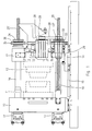
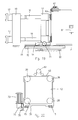
- a two platen press for injection moulding of plastic materials substantially comprises a first stationary platen 10 for supporting a first half mould 11, and a second movable platen 12 for supporting a second half mould 13, aligned according to the longitudinal axis of the press.
- the movable platen 12 is mounted on a saddle 14 sliding along guide rails 15 parallelly arranged to the longitudinal axis of the press.
- each tie-rod 16 is slidably supported by the stationary platen 10, and is connected to any kind of actuator capable of causing the same tie-rod to shift slightly in an axial direction for a short stroke.
- the actuator can be a piston cylinder unit 17, capable of generating a high force or tonnage necessary for the tightly clamping the two half moulds 11 and 13.
- each tie-rod as shown in Fig. 3, presents a threaded portion 16D which extends axially through a locking bush 18; the bush 18 is supported by the movable platen 12 to freely rotate with the possibility of shifting slightly in an axial direction for the reasons explained further on, with reference to the Figs. from 5 to 8 of the accompanying drawings.
- the bush 18 is supported by the movable platen 12 by bearings 19 designed to enable the same bush to freely and frictionless rotate and to shift for a short axial clearance as specified further on.
- Guide means are also provided to maintain the bush 18 in a central position with the screw thread 23 constantly disengaged from the screw thread 24 of the corresponding rod 16, and to allow a relative axial movement, for the purposes specified previously; said guide means can be achieved in any way whatsoever; for example, as shown in Figs. from 5 to 8, the bush 18 can be provided on the outer surface with an annular slot 21 in which penetrate a guide roller 22A idly supported at the end of an elastically flexible guide pin 22; the pin 22 with the guide roller 22A protrudes radially from the movable platen 12 to guide and maintain the bush 18, during rotation, appropriately centred with respect to the threaded portion 16D of the rod 16.
- the bush 18 is able to rotate freely without frictional forces and without contact with the internal screw thread 23 of the bush and the corresponding external screw thread 24 of the rod 16, as shown in Fig. 5 of the accompanying drawings.
- the two screw threads present trapezoidal threads with similarly slanted sides, to transfer to the bush 18 and from the latter to the movable platen 12, all the forces exerted on the tie-rods 16, without subjecting the same screw threads on excessive stress.
- the press is provided with control means for controlling the movable platen, operated independently of the control means for the tie-rods; said control means consists of hydraulic cylinders 17 which act to shift the movable platen 12 towards and away from the stationary platen 10, respectively upon the closing and opening of the mould, and suitable means for controlling the synchronised rotation of all the locking bushes 18, in a way correlated to the sliding displacement of the movable platen 12.
- the means for controlling the movement of the movable platen 12 comprise, on each side of the press, a ball bearing screw 25, 25' connected to the stationary platen 10, which engages with a screw nut 26, 26' rotatingly supported on one side of the movable platen 12.
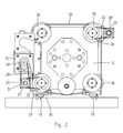
- One of the two screw nuts for example the screw nut 26 is in turn provided with a pulley 27 connected, by means of a belt 28, to the pulley 29 of an electric control motor 30.
- the screw nut 26 is in turn connected, by means of a second pulley 32 and a belt 33, to a pulley 34 coaxially arranged to the locking bush 18 of one of the tie-rods 16 in the lower left-hand corner of Fig. 2.
- the bushes 18 for locking the movable platen 12 to the tie-rods 16, are in turn controlled to rotate in synchronism, for example by means of a positive drive belt 35 which winds around corresponding pulleys 36 coaxially arranged to the bushes 18, as shown in Fig. 2 and in the enlarged detail of Fig. 3.
- the screw threads 23 of the bushes 18 are not in contact with the screw threads 24 of the tie-rods; consequently, the bushes 18 can be made to rotate freely without any contact and without frictional forces between the screw threads 23, 24 due to the presence of the guide pin 22 for centring and guiding the bushes.
- the guide pin 22 is slightly elastically bent by the thrust exerted by a side of the slot 21 on the roller 22A.
- the movable platen 12 can now be made to move backward again, by reversing the motor 30 of the screw nut/ball screw system 25 and 26, making the bushes 18 once again rotate in synchronism to maintain their screw threads disengaged from those of the rods 16 throughout the entire opening stroke of the press.
- the pin 22 performs the dual function of a guiding and centring the threaded bush 18, and of a biasing means to return and maintain the bush in a disengaged condition of the screw threads; these guiding and centring functions of the threaded bush 18 may be obtained by different means either of the passive type, or of the active type in substitution of the flexible pins 22.
- the pins 22 may be replaced by two packs of Belleville washers acting on the two ends of each threaded bush 18, or by positively controlling the movement of the bush in one or both directions, by means of an appropriate hydraulic, pneumatic, electromagnetic or other type of actuator or control system.
- the most highly innovative feature of the press and its operative method primarily consists in the use of tie-rods which are movable with respect to both the mould platens, and in the use of locking bushes rotatingly and axially movably supported by one of the platens of the press, and in which the bushes present an internal screw thread which is maintained constantly disengaged and not in contact with a corresponding screw thread at one extremity of the tie-rods, while the same bushes are made to rotate in synchronism during the sliding displacement of the movable platen of the press, and in a way correlated to the forward and backward movement of the same platen.
- a first control means for controlling the movable platen consisting of a screw/nut system 25, 26 operated by an electric motor 30, and a second control means consisting of the hydraulic cylinders 17 to axially move the rods 16 and secure them to the platens 10 and 12 to exert the necessary force ensuring the clamping and tight closing of the two half moulds 11 and 13.
- the system for synchronising the rotation of the locking bushes 18 and the sliding movement of the movable platen 12 makes use of the screw nut system 25, 26 directly as a means of transducing the sliding movement of the movable platen and of correlation with the rotation of the bushes 18.
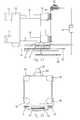
- FIGs. 9 and 10 A second solution is shown in Figs. 9 and 10 in which the screw/nut system 25, 26 of the previous example has been replaced by at least one hydraulic cylinder 40, two in the case shown, fastened to the stationary platen 10, while its rod 41 is connected to the movable platen 12.
- the synchronisation between the rotation of the various bushes 18 for locking the platen 12 to the rods 16, and the sliding movement of the movable platen are always obtained by means of a mechanical movement transducer comprising a fixed ball-type screw 42 and a nut screw 43 rotatingly supported on one side of the movable platen 12, centrally disposed beneath the press; a pulley 44 rotates with the nut screw 42 to control the driving belt 35 which winds around the pulley 36 to synchronise the rotation of the various bushes 18 locking the platen 12 to the rods 16 of the press.
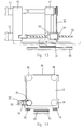
- Figs. 11 and 12 show a third embodiment, substantially similar to that of Figs. 9 and 10, the only difference being that now the hydraulic cylinder 40 which controls the sliding of the movable platen 12, has been replaced by a rack type control device comprising a rack 45 on one side of the press, fastened to the stationary platen 10, and a gear wheel 46 connected to an electric motor 47 supported by the movable platen 12. Consequently, in Figs. 11 and 12 the same reference numbers as in Figs. 9 and 10 have been used to indicate similar or equivalent parts.
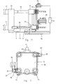
- Figs. 13 and 14 show a fourth possible solution which differs from the preceding ones in that the means for controlling the sliding of the movable platen 12, in this case consists of a linear electric motor, centrally disposed beneath the platens of the press, comprising a stationary member 50 and a movable member 51 connected to the movable platen 12, as schematically shown.
- the means for controlling the sliding of the movable platen 12 in this case consists of a linear electric motor, centrally disposed beneath the platens of the press, comprising a stationary member 50 and a movable member 51 connected to the movable platen 12, as schematically shown.
- Control of the synchronised rotation of the various locking bushes 18 on the rods 16, is also achieved by means of a belt drive 35, 36, and is derived from the linear movement of the movable platen 12 by means of a screw/nut system 52, 53, in which the rotation of the screw nut 53 is transmitted to the locking bush of at least one of the drawing rods, by means of a belt drive 54, as shown, or in any other suitable way.
- Figs. 15 and 16 show a fifth solution which differs from the preceding solutions in that use is made of an electronic interlocking system for synchronising the rotation of the locking bushes 18, with one another and in a way correlated to the sliding movement of the movable platen 12.
- the control of the movable platen 12 is again achieved by means of a screw/nut system 25, 26 and 25', 26' operated by a motor 30 in a way similar to the solution of Fig. 1; in this case, the control to the second nut screw 26' is transmitted by means of a first mechanical belt drive 58, 59, while the synchronisation between the movement of the platen 12 and the rotation of the bushes 18, is achieved by means of an electric or electronic transducer comprising, for example, a linear movement or positional transducer 60 operatively connected to the movable platen 12 of the press; the output signal of the transducer 60 is transmitted to a port of an electronic control unit 61 which governs the running of an electric motor 62 which, by means of a second belt drive 63, or in any other way, drives the synchronised rotation of the various locking bushes 18 on the rods 16 of the press.
- an electric or electronic transducer comprising, for example, a linear movement or positional transducer 60 operatively connected to the
- Figs. 17 and 18 show a sixth solution which, like the previous solution, uses an electronic system for the synchronisation and coordination between the movement of the movable platen 12 and the rotation of the clamping bushes on the rods 16.
- Figs. 19 and 20 show a seventh solution which also makes use of an electronic synchronising system and which, on the contrary, uses a rack-type control 70, 71 and an electric motor 72 for the displacement of the movable platen 12.
- FIGs. 21 and 22 show an eighth solution which also uses an electric or electronic synchronising system, similar to that of the previous solutions, in which the movable platen 12 is now driven by a linear control motor 50, 51 similar to that of the solution of Fig. 14.
Landscapes
- Engineering & Computer Science (AREA)
- Manufacturing & Machinery (AREA)
- Mechanical Engineering (AREA)
- Moulds For Moulding Plastics Or The Like (AREA)
- Injection Moulding Of Plastics Or The Like (AREA)
- Casting Or Compression Moulding Of Plastics Or The Like (AREA)
Applications Claiming Priority (2)
| Application Number | Priority Date | Filing Date | Title |
|---|---|---|---|
| IT2001MI001538A ITMI20011538A1 (it) | 2001-07-19 | 2001-07-19 | Metodo e pressa per la chiusura di stampi in macchine di stampaggio ad iniezione |
| ITMI20011538 | 2001-07-19 |
Publications (2)
| Publication Number | Publication Date |
|---|---|
| EP1277559A1 true EP1277559A1 (fr) | 2003-01-22 |
| EP1277559B1 EP1277559B1 (fr) | 2006-09-20 |
Family
ID=11448087
Family Applications (1)
| Application Number | Title | Priority Date | Filing Date |
|---|---|---|---|
| EP02014779A Expired - Lifetime EP1277559B1 (fr) | 2001-07-19 | 2002-07-04 | Procédé et dispositif de fermeture de moule pour des presses à injecter |
Country Status (7)
| Country | Link |
|---|---|
| US (1) | US6821463B2 (fr) |
| EP (1) | EP1277559B1 (fr) |
| AT (1) | ATE340063T1 (fr) |
| BR (1) | BR0202897B1 (fr) |
| DE (1) | DE60214802T2 (fr) |
| ES (1) | ES2272612T3 (fr) |
| IT (1) | ITMI20011538A1 (fr) |
Cited By (10)
| Publication number | Priority date | Publication date | Assignee | Title |
|---|---|---|---|---|
| EP1378335A1 (fr) * | 2002-07-04 | 2004-01-07 | Demag Ergotech GmbH | Mécanisme de fermeture pour une machine à mouler par injection |
| EP2228192A1 (fr) * | 2009-03-14 | 2010-09-15 | Sumitomo (SHI) Demag Plastics Machinery GmbH | Machine de moulage par injection dotée d'un dispositif de traction de chapeau |
| CN102039553A (zh) * | 2010-10-30 | 2011-05-04 | 朱文 | 一种阀门密封面研磨装置夹持机构的同步联动件 |
| CN102049727A (zh) * | 2010-11-01 | 2011-05-11 | 朱文 | 一种阀门密封面研磨装置的夹持机构 |
| CN104625721A (zh) * | 2015-02-05 | 2015-05-20 | 苏州鸿普精密模具有限公司 | 压缩机内芯压装机的电感式气缸位移推顶模组 |
| CN107263794A (zh) * | 2017-07-31 | 2017-10-20 | 嘉善梦溪服饰辅料厂(普通合伙) | 一种卧式自动化注塑装置 |
| CN108655703A (zh) * | 2018-07-18 | 2018-10-16 | 大连智云自动化装备股份有限公司 | 主轴承盖压头装置 |
| CN109605682A (zh) * | 2018-12-04 | 2019-04-12 | 江苏东弘塑业有限公司 | 注塑模具 |
| CN110154341A (zh) * | 2018-02-12 | 2019-08-23 | 宜得世股份有限公司 | 全电式两板直压锁模射出成型机 |
| CN110802820A (zh) * | 2019-12-05 | 2020-02-18 | 山东通佳智能装备有限公司 | 一种注塑机的双功能电动调模机构 |
Families Citing this family (19)
| Publication number | Priority date | Publication date | Assignee | Title |
|---|---|---|---|---|
| JP2005104071A (ja) * | 2003-10-01 | 2005-04-21 | Toyota Motor Corp | 成形装置および専用型の段替方法 |
| US7156652B2 (en) * | 2003-10-03 | 2007-01-02 | Daiwa Kasei Industry Co., Ltd. | Motor-driven injection molding apparatus |
| US7001173B1 (en) * | 2004-09-24 | 2006-02-21 | En Te Chu | Mold guiding device |
| JP4794906B2 (ja) * | 2005-05-20 | 2011-10-19 | 東芝機械株式会社 | 型締装置及び成形機 |
| USD559285S1 (en) * | 2005-10-03 | 2008-01-08 | Galomb David E | Injection molding machine |
| JP2007136961A (ja) * | 2005-11-21 | 2007-06-07 | Sumitomo Heavy Ind Ltd | 射出装置及び射出装置に備えられた複数の軸の軸力差調整方法 |
| US7449139B2 (en) * | 2006-05-23 | 2008-11-11 | Husky Injection Molding Systems Ltd. | Molding-system platen actuator |
| US7484954B2 (en) * | 2006-06-13 | 2009-02-03 | Husky Injection Molding Systems Ltd. | Molding-system locking mechanism |
| US7479005B2 (en) * | 2007-04-24 | 2009-01-20 | Husky Injection Molding Systems Ltd | Molding system having clamp actuator having actuator mount |
| JP5001724B2 (ja) * | 2007-06-12 | 2012-08-15 | 株式会社小松製作所 | スライド位置検出装置及びプレス機械 |
| CA3001196C (fr) * | 2015-10-23 | 2023-08-22 | Husky Injection Molding Systems Ltd. | Recipients et fermetures |
| AT518464B1 (de) | 2016-04-08 | 2017-11-15 | Engel Austria Gmbh | Schließeinheit für eine Formgebungsmaschine |
| DE102017117934A1 (de) | 2017-08-07 | 2019-02-07 | Arburg Gmbh + Co Kg | Formschließeinheit für eine Spritzgießmaschine |
| CN107599329A (zh) * | 2017-09-05 | 2018-01-19 | 华南理工大学 | 二板注塑机承载螺旋副同步跟随动模板的锁模机构及方法 |
| CN108555239A (zh) * | 2018-05-31 | 2018-09-21 | 广西玉柴机器股份有限公司 | 一种船用柴油机气缸体手工脱模芯盒及脱模方法 |
| DE102019126695A1 (de) * | 2019-10-02 | 2021-04-08 | Werkzeugbau Siegfried Hofmann Gmbh | Vorrichtung zum Verarbeiten eines Partikelschaummaterials zum Herstellen eines Partikelschaumformteils |
| CN111673986A (zh) * | 2020-06-06 | 2020-09-18 | 盐城卓扬汽车部件有限公司 | 一种汽车前门总成零件生产冲床模具 |
| US12539648B2 (en) * | 2022-02-17 | 2026-02-03 | Nike, Inc. | Mold system, mold opening apparatus, and methods for opening and closing a mold assembly |
| CN117183242B (zh) * | 2023-08-17 | 2024-07-05 | 苏州顺兴精密模具有限公司 | 一种带有校准机构的双浇口注塑用模具 |
Citations (3)
| Publication number | Priority date | Publication date | Assignee | Title |
|---|---|---|---|---|
| GB1128454A (en) * | 1965-11-04 | 1968-09-25 | Pressenwerk Freital Veb | Improvements in and relating to die-casting machines, presses or pressure casting machines |
| US3604058A (en) * | 1967-12-22 | 1971-09-14 | Alfred Fischbach | Injection molding apparatus |
| US5135385A (en) * | 1989-12-15 | 1992-08-04 | Ube Industries, Ltd. | Clamping system |
Family Cites Families (9)
| Publication number | Priority date | Publication date | Assignee | Title |
|---|---|---|---|---|
| US2916768A (en) | 1955-03-19 | 1959-12-15 | Ind V H V Lohuizen & Co Nv | Locking device for injection molding machines |
| DE1159137B (de) | 1959-08-06 | 1963-12-12 | Friedrich Stuebbe | Formenschliessvorrichtung an Druck- und Spritzgiessmaschinen |
| US6179607B1 (en) * | 1988-07-08 | 2001-01-30 | Fanuc Ltd | Two-platen mold-clamping apparatus |
| US5188850A (en) | 1990-07-27 | 1993-02-23 | Nissie Jushi Kogyo K.K. | Clamping apparatus for molding machine |
| US5192557A (en) | 1990-07-27 | 1993-03-09 | Nissei Jushi Kogyo K.K. | Clamping apparatus for molding machine |
| US5066217A (en) | 1990-08-08 | 1991-11-19 | Ube Industries, Ltd. | Clamping apparatus for an injection molding machine |
| US5417913A (en) | 1993-11-29 | 1995-05-23 | Arend; Donald P. | Injection molding system with removable tie rods |
| DE19719870A1 (de) | 1997-05-12 | 1998-11-19 | Hemscheidt Maschinentechnik Gm | Schließeinheit für eine Kunststoffspritzgießmaschine |
| US6186770B1 (en) | 1999-03-05 | 2001-02-13 | Amir Ziv-Av | Clamping assembly for injection molding apparatus |
-
2001
- 2001-07-19 IT IT2001MI001538A patent/ITMI20011538A1/it unknown
-
2002
- 2002-07-04 AT AT02014779T patent/ATE340063T1/de not_active IP Right Cessation
- 2002-07-04 DE DE60214802T patent/DE60214802T2/de not_active Expired - Fee Related
- 2002-07-04 EP EP02014779A patent/EP1277559B1/fr not_active Expired - Lifetime
- 2002-07-04 ES ES02014779T patent/ES2272612T3/es not_active Expired - Lifetime
- 2002-07-09 US US10/190,603 patent/US6821463B2/en not_active Expired - Fee Related
- 2002-07-12 BR BRPI0202897-2A patent/BR0202897B1/pt not_active IP Right Cessation
Patent Citations (3)
| Publication number | Priority date | Publication date | Assignee | Title |
|---|---|---|---|---|
| GB1128454A (en) * | 1965-11-04 | 1968-09-25 | Pressenwerk Freital Veb | Improvements in and relating to die-casting machines, presses or pressure casting machines |
| US3604058A (en) * | 1967-12-22 | 1971-09-14 | Alfred Fischbach | Injection molding apparatus |
| US5135385A (en) * | 1989-12-15 | 1992-08-04 | Ube Industries, Ltd. | Clamping system |
Cited By (15)
| Publication number | Priority date | Publication date | Assignee | Title |
|---|---|---|---|---|
| EP1378335A1 (fr) * | 2002-07-04 | 2004-01-07 | Demag Ergotech GmbH | Mécanisme de fermeture pour une machine à mouler par injection |
| EP2228192A1 (fr) * | 2009-03-14 | 2010-09-15 | Sumitomo (SHI) Demag Plastics Machinery GmbH | Machine de moulage par injection dotée d'un dispositif de traction de chapeau |
| CN102039553A (zh) * | 2010-10-30 | 2011-05-04 | 朱文 | 一种阀门密封面研磨装置夹持机构的同步联动件 |
| CN102039553B (zh) * | 2010-10-30 | 2012-12-26 | 朱文 | 一种阀门密封面研磨装置夹持机构的同步联动件 |
| CN102049727A (zh) * | 2010-11-01 | 2011-05-11 | 朱文 | 一种阀门密封面研磨装置的夹持机构 |
| CN102049727B (zh) * | 2010-11-01 | 2012-08-22 | 朱文 | 一种阀门密封面研磨装置的夹持机构 |
| CN104625721A (zh) * | 2015-02-05 | 2015-05-20 | 苏州鸿普精密模具有限公司 | 压缩机内芯压装机的电感式气缸位移推顶模组 |
| CN104625721B (zh) * | 2015-02-05 | 2017-01-11 | 苏州鸿普精密模具有限公司 | 压缩机内芯压装机的电感式气缸位移推顶模组 |
| CN107263794A (zh) * | 2017-07-31 | 2017-10-20 | 嘉善梦溪服饰辅料厂(普通合伙) | 一种卧式自动化注塑装置 |
| CN110154341A (zh) * | 2018-02-12 | 2019-08-23 | 宜得世股份有限公司 | 全电式两板直压锁模射出成型机 |
| CN108655703A (zh) * | 2018-07-18 | 2018-10-16 | 大连智云自动化装备股份有限公司 | 主轴承盖压头装置 |
| CN108655703B (zh) * | 2018-07-18 | 2023-10-13 | 大连智云自动化装备股份有限公司 | 主轴承盖压头装置 |
| CN109605682A (zh) * | 2018-12-04 | 2019-04-12 | 江苏东弘塑业有限公司 | 注塑模具 |
| CN109605682B (zh) * | 2018-12-04 | 2021-02-05 | 江苏东弘塑业有限公司 | 注塑模具 |
| CN110802820A (zh) * | 2019-12-05 | 2020-02-18 | 山东通佳智能装备有限公司 | 一种注塑机的双功能电动调模机构 |
Also Published As
| Publication number | Publication date |
|---|---|
| US6821463B2 (en) | 2004-11-23 |
| ATE340063T1 (de) | 2006-10-15 |
| DE60214802D1 (de) | 2006-11-02 |
| DE60214802T2 (de) | 2007-03-15 |
| US20030020194A1 (en) | 2003-01-30 |
| ITMI20011538A1 (it) | 2003-01-19 |
| BR0202897A (pt) | 2003-06-03 |
| ITMI20011538A0 (it) | 2001-07-19 |
| BR0202897B1 (pt) | 2010-12-28 |
| EP1277559B1 (fr) | 2006-09-20 |
| ES2272612T3 (es) | 2007-05-01 |
Similar Documents
| Publication | Publication Date | Title |
|---|---|---|
| US6821463B2 (en) | Method and mold clamping press for injection molding machines | |
| US4929165A (en) | Direct-pressure mold clamping mechanism | |
| EP0213211B1 (fr) | Structure de serrage de moule pour machines de moulage par injection | |
| US6843647B2 (en) | Electric closing gear | |
| US20050281908A1 (en) | Clamping machine | |
| CA2372533C (fr) | Dispositif electrique pour ejecter des elements moules par injection | |
| EP3135455A1 (fr) | Unité d'injection | |
| US6186770B1 (en) | Clamping assembly for injection molding apparatus | |
| US4588364A (en) | Clamp mechanism | |
| JP3886730B2 (ja) | 電動式トグル型締装置及び電動式ハーフナット開閉装置 | |
| JPH0929802A (ja) | 射出成形機の型締装置 | |
| JP3892580B2 (ja) | 射出成形機の型締装置 | |
| KR20090078474A (ko) | 사출성형기의 형체장치 | |
| US5190714A (en) | Mold clamping system | |
| US6835061B1 (en) | Device and method for carrying out a two-stage linear movement | |
| US4990084A (en) | Mold clamping system | |
| JP3917480B2 (ja) | 型締装置およびその作動方法 | |
| US5681595A (en) | Motion transfer mechanism | |
| JP7282137B2 (ja) | 成形装置 | |
| JP3652687B2 (ja) | 射出成形機等の型締方法および装置 | |
| US6990896B2 (en) | Electric high speed molding press | |
| US11780128B2 (en) | Molding machine | |
| US5513977A (en) | Clamping device for electric-powered injection molding machine | |
| JP5608045B2 (ja) | 成形機 | |
| JPH081740A (ja) | 射出成形機等のトグル式型締装置および型締方法 |
Legal Events
| Date | Code | Title | Description |
|---|---|---|---|
| PUAI | Public reference made under article 153(3) epc to a published international application that has entered the european phase |
Free format text: ORIGINAL CODE: 0009012 |
|
| AK | Designated contracting states |
Kind code of ref document: A1 Designated state(s): AT BE BG CH CY CZ DE DK EE ES FI FR GB GR IE IT LI LU MC NL PT SE SK TR |
|
| AX | Request for extension of the european patent |
Free format text: AL;LT;LV;MK;RO;SI |
|
| 17P | Request for examination filed |
Effective date: 20030514 |
|
| AKX | Designation fees paid |
Designated state(s): AT BE BG CH CY CZ DE DK EE ES FI FR GB GR IE IT LI LU MC NL PT SE SK TR |
|
| 17Q | First examination report despatched |
Effective date: 20030829 |
|
| GRAP | Despatch of communication of intention to grant a patent |
Free format text: ORIGINAL CODE: EPIDOSNIGR1 |
|
| GRAS | Grant fee paid |
Free format text: ORIGINAL CODE: EPIDOSNIGR3 |
|
| GRAA | (expected) grant |
Free format text: ORIGINAL CODE: 0009210 |
|
| AK | Designated contracting states |
Kind code of ref document: B1 Designated state(s): AT BE BG CH CY CZ DE DK EE ES FI FR GB GR IE IT LI LU MC NL PT SE SK TR |
|
| PG25 | Lapsed in a contracting state [announced via postgrant information from national office to epo] |
Ref country code: IT Free format text: LAPSE BECAUSE OF FAILURE TO SUBMIT A TRANSLATION OF THE DESCRIPTION OR TO PAY THE FEE WITHIN THE PRESCRIBED TIME-LIMIT;WARNING: LAPSES OF ITALIAN PATENTS WITH EFFECTIVE DATE BEFORE 2007 MAY HAVE OCCURRED AT ANY TIME BEFORE 2007. THE CORRECT EFFECTIVE DATE MAY BE DIFFERENT FROM THE ONE RECORDED. Effective date: 20060920 Ref country code: FI Free format text: LAPSE BECAUSE OF FAILURE TO SUBMIT A TRANSLATION OF THE DESCRIPTION OR TO PAY THE FEE WITHIN THE PRESCRIBED TIME-LIMIT Effective date: 20060920 Ref country code: LI Free format text: LAPSE BECAUSE OF FAILURE TO SUBMIT A TRANSLATION OF THE DESCRIPTION OR TO PAY THE FEE WITHIN THE PRESCRIBED TIME-LIMIT Effective date: 20060920 Ref country code: SK Free format text: LAPSE BECAUSE OF FAILURE TO SUBMIT A TRANSLATION OF THE DESCRIPTION OR TO PAY THE FEE WITHIN THE PRESCRIBED TIME-LIMIT Effective date: 20060920 Ref country code: NL Free format text: LAPSE BECAUSE OF FAILURE TO SUBMIT A TRANSLATION OF THE DESCRIPTION OR TO PAY THE FEE WITHIN THE PRESCRIBED TIME-LIMIT Effective date: 20060920 Ref country code: AT Free format text: LAPSE BECAUSE OF FAILURE TO SUBMIT A TRANSLATION OF THE DESCRIPTION OR TO PAY THE FEE WITHIN THE PRESCRIBED TIME-LIMIT Effective date: 20060920 Ref country code: CH Free format text: LAPSE BECAUSE OF FAILURE TO SUBMIT A TRANSLATION OF THE DESCRIPTION OR TO PAY THE FEE WITHIN THE PRESCRIBED TIME-LIMIT Effective date: 20060920 Ref country code: CZ Free format text: LAPSE BECAUSE OF FAILURE TO SUBMIT A TRANSLATION OF THE DESCRIPTION OR TO PAY THE FEE WITHIN THE PRESCRIBED TIME-LIMIT Effective date: 20060920 Ref country code: BE Free format text: LAPSE BECAUSE OF FAILURE TO SUBMIT A TRANSLATION OF THE DESCRIPTION OR TO PAY THE FEE WITHIN THE PRESCRIBED TIME-LIMIT Effective date: 20060920 |
|
| REG | Reference to a national code |
Ref country code: GB Ref legal event code: FG4D |
|
| REG | Reference to a national code |
Ref country code: CH Ref legal event code: EP |
|
| REG | Reference to a national code |
Ref country code: IE Ref legal event code: FG4D |
|
| REF | Corresponds to: |
Ref document number: 60214802 Country of ref document: DE Date of ref document: 20061102 Kind code of ref document: P |
|
| RAP2 | Party data changed (patent owner data changed or rights of a patent transferred) |
Owner name: SANDRETTO INDUSTRIE S.R.L. |
|
| PG25 | Lapsed in a contracting state [announced via postgrant information from national office to epo] |
Ref country code: SE Free format text: LAPSE BECAUSE OF FAILURE TO SUBMIT A TRANSLATION OF THE DESCRIPTION OR TO PAY THE FEE WITHIN THE PRESCRIBED TIME-LIMIT Effective date: 20061220 Ref country code: DK Free format text: LAPSE BECAUSE OF FAILURE TO SUBMIT A TRANSLATION OF THE DESCRIPTION OR TO PAY THE FEE WITHIN THE PRESCRIBED TIME-LIMIT Effective date: 20061220 Ref country code: BG Free format text: LAPSE BECAUSE OF FAILURE TO SUBMIT A TRANSLATION OF THE DESCRIPTION OR TO PAY THE FEE WITHIN THE PRESCRIBED TIME-LIMIT Effective date: 20061220 |
|
| NLT2 | Nl: modifications (of names), taken from the european patent patent bulletin |
Owner name: SANDRETTO INDUSTRIE S.R.L. Effective date: 20061206 |
|
| NLV1 | Nl: lapsed or annulled due to failure to fulfill the requirements of art. 29p and 29m of the patents act | ||
| PG25 | Lapsed in a contracting state [announced via postgrant information from national office to epo] |
Ref country code: PT Free format text: LAPSE BECAUSE OF FAILURE TO SUBMIT A TRANSLATION OF THE DESCRIPTION OR TO PAY THE FEE WITHIN THE PRESCRIBED TIME-LIMIT Effective date: 20070312 |
|
| REG | Reference to a national code |
Ref country code: CH Ref legal event code: PL |
|
| ET | Fr: translation filed | ||
| REG | Reference to a national code |
Ref country code: ES Ref legal event code: FG2A Ref document number: 2272612 Country of ref document: ES Kind code of ref document: T3 |
|
| PLBE | No opposition filed within time limit |
Free format text: ORIGINAL CODE: 0009261 |
|
| STAA | Information on the status of an ep patent application or granted ep patent |
Free format text: STATUS: NO OPPOSITION FILED WITHIN TIME LIMIT |
|
| 26N | No opposition filed |
Effective date: 20070621 |
|
| PG25 | Lapsed in a contracting state [announced via postgrant information from national office to epo] |
Ref country code: MC Free format text: LAPSE BECAUSE OF NON-PAYMENT OF DUE FEES Effective date: 20070731 Ref country code: GR Free format text: LAPSE BECAUSE OF FAILURE TO SUBMIT A TRANSLATION OF THE DESCRIPTION OR TO PAY THE FEE WITHIN THE PRESCRIBED TIME-LIMIT Effective date: 20061221 |
|
| PG25 | Lapsed in a contracting state [announced via postgrant information from national office to epo] |
Ref country code: EE Free format text: LAPSE BECAUSE OF FAILURE TO SUBMIT A TRANSLATION OF THE DESCRIPTION OR TO PAY THE FEE WITHIN THE PRESCRIBED TIME-LIMIT Effective date: 20060920 |
|
| PG25 | Lapsed in a contracting state [announced via postgrant information from national office to epo] |
Ref country code: IE Free format text: LAPSE BECAUSE OF NON-PAYMENT OF DUE FEES Effective date: 20070704 |
|
| PG25 | Lapsed in a contracting state [announced via postgrant information from national office to epo] |
Ref country code: LU Free format text: LAPSE BECAUSE OF NON-PAYMENT OF DUE FEES Effective date: 20070704 Ref country code: CY Free format text: LAPSE BECAUSE OF FAILURE TO SUBMIT A TRANSLATION OF THE DESCRIPTION OR TO PAY THE FEE WITHIN THE PRESCRIBED TIME-LIMIT Effective date: 20060920 |
|
| PG25 | Lapsed in a contracting state [announced via postgrant information from national office to epo] |
Ref country code: TR Free format text: LAPSE BECAUSE OF FAILURE TO SUBMIT A TRANSLATION OF THE DESCRIPTION OR TO PAY THE FEE WITHIN THE PRESCRIBED TIME-LIMIT Effective date: 20060920 |
|
| PGFP | Annual fee paid to national office [announced via postgrant information from national office to epo] |
Ref country code: ES Payment date: 20090716 Year of fee payment: 8 Ref country code: FR Payment date: 20090716 Year of fee payment: 8 |
|
| PGFP | Annual fee paid to national office [announced via postgrant information from national office to epo] |
Ref country code: DE Payment date: 20090702 Year of fee payment: 8 Ref country code: GB Payment date: 20090717 Year of fee payment: 8 |
|
| GBPC | Gb: european patent ceased through non-payment of renewal fee |
Effective date: 20100704 |
|
| REG | Reference to a national code |
Ref country code: FR Ref legal event code: ST Effective date: 20110331 |
|
| PG25 | Lapsed in a contracting state [announced via postgrant information from national office to epo] |
Ref country code: DE Free format text: LAPSE BECAUSE OF NON-PAYMENT OF DUE FEES Effective date: 20110201 |
|
| REG | Reference to a national code |
Ref country code: DE Ref legal event code: R119 Ref document number: 60214802 Country of ref document: DE Effective date: 20110201 |
|
| PG25 | Lapsed in a contracting state [announced via postgrant information from national office to epo] |
Ref country code: FR Free format text: LAPSE BECAUSE OF NON-PAYMENT OF DUE FEES Effective date: 20100802 |
|
| PG25 | Lapsed in a contracting state [announced via postgrant information from national office to epo] |
Ref country code: GB Free format text: LAPSE BECAUSE OF NON-PAYMENT OF DUE FEES Effective date: 20100704 |
|
| PGFP | Annual fee paid to national office [announced via postgrant information from national office to epo] |
Ref country code: IT Payment date: 20090723 Year of fee payment: 8 |
|
| PGRI | Patent reinstated in contracting state [announced from national office to epo] |
Ref country code: IT Effective date: 20110616 |
|
| REG | Reference to a national code |
Ref country code: ES Ref legal event code: FD2A Effective date: 20111118 |
|
| PG25 | Lapsed in a contracting state [announced via postgrant information from national office to epo] |
Ref country code: ES Free format text: LAPSE BECAUSE OF NON-PAYMENT OF DUE FEES Effective date: 20100705 |
|
| PGRI | Patent reinstated in contracting state [announced from national office to epo] |
Ref country code: IT Effective date: 20110616 |