EP1277649A2 - Lastschaltbare Mehrgangnabe - Google Patents
Lastschaltbare Mehrgangnabe Download PDFInfo
- Publication number
- EP1277649A2 EP1277649A2 EP02014742A EP02014742A EP1277649A2 EP 1277649 A2 EP1277649 A2 EP 1277649A2 EP 02014742 A EP02014742 A EP 02014742A EP 02014742 A EP02014742 A EP 02014742A EP 1277649 A2 EP1277649 A2 EP 1277649A2
- Authority
- EP
- European Patent Office
- Prior art keywords
- pawls
- ring gear
- gear
- coupling piece
- carrier
- Prior art date
- Legal status (The legal status is an assumption and is not a legal conclusion. Google has not performed a legal analysis and makes no representation as to the accuracy of the status listed.)
- Granted
Links
- 230000005540 biological transmission Effects 0.000 title claims abstract description 27
- 230000008878 coupling Effects 0.000 claims description 65
- 238000010168 coupling process Methods 0.000 claims description 65
- 238000005859 coupling reaction Methods 0.000 claims description 65
- 230000033001 locomotion Effects 0.000 claims description 15
- 238000006073 displacement reaction Methods 0.000 claims description 13
- 125000006850 spacer group Chemical group 0.000 claims description 12
- 238000000034 method Methods 0.000 claims description 6
- 239000002184 metal Substances 0.000 claims description 3
- 238000003754 machining Methods 0.000 claims description 2
- 239000002991 molded plastic Substances 0.000 claims description 2
- 230000006835 compression Effects 0.000 claims 1
- 238000007906 compression Methods 0.000 claims 1
- 239000003779 heat-resistant material Substances 0.000 claims 1
- 230000002349 favourable effect Effects 0.000 description 5
- 238000004519 manufacturing process Methods 0.000 description 5
- 238000013461 design Methods 0.000 description 2
- 239000004033 plastic Substances 0.000 description 2
- 238000012805 post-processing Methods 0.000 description 2
- 238000012546 transfer Methods 0.000 description 2
- 238000013519 translation Methods 0.000 description 2
- 239000000969 carrier Substances 0.000 description 1
- 238000005520 cutting process Methods 0.000 description 1
- 230000007547 defect Effects 0.000 description 1
- 230000005021 gait Effects 0.000 description 1
- 238000012432 intermediate storage Methods 0.000 description 1
- 238000000465 moulding Methods 0.000 description 1
- 238000005096 rolling process Methods 0.000 description 1
Images

Classifications
-
- B—PERFORMING OPERATIONS; TRANSPORTING
- B62—LAND VEHICLES FOR TRAVELLING OTHERWISE THAN ON RAILS
- B62M—RIDER PROPULSION OF WHEELED VEHICLES OR SLEDGES; POWERED PROPULSION OF SLEDGES OR SINGLE-TRACK CYCLES; TRANSMISSIONS SPECIALLY ADAPTED FOR SUCH VEHICLES
- B62M11/00—Transmissions characterised by the use of interengaging toothed wheels or frictionally-engaging wheels
- B62M11/04—Transmissions characterised by the use of interengaging toothed wheels or frictionally-engaging wheels of changeable ratio
- B62M11/14—Transmissions characterised by the use of interengaging toothed wheels or frictionally-engaging wheels of changeable ratio with planetary gears
- B62M11/16—Transmissions characterised by the use of interengaging toothed wheels or frictionally-engaging wheels of changeable ratio with planetary gears built in, or adjacent to, the ground-wheel hub
Definitions
- the present invention relates to a power shift transmission hub according to the Preamble of the main claim.
- Power shift transmissions have facilities that allow transmission elements, which are currently in the flow of power, to control with low switching force and control other gear elements.
- This control of gear elements, such as ring gear, planet carrier, driver and clutch component is preferably carried out via controllable, spring-loaded pawls.
- Such a ratchet control is already described in DE 2937126 C2 using a Two-wheel hub described.
- one is arranged in the axial direction and between two end positions, by means of a shift rod shiftable switching element a biased ratchet control member with a relatively low switching force against spring-loaded pawls moved.
- the pawl control element engages under the pawls and it swivels out of the corresponding ratchet teeth, even under load and thus interrupts the flow of power.
- a ratchet-controlled, power shiftable multi-speed gear hub with a pinion-bearing Driver mounted on a rigid hub axle and a planetary gear set is described in DE 3443592 C2.
- This shift hub points a planetary gear with a fixed sun gear, planet carrier with planet gears as well as a ring gear and four ratchet freewheels.
- One pawl freewheel lies in the power flow between the driver and the ring gear, between the switching part and the planet gear carrier, between ring gear and hub sleeve and between a non-rotating with the planet carrier connected pawl carrier and the hub shell.
- the pawls can be activated or deactivated in the corresponding pawl teeth or be overhauled if the component with the ratchet teeth faster turns as the component with the pawls.
- the actuating part With its correspondingly designed contact surface pushed against the switching part.
- the rotation of the switching part is used to disengage the switching part pawls from the planet carrier to solve, which significantly reduces the required switching force.
- the power flow through the switching part is thus interrupted and runs in direct gear from the driver via the driver pawl to the ring gear and via the ring gear pawl to the hub shell.
- the pawls on the non-rotatably coupled to the planet carrier Pawl carriers are overtaken by their pawl teeth.
- the invention is based on the object, a generic power switch Developing a multi-speed hub that remedies the above shortcomings is an effective one and gear-independent braking performance ensures and also manufacturing and is easy to assemble.
- the feature of the power shift multi-speed hub according to the invention is the one Arrangement of a separate jack carrier that faces outwards and inwards Receives pawls and is arranged axially next to the driver, and the other a split ring gear for receiving and storing pawls.
- the separate jack carrier sits on the drive segments of the driver and carries pawls on the circumference, which engage in the ring gear, in one or the other Direction of rotation are aligned, and of a rotatably connected to the driver Control section can be activated or deactivated.
- the control section becomes free of play rotated around the hub axis by the driver segments of the driver while the latch carrier is equipped with a backlash compared to the driving segments is, so that the corresponding spring-loaded pawls on the circumference of the pawl carrier turned on or off at the same time depending on the direction of rotation become.
- Control profiles are provided, which partially surround the pawls axially and at one relative rotation of the driver and pawl carrier the radial movement of the spring-loaded Cause pawls.
- pawls on the inside diameter of the pawl carrier provided that engage in the coupling piece and are longer than the driving contour es coupling piece.
- the pawls are on a control contour on the axial shiftable and rotatably connected to the hub axle shift sleeve modulated.
- the switching movement of the switching element is via a spacer transferred to the switching sleeve axially preloaded by a spring.
- the spacer sleeve is longer than the inner length of the spring-loaded coupling piece. This ensures that there is a spring during each shift is biased, which only performs a gear change when there is one favorable switching situation results. If the switching element moves in the direction of the planet gear, so there is already a rectified shift of the prestressed Switching sleeve allows while the inward pawls on the pawl carrier still engage in the driving contour of the coupling piece.
- the biased Switching sleeve has a thrust collar, a control contour and a thrust collar, which keeps the jacks in the controlled state.
- the start collar diameter corresponds approximately to the root diameter of the driving contour of the coupling piece, it is used to pre-center the inward pawls on the pawl carrier. These pawls extend far beyond the drive teeth of the coupling piece out and may be due to uneven loading or unfavorable tolerance situation stand slightly inclined, which is easy by pre-centering can be compensated. Only then does the control contour reach under the pawls and controls this from the driving contour on the coupling piece. The longer ones Pawls allow easy centering and reaching under through the switching sleeve. Then the load-free coupling piece is moved from the switching sleeve in the direction Planet gear shifted.
- the coupling piece is non-rotatable with the planet carrier in all switching positions connected and, with the pawls engaged, the force from the driver to the planet carrier transfer.
- the Sliding pawls are supported by bolts in elongated holes on the ring gear and are biased by form springs.
- the ring gear is made in two parts, the opposite surfaces are matched to one another in a radial and to ensure non-rotatable connection and to assemble the bolt-mounted Sliding pawls to facilitate and the manufacture of the ring gear as a molded part z.
- Spring-loaded sliding pawls for coupling the ring gear and hub sleeve are used to to counteract gear tension after a coaster brake application, which could arise if non-displaceable ring gear pawls and pawls, which are in the power flow between the planet carrier and the hub shell, at the same time in Intervene in the driving contours of the hub sleeve.
- the structure and arrangement of the separate jack carrier, the control sleeve, the Coupling piece, the ring gear and the control part, allow an inexpensive post-production of these components as a molding z.
- This power shiftable multi-speed hub is carried out exclusively via or controlled jacks.
- the power flow runs from the driver to the drive segments Pawl carrier, via drive pawls to the ring gear and from there via pawls to the hub shell.
- the pawls for the coupling piece are activated and the pawls from the planet carrier to the hub shell are from the corresponding Driving contour overhauled.
- the power flow runs at high speed from the driver via driver segments to the jack carrier, via pawls on the inside diameter of the pawl carrier to the coupling piece, thence to the planet carrier and by means of the planet gears to the ring gear.
- the sliding pawls in the ring gear introduce the flow of force into the hub shell.
- the pawls are switched from the planet carrier to the hub shell and the pawls overhauled from the pawl carrier to the ring gear.
- the coaster brake of the multi-speed hub always works in the mountain gear ratio.
- you run through the backlash between the driving segment and the jack carrier at the same time the drive pawls controlled by the control unit and activated the brake pawls.
- the backward movement is transmitted from the brake pawls to the ring gear and via the planet gears forwarded to the planet carrier.
- the braking movement in an axial movement of the brake cone or in other braking devices z. B. transformed into a radial movement by means of risers and rollers.
- the on the hub sleeve and on the coupling pieces engaging pawls at Braking process overhauled by the corresponding driving contours.
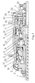
- Fig. 1 shows a half section through a power shift hub gear with a separate Pawl carrier.
- This shift hub has a mountain gear with a reduction, a direct gear with the same driver and hub sleeve speed and an overdrive with a corresponding translation.
- the hub axle 1 is attached to the bicycle frame on both sides.
- the hub sleeve 2 is supported by roller bearings on a fixed end shield 3 and the one that is also mounted Driver 4 from.
- a planetary gear is located between the driver 4 and the hub sleeve 2 consisting of an axially fixed sun gear 5, a planet carrier 6, planetary gears 7 and a ring gear 8.
- the different gears are switched on and off by a spring-coupled switching element 9 switched by the hollow hub axle 1.
- the one driven by a sprocket Driver 4 has two drive segments, one of which is the Take control part 10 rotatably and on the other hand the pawl carrier 11 via Take backlash and carry.
- On the latch bracket 11 are sprung on the circumference Drive pawls and brake pawls arranged, each of the control part 10 in the driving contour on the ring gear 8 can be controlled.
- On the inside diameter of the Pawl carrier 11 are spring-loaded transmission pawls 12 attached by the spring-loaded switching sleeve 13 into the driving contour on the coupling piece 14 is turned on or off.
- the spring-loaded coupling piece 14 is axially displaceable but always non-rotatably connected to the planet carrier 6 and transmits the force to the planet carrier in the controlled state.
- the planet gear carrier 6 has on the end shield side via a screw thread that a Axial displacement of the brake cone 17 allows, causing the brake jacket 18 in cooperation with another cone on the bearing plate 3 against the Brake cylinder 19 is pressed.
- the brake cone 17 has spring-loaded springs Pawls 20, which are always in the corresponding driving contour on the hub shell intervene or be overtaken by the driving contour.
- the switching element 9 is in the direction of the sun gear 5 postponed. This can only take place when the force applied to the switching element 9 Spring coupling is less than the biasing force on the switching sleeve 13.
- the Switching sleeve 13 moves the coupling piece 14 and the spacer sleeve 21 and thus the switching element 9 in the direction of the sun gear 5.
- the starting contour 15 on the coupling piece 14 moves under the ring gear pawls 16 and controls them from the driving contour on the hub sleeve 2.
- the power flow runs from the driver 4 via the drive pawls of the pawl carrier 11 to the ring gear 8, via the planet gears 7 to the planet gear carrier 6, from there to the brake cone 17 and finally via the pawls 20 to the hub sleeve 2. If there is none for the gearbox shifting Switching readiness is present, so the switching work is briefly in the switching sleeve spring 22 temporarily stored until a favorable switching situation arises again.
- the shift element 9 is in the direction of the driver 4 pushed, the spacer sleeve 21 shifts the switching sleeve 13 against the pending spring force.
- the spring-loaded coupling piece 14 follows the retreating Switch sleeve 13 and gives the ring gear pawls 16 the opportunity in to pivot the driving contour on the hub sleeve 2.
- the flow of power runs from the driver 4 via the drive pawls of the pawl carrier 11 to the ring gear 8 and About the ring gear pawls 16 to the hub sleeve 2, the pawls 20 of the corresponding driving contour on the hub sleeve 2 overhauled. Should for the Shift operation on the part of the transmission is not ready to shift, so the Switching work temporarily stored in the spring in front of the switching element until a favorable switching situation arises again.
- the shifting element 9 will continue in the direction Driver 4 pushed, the spacer sleeve 21 moves the switching sleeve 13th against the pending spring force.
- the transmission pawls driven by the overhang collar 23 12 are released and swing into the driving contour on Coupling piece 14 a.
- the power flow runs from the driver 4 via the transmission pawls 12 of the jack carrier 11 to the coupling piece 14, from there on Planet carrier 6 and the planet gears 7 to the ring gear 8, where it from the ring gear pawls 16 is introduced into the hub sleeve 2.
- Be in this switch position the pawls 20 from the corresponding driving contour on the hub sleeve 2 outdated. Should not be ready for shifting on the part of the transmission the switching work is briefly in the spring in front of the switching element temporarily stored until a favorable switching situation arises again.
- the preloaded switching sleeve spring 22 acts on the switching sleeve 13 and moves this and the coupling piece 14 and the spacer 21 and thus the switching element 9 in the direction Sun gear 5.
- the switching sleeve 13 moves with its collar 24 under the Transmission pawls 12 and causes precentering if the pawls are not exactly positioned the transmission pawls 12 before being driven by the control contour 25 and are kept in the modulated state by the overrun collar 23. Should for the Shifting into direct gear on the part of the transmission is not ready to shift the switching work is temporarily stored in the switching sleeve spring, until a favorable switching situation arises again.
- the coaster brake process always takes place via the mountain gear ratio and is initiated by a reverse movement on the driver.
- the twists Driver 4 opposite the jack carrier 11.
- corresponding recesses are provided on the jack carrier 11, the necessary backlash for the control of the drive or brake pawls by the control part 10.
- the control part 10 seated on the driver in a manner fixed against relative rotation is opposite the pawl carrier 11 rotated, the drive pawls and Brake pawls of corresponding control profiles in the control part 10, the pawls partially encloses, reversed at the same time.
- the brake pawls engage on both sides effective driving contour on the ring gear 8.
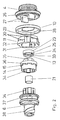
- Fig. 2 shows an exploded view with the essential, directly around the hub axis arranged gear components.
- the driver 4 takes on one side the gear on and has a raceway 26 for the rolling elements.
- the control part 10 is a molded plastic part and has control profiles 28 which are used for partly enclose the drive pawls and partly the brake pawls and with a relative movement of driver 4 and pawl carrier 11, the pawls each Turn on or off simultaneously according to the direction of rotation.
- the pawl carrier 11 is designed as a sintered molded part, without machining can be assembled.
- the circumference of the pawl receptacles 29 is opposite aligned drive and brake pawls provided. These handles are preloaded by a coil spring, which is an alternative to an all-round one Puncture of offset guide elements 30 is supported axially.
- At the Inner diameter of the pawl carrier 11 are in different circumferential sections on the one hand, recesses with the twist stops 31 for receiving the driving segments 27 and the other receiving troughs 32 for in the direction of the coupling piece 14 acting transmission pawls provided.
- the transmission jacks are sprung by a snap ring and axially fixed, as the snap ring attaches itself can support corresponding guide edges, not shown here.
- the shift sleeve 13 is a sintered molded part and is on the hub axle by means of a Longitudinal guide 33 rotatably guided.
- the start-up collar 24 takes over a possibly required one Pre-center the transmission pawls before moving from a cam Control contour 25 are controlled and then in this position by the thrust collar 23 are held.
- the switching sleeve 13 is in by the switching sleeve spring Biased towards the planet carrier 6 and via the spacer 21 from Shifting element axially shifted.
- the coupling piece 14 is also designed as a sintered molded part and is always over a coupling toothing 34 is connected to the planet gear carrier 6 in a rotationally fixed manner.
- the In the engaged state transmission pawls lie on the driving teeth 35 on.
- Analogous to the switching sleeve there is a start-up contour 15 on the control cam on the circumference 36 is provided, which with a corresponding displacement of the coupling piece 14 reaches under the ring gear pawls and controls them.
- the planet gear carrier rotates around the hub axis 6 and forms on one Side of the planetary gear guide 37, the counterpart to the clutch teeth 34.
- the other side is the seat of the brake cone 17 with the screw thread 38 for the axial displacement of the brake cone 17 during the backward movement the driver 4.
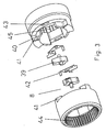
- Fig. 3 shows an exploded view of the ring gear 8 with the ring gear pawls, which as bolt-mounted sliding pawls 39 are formed.
- the ring gear is a sintered molded part designed and consists of two tool-falling halves, without cutting Post-processing is assembled without play after inserting the pawls become.
- the ring gear halves are matched to each other so that they are Support each other by means of radial guides 40 and twist stops 41.
- the Ring gear halves are not axially fixed to each other and are in the assembled state fixed by the planet carrier and the control section.
- the pawls 39 are of sheet springs 42, which are supported on the ring gear halves, biased and are stored with their bolt in opposite slots 43.
- the one Ring gear half has an internal toothing 44 which interacts with the planet gears, while in the other ring gear half the driving contour 45 for the drive or brake pawls are arranged.
- Fig. 4 shows the power flow in the various gear stages of the power shift hub gear.
- the power flow for the mountain gait is marked I and shown with a solid line.
- the switching element is in the left position, also marked with I. In this gear position, the driver speed is reduced, the hub sleeve consequently rotates more slowly than the driver driven by the pinion.
- the power flow in direct gear is marked II and is shown with a dash-dot line.
- the switching element is in the middle position, also marked II .
- the drive speed is passed on 1: 1 to the hub shell.
- the drive speed is translated into overdrive, the hub sleeve turns faster than the driver.
- the power flow is marked with III and is shown with a dashed line.
- the switching element is in the right position and is also marked III .
Landscapes
- Engineering & Computer Science (AREA)
- Chemical & Material Sciences (AREA)
- Combustion & Propulsion (AREA)
- Transportation (AREA)
- Mechanical Engineering (AREA)
- Structure Of Transmissions (AREA)
- Retarders (AREA)
Abstract
Description
- Fig. 1
- zeigt den Halbschnitt durch ein Nabengetriebe mit separatem Klinkenträger
- Fig. 2
- zeigt eine Explosionszeichnung mit den wesentlichen Getriebebauteilen
- Fig. 3
- zeigt eine Explosionszeichnung vom Hohlrad mit angefederten bolzengelagerten Verschiebeklinken
- Fig. 4
- zeigt den Kraftfluß in den verschiedenen Gangstufen
- 1
- Nabenachse
- 2
- Nabenhülse
- 3
- Lagerschild
- 4
- Antreiber
- 5
- Sonnenrad
- 6
- Planetenradträger
- 7
- Planetenrad
- 8
- Hohlrad
- 9
- Schaltelement
- 10
- Steuerteil
- 11
- Klinkenträger
- 12
- Übertragungsklinken
- 13
- Schalthülse
- 14
- Kupplungsstück
- 15
- Anlaufkontur
- 16
- Hohlradklinken
- 17
- Bremskonus
- 18
- Bremsmantel
- 19
- Bremszylinder
- 20
- Sperrklinken
- 21
- Distanzbuchse
- 22
- Schalthülsenfeder
- 23
- Auflaufbund
- 24
- Anlaufbund
- 25
- Steuerkontur
- 26
- Laufbahn
- 27
- Mitnahmesegment
- 28
- Steuerprofil
- 29
- Klinkenaufnahme
- 30
- Führungselement
- 31
- Verdrehanschlag
- 32
- Aufnahmemulde
- 33
- Längsführung
- 34
- Kupplungsverzahnung
- 35
- Mitnahmezahn
- 36
- Aussteuernocken
- 37
- Planetenradführung
- 38
- Schraubengewinde
- 39
- Verschiebeklinken
- 40
- Radialführung
- 41
- Verdrehanschlag
- 42
- Blechfedern
- 43
- Langloch
- 44
- Innenverzahnung
- 45
- Mitnahmekontur
Claims (34)
- Lastschaltbare Mehrgangnabe, insbesondere für Fahrräder, bestehend aus einer Nabenhülse 2, einer feststehenden Nabenachse 1, einem Schaltelement 9, einem gelagerten Antreiber 4, einem Planetenradgetriebe mit Planetenradträger 6, Planeterirädern 7 und Hohlrad 8, einem zwischen Antreiber 4 und Planetenradträger 6 angeordneten Kupplungsstück 14 sowie Klinken zur Kraftübertragung in verschiedenen Betriebs- bzw. Schaltstellungen,
dadurch gekennzeichnet, dass die Klinken zur Weiterleitung des Kraftflusses, sowohl der Antriebskraft, als auch der Bremskraft, nach außen an das Hohlrad 8 bzw. nach innen an das Kupplungsstück 14, gemeinsam in einem separaten Klinkenträger 11 angeordnet sind. - Lastschaltbare Mehrgangnabe nach Anspruch 1,
dadurch gekennzeichnet, dass Antreiber 4 und Klinkenträger 11 durch mindestens ein Mitnahmesegment 27, das ein Verdrehspiel zuläßt, verbunden sind. - Lastschaltbare Mehrgangnabe nach Anspruch 2,
dadurch gekennzeichnet, dass der Klinkenträger 11 auf mindestens zwei Mitnahmesegmenten 27 des Antreibers 4, die axial in den Klinkenträger 11 hineinragen, gelagert ist und in beiden Drehrichtungen bewegt werden kann und dass ein Verdrehspiel zwischen Mitnahmesegmente 27 und Verdrehanschläge 31 im Klinkenträger 11 vorgesehen ist. - Lastschaltbare Mehrgangnabe nach Anspruch 1,
dadurch gekennzeichnet, dass die Klinken zur Kopplung von Klinkenträger 11 und Hohlrad 8 am Umfang des Klinkenträgers 11 und die Klinken zur Kopplung von Klinkenträger 11 und Kupplungsstück 14 am Innendurchmesser des Klinkenträgers 11 angeordnet sind. - Lastschaltbare Mehrgangnabe nach Anspruch 4,
dadurch gekennzeichnet, dass die Klinken am Klinkenträger 11 unter Federvorspannung stehen, verursacht durch Federelemente z. B. Schraubenfeder oder Sprengring, so dass die Klinken, wenn nicht daran gehindert, radial vom Klinkenträger 11 weg schwenken. - Lastschaltbare Mehrgangnabe nach den Ansprüchen 4 und 5,
dadurch gekennzeichnet, dass die Klinken zur Kopplung von Klinkenträger 11 und Hohlrad 8 mittels eines, drehfest mit dem Antreiber 4 verbundenen Steuerteils 10 sowie einem entsprechend angeordneten Federelement, insbesondere Schraubenfeder, drehrichtungsabhängig in die Mitnahmekontur 45 des Hohlrades hinein oder heraus bewegt werden. - Lastschaltbare Mehrgangnabe nach Anspruch 6,
dadurch gekennzeichnet, dass sich Steuerteil 10 und Antreiber 4 relativ zum Klinkenträger 11 verdrehen und somit die federvorgespannten Klinken drehrichtungsabhängig in einen Freiraum bzw. zum Steuernocken 28 am Steuerteil 10 radial nach außen schwenken können oder nach innen gedrückt werden, wenn das Steuerteil 10 weiter gedreht wird und die Klinken über den Steuernocken 28 nach innen bewegt werden. - Lastschaltbare Mehrgangnabe nach den Ansprüchen 6 und 7,
dadurch gekennzeichnet, dass am Steuerteil 10 eine, mehrere Freiräume bzw. Steuerprofil 28 bildende Kontur zum radialen Ein- bzw. Auskoppeln der Klinken vorgesehen ist und dass diese Kontur die Klinken am Umfang teilweise axial umschließen. - Lastschaltbare Mehrgangnabe nach den Ansprüchen 6 bis 8,
dadurch gekennzeichnet, dass das Steuerteil 10 als Formteil, insbesondere als Kunststoffformteil gestaltet ist und aus einem maßhaltigen und wärmebeständigen Werkstoff besteht und zwischen Antreiber 4 und Klinkenträger 11 angeordnet ist.. - Lastschaltbare Mehrgangnabe nach den Ansprüchen 6 und 7,
dadurch gekennzeichnet, dass mindestens eine Klinke am Umfang des Klinkenträgers 11 angeordnet sind, die vom Steuerteil 10 gesteuert beim Vorwärtsdrehen in Eingriff gelangt sowie mindestens eine Klinke, die beim Rückwärtsdrehen in Funktion tritt, insbesondere dann, wenn die Rücktrittbremse wirksam werden soll, wobei der Ein- bzw. Aussteuervorgang jeweils gleichzeitig erfolgt. - Lastschaltbare Mehrgangnabe nach Anspruch 10,
dadurch gekennzeichnet, dass der Klinkenträger 11 als Formteil, insbesondere Sinterformteil oder Umformteil gestaltet ist und keine spanenden Bearbeitungen erforderlich sind. - Lastschaltbare Mehrgangnabe nach Anspruch 11,
dadurch gekennzeichnet, dass die axiale Fixierung der Federelemente, vorzugsweise Schraubenfeder oder Sprengring, zum Halten und Vorspannen der Klinken durch axial und radial versetzte Führungselemente 30 am Umfang bzw. am Innendurchmesser des Klinkenträgers 11, gewährleistet wird. - Lastschaltbare Mehrgangnabe nach den Ansprüchen 1 bis 5,
dadurch gekennzeichnet, dass die Klinken zur Kopplung von Klinkenträger 11 und Kupplungsstück-14 länger sind, als die Mitnahmezähne 35 am Kupplungsstück 14 und dass die angefederten Klinken mittels einer, drehfest mit der Nabenachse 1 verbundenen, axial verschiebbaren Schalthülse 13 aus den Mitnahmezähnen 35 des Kupplungsstückes 14 heraus bewegt werden können. - Lastschaltbare Mehrgangnabe, insbesondere für Fahrräder, bestehend aus einer Nabenhülse 2, einer feststehenden Nabenachse 1, einem Schaltelement 9, einem gelagerten Antreiber 4, einem Planetenradgetriebe mit Planetenradträger 6, Planetenrädern 7 und Hohlrad 8, einem zwischen Antreiber 4 und Planetenradträger 6 angeordneten Kupplungsstück 14 sowie Klinken zur Kraftübertragung in verschiedenen Betriebs- bzw. Schaltstellungen,
dadurch gekennzeichnet, dass zwischen Schalthülse 13 und Schaltelement 9 eine Distanzbuchse 21 angeordnet ist und die Schalthülse 13 von einer Schalthülsenfeder 22, insbesondere Druckfeder in Richtung Schaltelement 9 vorgespannt ist. - Lastschaltbare Mehrgangnabe nach Anspruch 14,
dadurch gekennzeichnet, dass der axiale Abstand der Schalthülse 13 zum Schaltelement 9 von einer Distanzbuchse 21 gewährleistet wird und die Länge der Distanzbuchse 21 größer ist als die Länge der gegenüberliegenden Innenmantelfläche am Kupplungsstück 14. - Lastschaltbare Mehrgangnabe nach den Ansprüchen 14 und 15,
dadurch gekennzeichnet, dass die Distanzbuchse 21 bei einer Schaltbewegung des Schaltelementes 9 in Richtung Planetenrad 7, bereits eine gleichgerichtete Verschiebung der vorgespannten Schalthülse 13 ermöglicht, während die nach innen gerichteten Klinken am Klinkenträger 11 noch in die Mitnahmezähne 35 des Kupplungsstückes 14 eingreifen. - Lastschaltbare Mehrgangnabe nach den Ansprüchen 14 bis 16,
dadurch gekennzeichnet, dass die Schalthülse 13 mit einer Steuerkontur 25 ausgestattet ist, um bei axialer Verschiebung die Klinken aus den Mitnahmezähnen 35 am Kupplungsstück 14 auszusteuern anschließend wird auch das nunmehr lastfreie Kupplungsstück 14 von der Schalthülse 13 in Richtung Planetenrad 7 verschoben. - Lastschaltbare Mehrgangnabe nach Anspruch 17,
dadurch gekennzeichnet, dass die Schalthülse 13 mit einem Anlaufbund 24, dessen Durchmesser dem Fußkreisdurchmesser der Mitnahmezähne 35 am Kupplungsstück 14 entspricht und das Vorzentrieren der Klinken gewährleistet. - Lastschaltbare Mehrgangnabe nach Anspruch 18,
dadurch gekennzeichnet, dass der Anlaufbund 24 der Schalthülse 13 konisch verläuft, wobei der Anfangsdurchmesser geringfügig kleiner und der Enddurchmesser geringfügig größer ist als der Fußkreisdurchmesser der Mitnahmezähne 35 am Kupplungsstück. - Lastschaltbare Mehrgangnabe nach Anspruch 17,
dadurch gekennzeichnet, dass die Schalthülse 13 mit Nocken ausgestattet ist, die mit einer Steuerkontur 25 zum Aussteuern der Klinken versehen sind und dass die Schalthülse 13 als Formteil, insbesondere Sinterformteil oder Umformteil gestaltet ist. - Lastschaltbare Mehrgangnabe nach den Ansprüchen 16 und 17,
dadurch gekennzeichnet, dass bei einer weiteren Schaltbewegung des Schaltelementes 9 in Richtung Planetenrad 7, das Kupplungsstück 14 von der vorgespannten Schalthülse 13 gleichgerichtet verschoben wird, um mit einer Anlaufkontur 15 am Kupplungsstück 14, die im Hohlrad 8 gelagerten Hohlradklinken 16 bzw. Verschiebeklinken 39 aus der Kontur an der Nabenhülse 2 heraus zu steuern. - Lastschaltbare Mehrgangnabe nach den Ansprüchen 1 bis 4,
dadurch gekennzeichnet, dass das Kupplungsstück 14 vom Antreiber 4 aus über mindestens eine Klinke am Klinkenträger 11, die in einen Mitnahmezahn 35 am Kupplungsstück 14 eingreift, angetrieben werden kann und dass das Kupplungsstück 14 in allen Schaltstellungen drehfest aber axial verschiebbar mit dem Planetenradträger 6 verbunden ist. - Lastschaltbare Mehrgangnabe nach Anspruch 22,
dadurch gekennzeichnet, dass das Kupplungsstück 14 am Umfang mit einer Anlaufkontur 15 ausgestattet ist, die bei Verschiebung des Kupplungsstückes 14 in Richtung Planetenrad 7, die im Hohlrad 8 gelagerten und in die Kontur an der Nabenhülse 2 eingreifenden Hohlradklinken 16 bzw. Verschiebeklinken 39 aussteuert. - Lastschaltbare Mehrgangnabe nach den Ansprüchen 22 und 23,
dadurch gekennzeichnet, dass das Kupplungsstück 14 als Formteil, insbesondere Sinterformteil oder Umformteil gestaltet ist. - Lastschaltbare Mehrgangnabe, insbesondere für Fahrräder, bestehend aus einer Nabenhülse 2, einer feststehenden Nabenachse 1, einem Schaltelement 9, einem gelagerten Antreiber 4, einem Planetenradgetriebe mit Planetenradträger 6, Planetenrädern 7 und Hohlrad 8, einem zwischen Antreiber 4 und Planetenradträger 6 angeordneten Kupplungsstück 14 sowie Klinken zur Kraftübertragung in verschiedenen Betriebs- bzw. Schaltstellungen,
dadurch gekennzeichnet, dass das Hohlrad 8 zur Kopplung mit der Nabenhülse 2 mit Hohlradklinken 16 bzw. Verschiebeklinken 39 ausgestattet ist und im Bereich dieser Klinken geteilt ist. - Lastschaltbare Mehrgangnabe nach Anspruch 25,
dadurch gekennzeichnet, dass die Klinken als bolzengelagerte Verschiebeklinken 39 ausgebildet sind, um einer Getriebeverspannung nach einem Rücktrittbremsvorgang entgegenzuwirken und dass in den Hohlradhälften gegenüberliegende Langlöcher 43 zur Führung der Bolzen angeordnet sind. - Lastschaltbare Mehrgangnabe nach den Ansprüchen 25 und 26,
dadurch gekennzeichnet, dass die Verschiebeklinken 39 jeweils von mindestens einer Feder, vorzugsweise Blechfeder 42 nach außen vorgespannt sind und dass sich die Blechfedern an den Hohlradhälften abstützen. - Lastschaltbare Mehrgangnabe nach den Ansprüchen 25 bis 27,
dadurch gekennzeichnet, dass die Hohlradhälften im gegenseitigen Kontaktbereich über eine entsprechend aufeinander abgestimmte Formgebung verfügen, bestehend aus Radialführung 40 und Verdrehanschlag 41, um eine radiale und drehfeste Verbindung zu gewährleisten. - Lastschaltbare Mehrgangnabe nach Anspruch 28,
dadurch gekennzeichnet, dass die Hohlradhälften nur von den angrenzenden Getriebebauteilen axial fixiert werden und dass die Hohlradhälften als Formteile, insbesondere Sinterformteile oder Umformteile gestaltet sind. - Lastschaltbare Mehrgangnabe nach einem oder mehreren vorhergehenden Ansprüchen,
dadurch gekennzeichnet, dass die Gangwahl über ein- bzw. ausgesteuerte Klinken erfolgt, wobei der Kraftfluß im Berggang vom Antreiber 4 bzw. vom angetriebenen Klinkenträger 11 über Antriebsklinken an das Hohlrad 8, von dort über die Planetenräder 7 auf den Planetenradträger 6 und über Sperrklinken 20 am Bremskonus 17, der vom Planetenradträger 6 angetrieben wird, an die Nabenhülse 2 weitergeleitet wird, hierbei sind die Übertragungsklinken 12 zum Kupplungsstück 14 und die Hohlradklinken 16 bzw. Verschiebeklinken 39 vom Hohlrad 8 zur Nabenhülse 2 ausgesteuert. - Lastschaltbare Mehrgangnabe nach einem oder mehreren vorhergehenden Ansprüchen,
dadurch gekennzeichnet, dass die Gangwahl über ein- bzw. ausgesteuerte Klinken erfolgt, wobei der Kraftfluß im direkten Gang vom Antreiber 4 bzw. vom angetriebenen Klinkenträger 11 über Antriebsklinken an das Hohlrad 8 und von dort über die Hohlradklinken 16 bzw. Verschiebeklinken 39 an die Nabenhülse 2 weitergeleitet wird, hierbei sind die Übertragungsklinken 12 zum Kupplungsstück 14 ausgesteuert und die Sperrklinken 20 vom Bremskonus 17 zur Nabenhülse 2 werden überholt. - Lastschaltbare Mehrgangnabe nach einem oder mehreren vorhergehenden Ansprüchen,
dadurch gekennzeichnet, dass die Gangwahl über ein- bzw. ausgesteuerte Klinken erfolgt, wobei der Kraftfluß im Schnellgang vom Antreiber 4 bzw. vom angetriebenen Klinkenträger 11 mittels Übertragungsklinken 12 an das Kupplungsstück 14, dann zum Planetenradträger 6 und über die Planetenräder 7 auf das Hohlrad 8 und schließlich über Hohlradklinken 16 bzw. die Verschiebeklinken 39 im Hohlrad 8 an die Nabenhülse 2 weitergeleitet wird, hierbei werden die Sperrklinken 20 am Bremskonus 17 von der entsprechenden Kontur in der Nabenhülse 2 und die Antriebsklinken am Klinkenträger 11 von der Mitnahmekontur am Hohlrad überholt. - Lastschaltbare Mehrgangnabe nach einem oder mehreren vorhergehenden Ansprüchen,
dadurch gekennzeichnet, dass die Rücktrittbremse stets in der Berggangübersetzung wirkt und über gleichzeitig ein- bzw. ausgesteuerte Klinken am Klinkenträger 11 aktiviert wird, wobei die Bremsklinken durch Rückwärtsdrehen des Antreibers 4 und nach Überwindung eines Verdrehspieles zwischen Antreiber 4 und Klinkenträger 11 mittels Steuerprofil 28 am Steuerteil 10, an der Mitnahmekontur 45 am Hohlrad 8 zum Eingriff gebracht werden. - Lastschaltbare Mehrgangnabe nach Anspruch 33,
dadurch gekennzeichnet, dass die bei einer Rücktrittbremsung in das Hohlrad eingeleitete Rückdrehbewegung über die Planetenräder 7 auf den Planetenradträger 6 übertragen wird und dort in eine Bremsbewegung des Bremskonuses 17 oder anderer Bremsmittel umgeformt wird und dass die an der Nabenhülse 2 angreifenden Hohlradklinken 16 bzw. Verschiebeklinken 39 und die am Kupplungsstück 14 angreifenden Übertragungsklinken 12 beim Bremsvorgang von den entsprechenden Mitnahmekonturen überholt werden oder gerade ausgesteuert sind.
Applications Claiming Priority (2)
| Application Number | Priority Date | Filing Date | Title |
|---|---|---|---|
| DE10134842 | 2001-07-17 | ||
| DE10134842A DE10134842A1 (de) | 2001-07-17 | 2001-07-17 | Lastschaltbare Mehrgangnabe |
Publications (3)
| Publication Number | Publication Date |
|---|---|
| EP1277649A2 true EP1277649A2 (de) | 2003-01-22 |
| EP1277649A3 EP1277649A3 (de) | 2005-02-23 |
| EP1277649B1 EP1277649B1 (de) | 2008-06-25 |
Family
ID=7692152
Family Applications (1)
| Application Number | Title | Priority Date | Filing Date |
|---|---|---|---|
| EP02014742A Expired - Lifetime EP1277649B1 (de) | 2001-07-17 | 2002-07-04 | Lastschaltbare Mehrgangnabe |
Country Status (5)
| Country | Link |
|---|---|
| US (1) | US6692400B2 (de) |
| EP (1) | EP1277649B1 (de) |
| CN (1) | CN1325289C (de) |
| DE (2) | DE10134842A1 (de) |
| TW (1) | TW589269B (de) |
Cited By (1)
| Publication number | Priority date | Publication date | Assignee | Title |
|---|---|---|---|---|
| EP3715676A4 (de) * | 2017-11-23 | 2021-07-28 | Mbi Co. Ltd. | Vorrichtung zur unterstützung der schaltbetätigung und in die nabe eingebettetes getriebe damit |
Families Citing this family (20)
| Publication number | Priority date | Publication date | Assignee | Title |
|---|---|---|---|---|
| EP1452437B2 (de) † | 2003-02-28 | 2009-06-17 | Shimano Inc. | Antriebsnabe für ein Fahrrad |
| CN100439759C (zh) * | 2004-03-22 | 2008-12-03 | 通用汽车公司 | 具有由相同部件组装的机电模块的混合式车用传动装置 |
| DE102004014239A1 (de) * | 2004-03-24 | 2005-10-06 | Sram Deutschland Gmbh | Bremseinrichtung für eine Mehrgangnabe |
| DE102004034113A1 (de) * | 2004-07-15 | 2006-02-09 | Sram Deutschland Gmbh | Getriebenabe mit Bremseinrichtung |
| DE102005003056A1 (de) * | 2005-01-22 | 2006-07-27 | Sram Deutschland Gmbh | Schaltbewegungsübertragung in ein Fahrradgetriebe |
| DE502006002194D1 (de) * | 2006-04-28 | 2009-01-08 | Shimano Kk | Mehrgangnabe mit Rücktrittbremse |
| US7621842B2 (en) * | 2007-02-14 | 2009-11-24 | Shimano Inc. | Bicycle hub assembly |
| DE102007021970A1 (de) | 2007-05-10 | 2008-11-13 | Sram Deutschland Gmbh | Mehrgangnabe mit Friktionskupplung für begrenzbare Schaltlasten |
| US7874955B2 (en) * | 2007-09-28 | 2011-01-25 | Patterson Bicycle Transmission, Llc | Bicycle transmission system |
| US8100810B2 (en) * | 2007-12-28 | 2012-01-24 | Shimano Inc. | Bicycle internal hub transmission with helical gear |
| US8162340B2 (en) * | 2008-12-31 | 2012-04-24 | Sam Patterson | Spiral rotor chain shifting system |
| US8342553B2 (en) * | 2009-05-27 | 2013-01-01 | Patterson Bicycle Transmission Llc | Mounting method for bottom bracket planetary |
| DE102014208793A1 (de) | 2014-05-09 | 2015-11-12 | Zf Friedrichshafen Ag | Planetenradsatz |
| TWI606957B (zh) * | 2015-01-05 | 2017-12-01 | Internal transmission control mechanism | |
| US10041567B2 (en) * | 2015-03-20 | 2018-08-07 | Jen-chih Liu | Driving control system of internal clutch |
| US20190242459A1 (en) * | 2018-02-07 | 2019-08-08 | Jen-chih Liu | Control assembly of an internal clutch |
| TWI724652B (zh) * | 2019-11-27 | 2021-04-11 | 日馳企業股份有限公司 | 自行車變速裝置 |
| US20220213938A1 (en) * | 2020-08-03 | 2022-07-07 | Jen-chih Liu | Interior clutch-used control mechanism |
| US20220205494A1 (en) * | 2020-08-03 | 2022-06-30 | JEN-CHIH Lyang LIU | Interior clutch-used control mechanism |
| US20220221012A1 (en) * | 2020-08-03 | 2022-07-14 | Jen-chih Liu | Interior clutch-used control mechanism |
Citations (2)
| Publication number | Priority date | Publication date | Assignee | Title |
|---|---|---|---|---|
| DE2937126C2 (de) | 1978-09-13 | 1983-09-29 | Shimano Industrial Co., Ltd., Sakai, Osaka | Steuermechanismus für eine Fahrrad-Schaltnabe |
| DE3443592C2 (de) | 1983-11-29 | 1989-08-10 | Shimano Industrial Co., Ltd., Sakai, Osaka, Jp |
Family Cites Families (19)
| Publication number | Priority date | Publication date | Assignee | Title |
|---|---|---|---|---|
| DE2209535C2 (de) * | 1972-02-29 | 1974-01-17 | Fichtel & Sachs Ag, 8720 Schweinfurt | Mehrgangübersetzungsnabe mit Rücktrittbremse |
| DE2232741C2 (de) * | 1972-07-04 | 1974-07-18 | Fichtel & Sachs Ag, 8720 Schweinfurt | Schaltzuglose Mehrgang-Nabe fm Fahrräder mit vereinfachter Achsfunktion |
| DE8228602U1 (de) * | 1982-10-12 | 1983-02-03 | Fichtel & Sachs Ag, 8720 Schweinfurt | Sperrklinkentraeger zu einem freilaufgesperre, insbesondere fahrraeder od. dgl. |
| DE3407164C2 (de) * | 1983-03-05 | 1993-11-18 | Fichtel & Sachs Ag | Mehrgang-Antriebsnabe für Fahrräder |
| DE3448489C2 (de) * | 1984-11-02 | 1995-02-02 | Fichtel & Sachs Ag | Mehrgang-Nabe für Fahrräder o. dgl. |
| DE3440067A1 (de) * | 1984-11-02 | 1986-05-07 | Fichtel & Sachs Ag, 8720 Schweinfurt | Mehrgangnabe fuer fahrraeder oder dergleichen |
| GB8713238D0 (en) * | 1987-06-05 | 1987-07-08 | Sturmey Archer Ltd | Epicyclic change-speed gear mechanism |
| DE3732977A1 (de) * | 1987-09-30 | 1989-04-20 | Fichtel & Sachs Ag | Mehrgangnabe |
| DE3908989A1 (de) * | 1989-03-18 | 1990-09-20 | Sinterstahl Gmbh | Verfahren zur herstellung einer schalt- oder schiebemuffe fuer kfz-getriebe |
| DE4229023C2 (de) * | 1992-09-01 | 1995-02-16 | Fichtel & Sachs Ag | Schalteinrichtung für Mehrgangnabe |
| DE4313558A1 (de) * | 1993-04-26 | 1994-10-27 | Fichtel & Sachs Ag | Mehrgang-Fahrradnabe |
| DE4402344C1 (de) * | 1994-01-27 | 1995-03-16 | Fichtel & Sachs Ag | Steuereinrichtung für Klinkengesperre für Fahrrad-Mehrgangantriebsnaben |
| KR970042080A (ko) * | 1995-12-30 | 1997-07-24 | 마재열 | 자전거의 주행장치 |
| US6039671A (en) * | 1999-02-09 | 2000-03-21 | Kun Teng Industry Co., Ltd. | Multi-speed drive hub for a bicycle |
| DE10014265C5 (de) * | 1999-06-17 | 2012-04-26 | Sram Deutschland Gmbh | Schalteinrichtung für eine Mehrgangnabe für ein Fahrrad |
| EP1060980B1 (de) * | 1999-06-17 | 2004-03-17 | SRAM Deutschland GmbH | Schalteinrichtung für eine Mehrgangnabe für ein Fahrrad |
| DE10061181A1 (de) * | 1999-12-24 | 2001-06-28 | Sram De Gmbh | Mehrgangnabe für ein Fahrrad |
| US6607465B1 (en) * | 2000-03-10 | 2003-08-19 | Shimano, Inc. | Bicycle hub transmission with a guiding member for a sun gear |
| US6558288B2 (en) * | 2001-05-18 | 2003-05-06 | Shimano, Inc. | Internal transmission device with automatic shift mechanism for a bicycle |
-
2001
- 2001-07-17 DE DE10134842A patent/DE10134842A1/de not_active Withdrawn
-
2002
- 2002-07-04 EP EP02014742A patent/EP1277649B1/de not_active Expired - Lifetime
- 2002-07-04 DE DE50212400T patent/DE50212400D1/de not_active Expired - Lifetime
- 2002-07-10 TW TW091115306A patent/TW589269B/zh not_active IP Right Cessation
- 2002-07-16 CN CNB021407452A patent/CN1325289C/zh not_active Expired - Fee Related
- 2002-07-17 US US10/064,474 patent/US6692400B2/en not_active Expired - Fee Related
Patent Citations (2)
| Publication number | Priority date | Publication date | Assignee | Title |
|---|---|---|---|---|
| DE2937126C2 (de) | 1978-09-13 | 1983-09-29 | Shimano Industrial Co., Ltd., Sakai, Osaka | Steuermechanismus für eine Fahrrad-Schaltnabe |
| DE3443592C2 (de) | 1983-11-29 | 1989-08-10 | Shimano Industrial Co., Ltd., Sakai, Osaka, Jp |
Cited By (1)
| Publication number | Priority date | Publication date | Assignee | Title |
|---|---|---|---|---|
| EP3715676A4 (de) * | 2017-11-23 | 2021-07-28 | Mbi Co. Ltd. | Vorrichtung zur unterstützung der schaltbetätigung und in die nabe eingebettetes getriebe damit |
Also Published As
| Publication number | Publication date |
|---|---|
| US20030017905A1 (en) | 2003-01-23 |
| US6692400B2 (en) | 2004-02-17 |
| CN1397438A (zh) | 2003-02-19 |
| DE50212400D1 (de) | 2008-08-07 |
| EP1277649B1 (de) | 2008-06-25 |
| CN1325289C (zh) | 2007-07-11 |
| DE10134842A1 (de) | 2003-02-06 |
| EP1277649A3 (de) | 2005-02-23 |
| TW589269B (en) | 2004-06-01 |
Similar Documents
| Publication | Publication Date | Title |
|---|---|---|
| EP1277649B1 (de) | Lastschaltbare Mehrgangnabe | |
| DE60119808T2 (de) | Fahrradantriebsnabe | |
| DE2940841C2 (de) | ||
| EP0528383B1 (de) | Antriebsnabe für ein Fahrzeug | |
| EP2617639B1 (de) | Fahrradgetriebe, insbesondere in Form einer Mehrgang-Getriebenabe | |
| DE2819471C2 (de) | Freilaufnabe | |
| EP0910530B1 (de) | Mehrgang-getriebe für fahrräder | |
| EP3759372B1 (de) | Kupplungsanordnung und getriebeeinheit für ein per muskelkraft antreibbares fahrzeug | |
| EP2327617B1 (de) | Mehrgang-Getriebenabe für Fahrräder | |
| EP0554874B1 (de) | Mehrgang-Antriebsnabe für Fahrräder | |
| DE102008064514A1 (de) | Getriebeeinheit | |
| WO2008089932A1 (de) | Getriebeeinheit | |
| EP3509935B1 (de) | Antriebsanordnung und fahrzeug | |
| AT391668B (de) | Mehrgang-antriebsnabe mit wenigstens drei gaengen fuer fahrraeder | |
| DE102016207035A1 (de) | Antriebsanordnung und Fahrzeug | |
| DE102010049438A1 (de) | Betätigungsmechanik für eine Mehrfach-Fahrradgetriebenabe | |
| EP0693419B1 (de) | Mehrgang-Antriebsnabe mit mehr als 3 Gängen für ein Fahrrad | |
| EP3209544B1 (de) | Koaxial angeordnetes reibringgetriebe für ein mit motorkraft und/oder pedalkraft betreibbares fahrzeug | |
| DD212702A5 (de) | Nabe fuer ein zweiradfahrzeug | |
| DE102022107408B3 (de) | Freilaufeinrichtung sowie Kupplungsanordnung mit der Freilaufeinrichtung | |
| DE69702087T3 (de) | Antriebsnabe mit Bremse für ein Fahrrad | |
| DE2232741C2 (de) | Schaltzuglose Mehrgang-Nabe fm Fahrräder mit vereinfachter Achsfunktion | |
| EP2426043B1 (de) | Fahrradnabengetriebe | |
| DE102023211468B3 (de) | Kupplungseinrichtung und Getriebeschaltung für ein Fahrrad mit einer solchen Kupplungseinrichtung | |
| DE1092791B (de) | Mehrganguebersetzungsnabe fuer Fahr- und Motorraeder |
Legal Events
| Date | Code | Title | Description |
|---|---|---|---|
| PUAI | Public reference made under article 153(3) epc to a published international application that has entered the european phase |
Free format text: ORIGINAL CODE: 0009012 |
|
| AK | Designated contracting states |
Kind code of ref document: A2 Designated state(s): AT BE BG CH CY CZ DE DK EE ES FI FR GB GR IE IT LI LU MC NL PT SE SK TR |
|
| AX | Request for extension of the european patent |
Free format text: AL;LT;LV;MK;RO;SI |
|
| PUAL | Search report despatched |
Free format text: ORIGINAL CODE: 0009013 |
|
| AK | Designated contracting states |
Kind code of ref document: A3 Designated state(s): AT BE BG CH CY CZ DE DK EE ES FI FR GB GR IE IT LI LU MC NL PT SE SK TR |
|
| AX | Request for extension of the european patent |
Extension state: AL LT LV MK RO SI |
|
| 17P | Request for examination filed |
Effective date: 20050317 |
|
| AKX | Designation fees paid |
Designated state(s): DE FR NL |
|
| 17Q | First examination report despatched |
Effective date: 20061205 |
|
| GRAP | Despatch of communication of intention to grant a patent |
Free format text: ORIGINAL CODE: EPIDOSNIGR1 |
|
| GRAS | Grant fee paid |
Free format text: ORIGINAL CODE: EPIDOSNIGR3 |
|
| GRAA | (expected) grant |
Free format text: ORIGINAL CODE: 0009210 |
|
| AK | Designated contracting states |
Kind code of ref document: B1 Designated state(s): DE FR NL |
|
| REF | Corresponds to: |
Ref document number: 50212400 Country of ref document: DE Date of ref document: 20080807 Kind code of ref document: P |
|
| PLBE | No opposition filed within time limit |
Free format text: ORIGINAL CODE: 0009261 |
|
| STAA | Information on the status of an ep patent application or granted ep patent |
Free format text: STATUS: NO OPPOSITION FILED WITHIN TIME LIMIT |
|
| 26N | No opposition filed |
Effective date: 20090326 |
|
| REG | Reference to a national code |
Ref country code: FR Ref legal event code: PLFP Year of fee payment: 14 |
|
| PGFP | Annual fee paid to national office [announced via postgrant information from national office to epo] |
Ref country code: FR Payment date: 20150626 Year of fee payment: 14 |
|
| PGFP | Annual fee paid to national office [announced via postgrant information from national office to epo] |
Ref country code: NL Payment date: 20150721 Year of fee payment: 14 |
|
| REG | Reference to a national code |
Ref country code: NL Ref legal event code: MM Effective date: 20160801 |
|
| PG25 | Lapsed in a contracting state [announced via postgrant information from national office to epo] |
Ref country code: FR Free format text: LAPSE BECAUSE OF NON-PAYMENT OF DUE FEES Effective date: 20160801 Ref country code: NL Free format text: LAPSE BECAUSE OF NON-PAYMENT OF DUE FEES Effective date: 20160801 |
|
| REG | Reference to a national code |
Ref country code: FR Ref legal event code: ST Effective date: 20170331 |
|
| PGFP | Annual fee paid to national office [announced via postgrant information from national office to epo] |
Ref country code: DE Payment date: 20170731 Year of fee payment: 16 |
|
| REG | Reference to a national code |
Ref country code: DE Ref legal event code: R119 Ref document number: 50212400 Country of ref document: DE |
|
| PG25 | Lapsed in a contracting state [announced via postgrant information from national office to epo] |
Ref country code: DE Free format text: LAPSE BECAUSE OF NON-PAYMENT OF DUE FEES Effective date: 20190201 |