EP1277649A2 - Transmission pour moyeu à plusieurs vitesses - Google Patents
Transmission pour moyeu à plusieurs vitesses Download PDFInfo
- Publication number
- EP1277649A2 EP1277649A2 EP02014742A EP02014742A EP1277649A2 EP 1277649 A2 EP1277649 A2 EP 1277649A2 EP 02014742 A EP02014742 A EP 02014742A EP 02014742 A EP02014742 A EP 02014742A EP 1277649 A2 EP1277649 A2 EP 1277649A2
- Authority
- EP
- European Patent Office
- Prior art keywords
- pawls
- ring gear
- gear
- coupling piece
- carrier
- Prior art date
- Legal status (The legal status is an assumption and is not a legal conclusion. Google has not performed a legal analysis and makes no representation as to the accuracy of the status listed.)
- Granted
Links
- 230000005540 biological transmission Effects 0.000 title claims abstract description 27
- 230000008878 coupling Effects 0.000 claims description 65
- 238000010168 coupling process Methods 0.000 claims description 65
- 238000005859 coupling reaction Methods 0.000 claims description 65
- 230000033001 locomotion Effects 0.000 claims description 15
- 238000006073 displacement reaction Methods 0.000 claims description 13
- 125000006850 spacer group Chemical group 0.000 claims description 12
- 238000000034 method Methods 0.000 claims description 6
- 239000002184 metal Substances 0.000 claims description 3
- 238000003754 machining Methods 0.000 claims description 2
- 239000002991 molded plastic Substances 0.000 claims description 2
- 230000006835 compression Effects 0.000 claims 1
- 238000007906 compression Methods 0.000 claims 1
- 239000003779 heat-resistant material Substances 0.000 claims 1
- 230000002349 favourable effect Effects 0.000 description 5
- 238000004519 manufacturing process Methods 0.000 description 5
- 238000013461 design Methods 0.000 description 2
- 239000004033 plastic Substances 0.000 description 2
- 238000012805 post-processing Methods 0.000 description 2
- 238000012546 transfer Methods 0.000 description 2
- 238000013519 translation Methods 0.000 description 2
- 239000000969 carrier Substances 0.000 description 1
- 238000005520 cutting process Methods 0.000 description 1
- 230000007547 defect Effects 0.000 description 1
- 230000005021 gait Effects 0.000 description 1
- 238000012432 intermediate storage Methods 0.000 description 1
- 238000000465 moulding Methods 0.000 description 1
- 238000005096 rolling process Methods 0.000 description 1
Images

Classifications
-
- B—PERFORMING OPERATIONS; TRANSPORTING
- B62—LAND VEHICLES FOR TRAVELLING OTHERWISE THAN ON RAILS
- B62M—RIDER PROPULSION OF WHEELED VEHICLES OR SLEDGES; POWERED PROPULSION OF SLEDGES OR SINGLE-TRACK CYCLES; TRANSMISSIONS SPECIALLY ADAPTED FOR SUCH VEHICLES
- B62M11/00—Transmissions characterised by the use of interengaging toothed wheels or frictionally-engaging wheels
- B62M11/04—Transmissions characterised by the use of interengaging toothed wheels or frictionally-engaging wheels of changeable ratio
- B62M11/14—Transmissions characterised by the use of interengaging toothed wheels or frictionally-engaging wheels of changeable ratio with planetary gears
- B62M11/16—Transmissions characterised by the use of interengaging toothed wheels or frictionally-engaging wheels of changeable ratio with planetary gears built in, or adjacent to, the ground-wheel hub
Definitions
- the present invention relates to a power shift transmission hub according to the Preamble of the main claim.
- Power shift transmissions have facilities that allow transmission elements, which are currently in the flow of power, to control with low switching force and control other gear elements.
- This control of gear elements, such as ring gear, planet carrier, driver and clutch component is preferably carried out via controllable, spring-loaded pawls.
- Such a ratchet control is already described in DE 2937126 C2 using a Two-wheel hub described.
- one is arranged in the axial direction and between two end positions, by means of a shift rod shiftable switching element a biased ratchet control member with a relatively low switching force against spring-loaded pawls moved.
- the pawl control element engages under the pawls and it swivels out of the corresponding ratchet teeth, even under load and thus interrupts the flow of power.
- a ratchet-controlled, power shiftable multi-speed gear hub with a pinion-bearing Driver mounted on a rigid hub axle and a planetary gear set is described in DE 3443592 C2.
- This shift hub points a planetary gear with a fixed sun gear, planet carrier with planet gears as well as a ring gear and four ratchet freewheels.
- One pawl freewheel lies in the power flow between the driver and the ring gear, between the switching part and the planet gear carrier, between ring gear and hub sleeve and between a non-rotating with the planet carrier connected pawl carrier and the hub shell.
- the pawls can be activated or deactivated in the corresponding pawl teeth or be overhauled if the component with the ratchet teeth faster turns as the component with the pawls.
- the actuating part With its correspondingly designed contact surface pushed against the switching part.
- the rotation of the switching part is used to disengage the switching part pawls from the planet carrier to solve, which significantly reduces the required switching force.
- the power flow through the switching part is thus interrupted and runs in direct gear from the driver via the driver pawl to the ring gear and via the ring gear pawl to the hub shell.
- the pawls on the non-rotatably coupled to the planet carrier Pawl carriers are overtaken by their pawl teeth.
- the invention is based on the object, a generic power switch Developing a multi-speed hub that remedies the above shortcomings is an effective one and gear-independent braking performance ensures and also manufacturing and is easy to assemble.
- the feature of the power shift multi-speed hub according to the invention is the one Arrangement of a separate jack carrier that faces outwards and inwards Receives pawls and is arranged axially next to the driver, and the other a split ring gear for receiving and storing pawls.
- the separate jack carrier sits on the drive segments of the driver and carries pawls on the circumference, which engage in the ring gear, in one or the other Direction of rotation are aligned, and of a rotatably connected to the driver Control section can be activated or deactivated.
- the control section becomes free of play rotated around the hub axis by the driver segments of the driver while the latch carrier is equipped with a backlash compared to the driving segments is, so that the corresponding spring-loaded pawls on the circumference of the pawl carrier turned on or off at the same time depending on the direction of rotation become.
- Control profiles are provided, which partially surround the pawls axially and at one relative rotation of the driver and pawl carrier the radial movement of the spring-loaded Cause pawls.
- pawls on the inside diameter of the pawl carrier provided that engage in the coupling piece and are longer than the driving contour es coupling piece.
- the pawls are on a control contour on the axial shiftable and rotatably connected to the hub axle shift sleeve modulated.
- the switching movement of the switching element is via a spacer transferred to the switching sleeve axially preloaded by a spring.
- the spacer sleeve is longer than the inner length of the spring-loaded coupling piece. This ensures that there is a spring during each shift is biased, which only performs a gear change when there is one favorable switching situation results. If the switching element moves in the direction of the planet gear, so there is already a rectified shift of the prestressed Switching sleeve allows while the inward pawls on the pawl carrier still engage in the driving contour of the coupling piece.
- the biased Switching sleeve has a thrust collar, a control contour and a thrust collar, which keeps the jacks in the controlled state.
- the start collar diameter corresponds approximately to the root diameter of the driving contour of the coupling piece, it is used to pre-center the inward pawls on the pawl carrier. These pawls extend far beyond the drive teeth of the coupling piece out and may be due to uneven loading or unfavorable tolerance situation stand slightly inclined, which is easy by pre-centering can be compensated. Only then does the control contour reach under the pawls and controls this from the driving contour on the coupling piece. The longer ones Pawls allow easy centering and reaching under through the switching sleeve. Then the load-free coupling piece is moved from the switching sleeve in the direction Planet gear shifted.
- the coupling piece is non-rotatable with the planet carrier in all switching positions connected and, with the pawls engaged, the force from the driver to the planet carrier transfer.
- the Sliding pawls are supported by bolts in elongated holes on the ring gear and are biased by form springs.
- the ring gear is made in two parts, the opposite surfaces are matched to one another in a radial and to ensure non-rotatable connection and to assemble the bolt-mounted Sliding pawls to facilitate and the manufacture of the ring gear as a molded part z.
- Spring-loaded sliding pawls for coupling the ring gear and hub sleeve are used to to counteract gear tension after a coaster brake application, which could arise if non-displaceable ring gear pawls and pawls, which are in the power flow between the planet carrier and the hub shell, at the same time in Intervene in the driving contours of the hub sleeve.
- the structure and arrangement of the separate jack carrier, the control sleeve, the Coupling piece, the ring gear and the control part, allow an inexpensive post-production of these components as a molding z.
- This power shiftable multi-speed hub is carried out exclusively via or controlled jacks.
- the power flow runs from the driver to the drive segments Pawl carrier, via drive pawls to the ring gear and from there via pawls to the hub shell.
- the pawls for the coupling piece are activated and the pawls from the planet carrier to the hub shell are from the corresponding Driving contour overhauled.
- the power flow runs at high speed from the driver via driver segments to the jack carrier, via pawls on the inside diameter of the pawl carrier to the coupling piece, thence to the planet carrier and by means of the planet gears to the ring gear.
- the sliding pawls in the ring gear introduce the flow of force into the hub shell.
- the pawls are switched from the planet carrier to the hub shell and the pawls overhauled from the pawl carrier to the ring gear.
- the coaster brake of the multi-speed hub always works in the mountain gear ratio.
- you run through the backlash between the driving segment and the jack carrier at the same time the drive pawls controlled by the control unit and activated the brake pawls.
- the backward movement is transmitted from the brake pawls to the ring gear and via the planet gears forwarded to the planet carrier.
- the braking movement in an axial movement of the brake cone or in other braking devices z. B. transformed into a radial movement by means of risers and rollers.
- the on the hub sleeve and on the coupling pieces engaging pawls at Braking process overhauled by the corresponding driving contours.
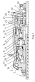
- Fig. 1 shows a half section through a power shift hub gear with a separate Pawl carrier.
- This shift hub has a mountain gear with a reduction, a direct gear with the same driver and hub sleeve speed and an overdrive with a corresponding translation.
- the hub axle 1 is attached to the bicycle frame on both sides.
- the hub sleeve 2 is supported by roller bearings on a fixed end shield 3 and the one that is also mounted Driver 4 from.
- a planetary gear is located between the driver 4 and the hub sleeve 2 consisting of an axially fixed sun gear 5, a planet carrier 6, planetary gears 7 and a ring gear 8.
- the different gears are switched on and off by a spring-coupled switching element 9 switched by the hollow hub axle 1.
- the one driven by a sprocket Driver 4 has two drive segments, one of which is the Take control part 10 rotatably and on the other hand the pawl carrier 11 via Take backlash and carry.
- On the latch bracket 11 are sprung on the circumference Drive pawls and brake pawls arranged, each of the control part 10 in the driving contour on the ring gear 8 can be controlled.
- On the inside diameter of the Pawl carrier 11 are spring-loaded transmission pawls 12 attached by the spring-loaded switching sleeve 13 into the driving contour on the coupling piece 14 is turned on or off.
- the spring-loaded coupling piece 14 is axially displaceable but always non-rotatably connected to the planet carrier 6 and transmits the force to the planet carrier in the controlled state.
- the planet gear carrier 6 has on the end shield side via a screw thread that a Axial displacement of the brake cone 17 allows, causing the brake jacket 18 in cooperation with another cone on the bearing plate 3 against the Brake cylinder 19 is pressed.
- the brake cone 17 has spring-loaded springs Pawls 20, which are always in the corresponding driving contour on the hub shell intervene or be overtaken by the driving contour.
- the switching element 9 is in the direction of the sun gear 5 postponed. This can only take place when the force applied to the switching element 9 Spring coupling is less than the biasing force on the switching sleeve 13.
- the Switching sleeve 13 moves the coupling piece 14 and the spacer sleeve 21 and thus the switching element 9 in the direction of the sun gear 5.
- the starting contour 15 on the coupling piece 14 moves under the ring gear pawls 16 and controls them from the driving contour on the hub sleeve 2.
- the power flow runs from the driver 4 via the drive pawls of the pawl carrier 11 to the ring gear 8, via the planet gears 7 to the planet gear carrier 6, from there to the brake cone 17 and finally via the pawls 20 to the hub sleeve 2. If there is none for the gearbox shifting Switching readiness is present, so the switching work is briefly in the switching sleeve spring 22 temporarily stored until a favorable switching situation arises again.
- the shift element 9 is in the direction of the driver 4 pushed, the spacer sleeve 21 shifts the switching sleeve 13 against the pending spring force.
- the spring-loaded coupling piece 14 follows the retreating Switch sleeve 13 and gives the ring gear pawls 16 the opportunity in to pivot the driving contour on the hub sleeve 2.
- the flow of power runs from the driver 4 via the drive pawls of the pawl carrier 11 to the ring gear 8 and About the ring gear pawls 16 to the hub sleeve 2, the pawls 20 of the corresponding driving contour on the hub sleeve 2 overhauled. Should for the Shift operation on the part of the transmission is not ready to shift, so the Switching work temporarily stored in the spring in front of the switching element until a favorable switching situation arises again.
- the shifting element 9 will continue in the direction Driver 4 pushed, the spacer sleeve 21 moves the switching sleeve 13th against the pending spring force.
- the transmission pawls driven by the overhang collar 23 12 are released and swing into the driving contour on Coupling piece 14 a.
- the power flow runs from the driver 4 via the transmission pawls 12 of the jack carrier 11 to the coupling piece 14, from there on Planet carrier 6 and the planet gears 7 to the ring gear 8, where it from the ring gear pawls 16 is introduced into the hub sleeve 2.
- Be in this switch position the pawls 20 from the corresponding driving contour on the hub sleeve 2 outdated. Should not be ready for shifting on the part of the transmission the switching work is briefly in the spring in front of the switching element temporarily stored until a favorable switching situation arises again.
- the preloaded switching sleeve spring 22 acts on the switching sleeve 13 and moves this and the coupling piece 14 and the spacer 21 and thus the switching element 9 in the direction Sun gear 5.
- the switching sleeve 13 moves with its collar 24 under the Transmission pawls 12 and causes precentering if the pawls are not exactly positioned the transmission pawls 12 before being driven by the control contour 25 and are kept in the modulated state by the overrun collar 23. Should for the Shifting into direct gear on the part of the transmission is not ready to shift the switching work is temporarily stored in the switching sleeve spring, until a favorable switching situation arises again.
- the coaster brake process always takes place via the mountain gear ratio and is initiated by a reverse movement on the driver.
- the twists Driver 4 opposite the jack carrier 11.
- corresponding recesses are provided on the jack carrier 11, the necessary backlash for the control of the drive or brake pawls by the control part 10.
- the control part 10 seated on the driver in a manner fixed against relative rotation is opposite the pawl carrier 11 rotated, the drive pawls and Brake pawls of corresponding control profiles in the control part 10, the pawls partially encloses, reversed at the same time.
- the brake pawls engage on both sides effective driving contour on the ring gear 8.
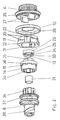
- Fig. 2 shows an exploded view with the essential, directly around the hub axis arranged gear components.
- the driver 4 takes on one side the gear on and has a raceway 26 for the rolling elements.
- the control part 10 is a molded plastic part and has control profiles 28 which are used for partly enclose the drive pawls and partly the brake pawls and with a relative movement of driver 4 and pawl carrier 11, the pawls each Turn on or off simultaneously according to the direction of rotation.
- the pawl carrier 11 is designed as a sintered molded part, without machining can be assembled.
- the circumference of the pawl receptacles 29 is opposite aligned drive and brake pawls provided. These handles are preloaded by a coil spring, which is an alternative to an all-round one Puncture of offset guide elements 30 is supported axially.
- At the Inner diameter of the pawl carrier 11 are in different circumferential sections on the one hand, recesses with the twist stops 31 for receiving the driving segments 27 and the other receiving troughs 32 for in the direction of the coupling piece 14 acting transmission pawls provided.
- the transmission jacks are sprung by a snap ring and axially fixed, as the snap ring attaches itself can support corresponding guide edges, not shown here.
- the shift sleeve 13 is a sintered molded part and is on the hub axle by means of a Longitudinal guide 33 rotatably guided.
- the start-up collar 24 takes over a possibly required one Pre-center the transmission pawls before moving from a cam Control contour 25 are controlled and then in this position by the thrust collar 23 are held.
- the switching sleeve 13 is in by the switching sleeve spring Biased towards the planet carrier 6 and via the spacer 21 from Shifting element axially shifted.
- the coupling piece 14 is also designed as a sintered molded part and is always over a coupling toothing 34 is connected to the planet gear carrier 6 in a rotationally fixed manner.
- the In the engaged state transmission pawls lie on the driving teeth 35 on.
- Analogous to the switching sleeve there is a start-up contour 15 on the control cam on the circumference 36 is provided, which with a corresponding displacement of the coupling piece 14 reaches under the ring gear pawls and controls them.
- the planet gear carrier rotates around the hub axis 6 and forms on one Side of the planetary gear guide 37, the counterpart to the clutch teeth 34.
- the other side is the seat of the brake cone 17 with the screw thread 38 for the axial displacement of the brake cone 17 during the backward movement the driver 4.
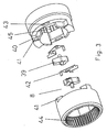
- Fig. 3 shows an exploded view of the ring gear 8 with the ring gear pawls, which as bolt-mounted sliding pawls 39 are formed.
- the ring gear is a sintered molded part designed and consists of two tool-falling halves, without cutting Post-processing is assembled without play after inserting the pawls become.
- the ring gear halves are matched to each other so that they are Support each other by means of radial guides 40 and twist stops 41.
- the Ring gear halves are not axially fixed to each other and are in the assembled state fixed by the planet carrier and the control section.
- the pawls 39 are of sheet springs 42, which are supported on the ring gear halves, biased and are stored with their bolt in opposite slots 43.
- the one Ring gear half has an internal toothing 44 which interacts with the planet gears, while in the other ring gear half the driving contour 45 for the drive or brake pawls are arranged.
- Fig. 4 shows the power flow in the various gear stages of the power shift hub gear.
- the power flow for the mountain gait is marked I and shown with a solid line.
- the switching element is in the left position, also marked with I. In this gear position, the driver speed is reduced, the hub sleeve consequently rotates more slowly than the driver driven by the pinion.
- the power flow in direct gear is marked II and is shown with a dash-dot line.
- the switching element is in the middle position, also marked II .
- the drive speed is passed on 1: 1 to the hub shell.
- the drive speed is translated into overdrive, the hub sleeve turns faster than the driver.
- the power flow is marked with III and is shown with a dashed line.
- the switching element is in the right position and is also marked III .
Landscapes
- Engineering & Computer Science (AREA)
- Chemical & Material Sciences (AREA)
- Combustion & Propulsion (AREA)
- Transportation (AREA)
- Mechanical Engineering (AREA)
- Structure Of Transmissions (AREA)
- Retarders (AREA)
Applications Claiming Priority (2)
| Application Number | Priority Date | Filing Date | Title |
|---|---|---|---|
| DE10134842A DE10134842A1 (de) | 2001-07-17 | 2001-07-17 | Lastschaltbare Mehrgangnabe |
| DE10134842 | 2001-07-17 |
Publications (3)
| Publication Number | Publication Date |
|---|---|
| EP1277649A2 true EP1277649A2 (fr) | 2003-01-22 |
| EP1277649A3 EP1277649A3 (fr) | 2005-02-23 |
| EP1277649B1 EP1277649B1 (fr) | 2008-06-25 |
Family
ID=7692152
Family Applications (1)
| Application Number | Title | Priority Date | Filing Date |
|---|---|---|---|
| EP02014742A Expired - Lifetime EP1277649B1 (fr) | 2001-07-17 | 2002-07-04 | Transmission pour moyeu à plusieurs vitesses |
Country Status (5)
| Country | Link |
|---|---|
| US (1) | US6692400B2 (fr) |
| EP (1) | EP1277649B1 (fr) |
| CN (1) | CN1325289C (fr) |
| DE (2) | DE10134842A1 (fr) |
| TW (1) | TW589269B (fr) |
Cited By (1)
| Publication number | Priority date | Publication date | Assignee | Title |
|---|---|---|---|---|
| EP3715676A4 (fr) * | 2017-11-23 | 2021-07-28 | Mbi Co. Ltd. | Dispositif d'aide à l'opération de changement de rapport de vitesses et transmission intégrée à un moyeu le comprenant |
Families Citing this family (20)
| Publication number | Priority date | Publication date | Assignee | Title |
|---|---|---|---|---|
| ATE303288T1 (de) † | 2003-02-28 | 2005-09-15 | Shimano Kk | Antriebsnabe für ein fahrrad |
| CN100521369C (zh) * | 2004-03-22 | 2009-07-29 | 通用汽车公司 | 用于混合式机电传动装置的接线连接模块 |
| DE102004014239A1 (de) * | 2004-03-24 | 2005-10-06 | Sram Deutschland Gmbh | Bremseinrichtung für eine Mehrgangnabe |
| DE102004034113A1 (de) * | 2004-07-15 | 2006-02-09 | Sram Deutschland Gmbh | Getriebenabe mit Bremseinrichtung |
| DE102005003056A1 (de) * | 2005-01-22 | 2006-07-27 | Sram Deutschland Gmbh | Schaltbewegungsübertragung in ein Fahrradgetriebe |
| EP1849699B1 (fr) * | 2006-04-28 | 2008-11-26 | Shimano Inc. | Moyeu de bicyclette à plusieurs vitesses avec frein à contre-pédalage |
| US7621842B2 (en) * | 2007-02-14 | 2009-11-24 | Shimano Inc. | Bicycle hub assembly |
| DE102007021970A1 (de) | 2007-05-10 | 2008-11-13 | Sram Deutschland Gmbh | Mehrgangnabe mit Friktionskupplung für begrenzbare Schaltlasten |
| US7874955B2 (en) * | 2007-09-28 | 2011-01-25 | Patterson Bicycle Transmission, Llc | Bicycle transmission system |
| US8100810B2 (en) * | 2007-12-28 | 2012-01-24 | Shimano Inc. | Bicycle internal hub transmission with helical gear |
| US8162340B2 (en) * | 2008-12-31 | 2012-04-24 | Sam Patterson | Spiral rotor chain shifting system |
| US8342553B2 (en) * | 2009-05-27 | 2013-01-01 | Patterson Bicycle Transmission Llc | Mounting method for bottom bracket planetary |
| DE102014208793A1 (de) | 2014-05-09 | 2015-11-12 | Zf Friedrichshafen Ag | Planetenradsatz |
| TWI606957B (zh) * | 2015-01-05 | 2017-12-01 | Internal transmission control mechanism | |
| US10041567B2 (en) * | 2015-03-20 | 2018-08-07 | Jen-chih Liu | Driving control system of internal clutch |
| US20190242459A1 (en) * | 2018-02-07 | 2019-08-08 | Jen-chih Liu | Control assembly of an internal clutch |
| TWI724652B (zh) * | 2019-11-27 | 2021-04-11 | 日馳企業股份有限公司 | 自行車變速裝置 |
| US20220221012A1 (en) * | 2020-08-03 | 2022-07-14 | Jen-chih Liu | Interior clutch-used control mechanism |
| US20220205494A1 (en) * | 2020-08-03 | 2022-06-30 | JEN-CHIH Lyang LIU | Interior clutch-used control mechanism |
| US20220213938A1 (en) * | 2020-08-03 | 2022-07-07 | Jen-chih Liu | Interior clutch-used control mechanism |
Citations (2)
| Publication number | Priority date | Publication date | Assignee | Title |
|---|---|---|---|---|
| DE2937126C2 (de) | 1978-09-13 | 1983-09-29 | Shimano Industrial Co., Ltd., Sakai, Osaka | Steuermechanismus für eine Fahrrad-Schaltnabe |
| DE3443592C2 (fr) | 1983-11-29 | 1989-08-10 | Shimano Industrial Co., Ltd., Sakai, Osaka, Jp |
Family Cites Families (19)
| Publication number | Priority date | Publication date | Assignee | Title |
|---|---|---|---|---|
| DE2209535C2 (de) * | 1972-02-29 | 1974-01-17 | Fichtel & Sachs Ag, 8720 Schweinfurt | Mehrgangübersetzungsnabe mit Rücktrittbremse |
| DE2232741C2 (de) * | 1972-07-04 | 1974-07-18 | Fichtel & Sachs Ag, 8720 Schweinfurt | Schaltzuglose Mehrgang-Nabe fm Fahrräder mit vereinfachter Achsfunktion |
| DE8228602U1 (de) * | 1982-10-12 | 1983-02-03 | Fichtel & Sachs Ag, 8720 Schweinfurt | Sperrklinkentraeger zu einem freilaufgesperre, insbesondere fahrraeder od. dgl. |
| DE3407164C2 (de) * | 1983-03-05 | 1993-11-18 | Fichtel & Sachs Ag | Mehrgang-Antriebsnabe für Fahrräder |
| DE3440068C2 (de) * | 1984-11-02 | 1993-12-02 | Fichtel & Sachs Ag | Mehrgang-Nabe für Fahrräder oder dergleichen |
| DE3440067A1 (de) * | 1984-11-02 | 1986-05-07 | Fichtel & Sachs Ag, 8720 Schweinfurt | Mehrgangnabe fuer fahrraeder oder dergleichen |
| GB8713238D0 (en) * | 1987-06-05 | 1987-07-08 | Sturmey Archer Ltd | Epicyclic change-speed gear mechanism |
| DE3732977A1 (de) * | 1987-09-30 | 1989-04-20 | Fichtel & Sachs Ag | Mehrgangnabe |
| DE3908989A1 (de) * | 1989-03-18 | 1990-09-20 | Sinterstahl Gmbh | Verfahren zur herstellung einer schalt- oder schiebemuffe fuer kfz-getriebe |
| DE4229023C2 (de) * | 1992-09-01 | 1995-02-16 | Fichtel & Sachs Ag | Schalteinrichtung für Mehrgangnabe |
| DE4313558A1 (de) * | 1993-04-26 | 1994-10-27 | Fichtel & Sachs Ag | Mehrgang-Fahrradnabe |
| DE4402344C1 (de) * | 1994-01-27 | 1995-03-16 | Fichtel & Sachs Ag | Steuereinrichtung für Klinkengesperre für Fahrrad-Mehrgangantriebsnaben |
| KR970042080A (ko) * | 1995-12-30 | 1997-07-24 | 마재열 | 자전거의 주행장치 |
| US6039671A (en) * | 1999-02-09 | 2000-03-21 | Kun Teng Industry Co., Ltd. | Multi-speed drive hub for a bicycle |
| EP1060980B1 (fr) * | 1999-06-17 | 2004-03-17 | SRAM Deutschland GmbH | Transmission de bicyclette à plusieurs vitesses |
| DE10014265C5 (de) * | 1999-06-17 | 2012-04-26 | Sram Deutschland Gmbh | Schalteinrichtung für eine Mehrgangnabe für ein Fahrrad |
| DE10061181A1 (de) * | 1999-12-24 | 2001-06-28 | Sram De Gmbh | Mehrgangnabe für ein Fahrrad |
| US6607465B1 (en) * | 2000-03-10 | 2003-08-19 | Shimano, Inc. | Bicycle hub transmission with a guiding member for a sun gear |
| US6558288B2 (en) * | 2001-05-18 | 2003-05-06 | Shimano, Inc. | Internal transmission device with automatic shift mechanism for a bicycle |
-
2001
- 2001-07-17 DE DE10134842A patent/DE10134842A1/de not_active Withdrawn
-
2002
- 2002-07-04 EP EP02014742A patent/EP1277649B1/fr not_active Expired - Lifetime
- 2002-07-04 DE DE50212400T patent/DE50212400D1/de not_active Expired - Lifetime
- 2002-07-10 TW TW091115306A patent/TW589269B/zh not_active IP Right Cessation
- 2002-07-16 CN CNB021407452A patent/CN1325289C/zh not_active Expired - Fee Related
- 2002-07-17 US US10/064,474 patent/US6692400B2/en not_active Expired - Fee Related
Patent Citations (2)
| Publication number | Priority date | Publication date | Assignee | Title |
|---|---|---|---|---|
| DE2937126C2 (de) | 1978-09-13 | 1983-09-29 | Shimano Industrial Co., Ltd., Sakai, Osaka | Steuermechanismus für eine Fahrrad-Schaltnabe |
| DE3443592C2 (fr) | 1983-11-29 | 1989-08-10 | Shimano Industrial Co., Ltd., Sakai, Osaka, Jp |
Cited By (1)
| Publication number | Priority date | Publication date | Assignee | Title |
|---|---|---|---|---|
| EP3715676A4 (fr) * | 2017-11-23 | 2021-07-28 | Mbi Co. Ltd. | Dispositif d'aide à l'opération de changement de rapport de vitesses et transmission intégrée à un moyeu le comprenant |
Also Published As
| Publication number | Publication date |
|---|---|
| DE50212400D1 (de) | 2008-08-07 |
| EP1277649B1 (fr) | 2008-06-25 |
| TW589269B (en) | 2004-06-01 |
| CN1397438A (zh) | 2003-02-19 |
| US6692400B2 (en) | 2004-02-17 |
| CN1325289C (zh) | 2007-07-11 |
| DE10134842A1 (de) | 2003-02-06 |
| EP1277649A3 (fr) | 2005-02-23 |
| US20030017905A1 (en) | 2003-01-23 |
Similar Documents
| Publication | Publication Date | Title |
|---|---|---|
| EP1277649A2 (fr) | Transmission pour moyeu à plusieurs vitesses | |
| DE102007004802B4 (de) | Mehrfachgetriebe für ein mit Muskelkraft angetriebenes Fahrzeug | |
| DE60119808T2 (de) | Fahrradantriebsnabe | |
| DE2940841C2 (fr) | ||
| EP0528383B1 (fr) | Moyeu d'entraînement pour un véhicule | |
| EP2617639B1 (fr) | Engrenage de vélo, en particulier sous forme d'un moyeu à vitesses multiples | |
| DE2819471C2 (de) | Freilaufnabe | |
| EP0910530B1 (fr) | Transmission a plusieurs vitesses pour bicyclettes | |
| EP2327617B1 (fr) | Engrenage à filetage multiple pour vélos | |
| EP0554874B1 (fr) | Moyeu d'entraînement à vitesses multiples pour bicyclette | |
| EP3759372B1 (fr) | Ensemble embrayage et transmission pour vehicule à moteur musculaire | |
| DE102008064514A1 (de) | Getriebeeinheit | |
| AT391668B (de) | Mehrgang-antriebsnabe mit wenigstens drei gaengen fuer fahrraeder | |
| EP3509935B1 (fr) | Système de propulsion et véhicule | |
| DE102016207035A1 (de) | Antriebsanordnung und Fahrzeug | |
| DE102010049438A1 (de) | Betätigungsmechanik für eine Mehrfach-Fahrradgetriebenabe | |
| EP0693419B1 (fr) | Transmission de bicyclette à plusieurs vitesses avec plus de trois vitesses | |
| EP3209544B1 (fr) | Transmission à anneau de friction disposé coaxialement pour un véhicule actionnable par une force motrice et/ou une force de pédales | |
| DD212702A5 (de) | Nabe fuer ein zweiradfahrzeug | |
| DE2232741C2 (de) | Schaltzuglose Mehrgang-Nabe fm Fahrräder mit vereinfachter Achsfunktion | |
| DE69702087T3 (de) | Antriebsnabe mit Bremse für ein Fahrrad | |
| EP2426043B1 (fr) | Engrenage de moyeu de bicyclette | |
| DE1092791B (de) | Mehrganguebersetzungsnabe fuer Fahr- und Motorraeder | |
| DE102022107408B3 (de) | Freilaufeinrichtung sowie Kupplungsanordnung mit der Freilaufeinrichtung | |
| EP4396475B1 (fr) | Unité d'engrenage pour un véhicule à deux roues |
Legal Events
| Date | Code | Title | Description |
|---|---|---|---|
| PUAI | Public reference made under article 153(3) epc to a published international application that has entered the european phase |
Free format text: ORIGINAL CODE: 0009012 |
|
| AK | Designated contracting states |
Kind code of ref document: A2 Designated state(s): AT BE BG CH CY CZ DE DK EE ES FI FR GB GR IE IT LI LU MC NL PT SE SK TR |
|
| AX | Request for extension of the european patent |
Free format text: AL;LT;LV;MK;RO;SI |
|
| PUAL | Search report despatched |
Free format text: ORIGINAL CODE: 0009013 |
|
| AK | Designated contracting states |
Kind code of ref document: A3 Designated state(s): AT BE BG CH CY CZ DE DK EE ES FI FR GB GR IE IT LI LU MC NL PT SE SK TR |
|
| AX | Request for extension of the european patent |
Extension state: AL LT LV MK RO SI |
|
| 17P | Request for examination filed |
Effective date: 20050317 |
|
| AKX | Designation fees paid |
Designated state(s): DE FR NL |
|
| 17Q | First examination report despatched |
Effective date: 20061205 |
|
| GRAP | Despatch of communication of intention to grant a patent |
Free format text: ORIGINAL CODE: EPIDOSNIGR1 |
|
| GRAS | Grant fee paid |
Free format text: ORIGINAL CODE: EPIDOSNIGR3 |
|
| GRAA | (expected) grant |
Free format text: ORIGINAL CODE: 0009210 |
|
| AK | Designated contracting states |
Kind code of ref document: B1 Designated state(s): DE FR NL |
|
| REF | Corresponds to: |
Ref document number: 50212400 Country of ref document: DE Date of ref document: 20080807 Kind code of ref document: P |
|
| PLBE | No opposition filed within time limit |
Free format text: ORIGINAL CODE: 0009261 |
|
| STAA | Information on the status of an ep patent application or granted ep patent |
Free format text: STATUS: NO OPPOSITION FILED WITHIN TIME LIMIT |
|
| 26N | No opposition filed |
Effective date: 20090326 |
|
| REG | Reference to a national code |
Ref country code: FR Ref legal event code: PLFP Year of fee payment: 14 |
|
| PGFP | Annual fee paid to national office [announced via postgrant information from national office to epo] |
Ref country code: FR Payment date: 20150626 Year of fee payment: 14 |
|
| PGFP | Annual fee paid to national office [announced via postgrant information from national office to epo] |
Ref country code: NL Payment date: 20150721 Year of fee payment: 14 |
|
| REG | Reference to a national code |
Ref country code: NL Ref legal event code: MM Effective date: 20160801 |
|
| PG25 | Lapsed in a contracting state [announced via postgrant information from national office to epo] |
Ref country code: FR Free format text: LAPSE BECAUSE OF NON-PAYMENT OF DUE FEES Effective date: 20160801 Ref country code: NL Free format text: LAPSE BECAUSE OF NON-PAYMENT OF DUE FEES Effective date: 20160801 |
|
| REG | Reference to a national code |
Ref country code: FR Ref legal event code: ST Effective date: 20170331 |
|
| PGFP | Annual fee paid to national office [announced via postgrant information from national office to epo] |
Ref country code: DE Payment date: 20170731 Year of fee payment: 16 |
|
| REG | Reference to a national code |
Ref country code: DE Ref legal event code: R119 Ref document number: 50212400 Country of ref document: DE |
|
| PG25 | Lapsed in a contracting state [announced via postgrant information from national office to epo] |
Ref country code: DE Free format text: LAPSE BECAUSE OF NON-PAYMENT OF DUE FEES Effective date: 20190201 |