EP1278013A2 - Pilotbrenner, Vormischungsverbrennungskammer und Gasturbine - Google Patents
Pilotbrenner, Vormischungsverbrennungskammer und Gasturbine Download PDFInfo
- Publication number
- EP1278013A2 EP1278013A2 EP02015648A EP02015648A EP1278013A2 EP 1278013 A2 EP1278013 A2 EP 1278013A2 EP 02015648 A EP02015648 A EP 02015648A EP 02015648 A EP02015648 A EP 02015648A EP 1278013 A2 EP1278013 A2 EP 1278013A2
- Authority
- EP
- European Patent Office
- Prior art keywords
- pilot
- tip
- fuel
- nozzle
- air guide
- Prior art date
- Legal status (The legal status is an assumption and is not a legal conclusion. Google has not performed a legal analysis and makes no representation as to the accuracy of the status listed.)
- Granted
Links
- 239000000446 fuel Substances 0.000 claims abstract description 61
- 239000007789 gas Substances 0.000 claims description 20
- 238000002347 injection Methods 0.000 claims description 12
- 239000007924 injection Substances 0.000 claims description 12
- 239000000567 combustion gas Substances 0.000 claims description 11
- 238000011144 upstream manufacturing Methods 0.000 claims description 6
- 239000000203 mixture Substances 0.000 claims description 5
- 230000002093 peripheral effect Effects 0.000 claims description 2
- 230000006698 induction Effects 0.000 description 31
- 230000000087 stabilizing effect Effects 0.000 description 21
- 230000004048 modification Effects 0.000 description 11
- 238000012986 modification Methods 0.000 description 11
- 238000002485 combustion reaction Methods 0.000 description 6
- 238000010276 construction Methods 0.000 description 1
- 238000010586 diagram Methods 0.000 description 1
- 230000001939 inductive effect Effects 0.000 description 1
- 231100000331 toxic Toxicity 0.000 description 1
- 230000002588 toxic effect Effects 0.000 description 1
Images


Classifications
-
- F—MECHANICAL ENGINEERING; LIGHTING; HEATING; WEAPONS; BLASTING
- F23—COMBUSTION APPARATUS; COMBUSTION PROCESSES
- F23R—GENERATING COMBUSTION PRODUCTS OF HIGH PRESSURE OR HIGH VELOCITY, e.g. GAS-TURBINE COMBUSTION CHAMBERS
- F23R3/00—Continuous combustion chambers using liquid or gaseous fuel
- F23R3/28—Continuous combustion chambers using liquid or gaseous fuel characterised by the fuel supply
- F23R3/34—Feeding into different combustion zones
- F23R3/343—Pilot flames, i.e. fuel nozzles or injectors using only a very small proportion of the total fuel to insure continuous combustion
-
- F—MECHANICAL ENGINEERING; LIGHTING; HEATING; WEAPONS; BLASTING
- F23—COMBUSTION APPARATUS; COMBUSTION PROCESSES
- F23R—GENERATING COMBUSTION PRODUCTS OF HIGH PRESSURE OR HIGH VELOCITY, e.g. GAS-TURBINE COMBUSTION CHAMBERS
- F23R3/00—Continuous combustion chambers using liquid or gaseous fuel
- F23R3/02—Continuous combustion chambers using liquid or gaseous fuel characterised by the air-flow or gas-flow configuration
- F23R3/04—Air inlet arrangements
- F23R3/10—Air inlet arrangements for primary air
- F23R3/12—Air inlet arrangements for primary air inducing a vortex
- F23R3/14—Air inlet arrangements for primary air inducing a vortex by using swirl vanes
-
- F—MECHANICAL ENGINEERING; LIGHTING; HEATING; WEAPONS; BLASTING
- F23—COMBUSTION APPARATUS; COMBUSTION PROCESSES
- F23R—GENERATING COMBUSTION PRODUCTS OF HIGH PRESSURE OR HIGH VELOCITY, e.g. GAS-TURBINE COMBUSTION CHAMBERS
- F23R3/00—Continuous combustion chambers using liquid or gaseous fuel
- F23R3/28—Continuous combustion chambers using liquid or gaseous fuel characterised by the fuel supply
- F23R3/286—Continuous combustion chambers using liquid or gaseous fuel characterised by the fuel supply having fuel-air premixing devices
Definitions
- the present invention relates to a pilot burner, a premixing combustor, and a gas turbine that generate a stable flame.
- Fig. 8 depicts a pilot burner and a main burner of a premixing combustor in a conventional gas turbine.
- a pilot burner 70 consists of an outer cylinder 71, a pilot swirler 72, a pilot nozzle 73 and a pilot cone 74. Fuel is injected and diffused in the premixing combustor, as shown by black arrows 75, from the pilot nozzle 73. A plurality of premixing nozzles 76 those inject premixed gas are provided around the pilot nozzle 73 . This fuel injected from the pilot nozzle 73 is burnt in the form of a flame and this flame helps combust the premixed gas injected from the premixing nozzles 76.
- Pilot air is made to flow from left ("upstream") to right ("downstream”) as shown by white arrows.
- the pilot swirler 72 functions to circulate the pilot air around the pilot nozzle 73 to improve the combustion efficiency.
- the pilot swirler 72 surrounds the pilot nozzle 73. However, the pilot swirler 72 is not directly attached to the pilot nozzle 73 but arranged towards the side of the outer cylinder 71.
- the combustion of the premixed gas is conducted at a high temperature of about 1500 degree centigrade to suppress generation of toxic thermal NOx gas.
- the combustion of the fuel is conducted at relatively low temperature.
- thermal NOx is disadvantageously generated during the combustion of the fuel.
- the amount of thermal Nox generated may be reduced by reducing the amount of the fuel. However, if the fuel reduced, the flame obtained by burning the fuel becomes unstable. In the worst case the flame may be extinguished because of the blow of the pilot air. Since this flame has a great influence on the combustion of the premixed gas, it is preferable that the flame is stable and does not extinguish.
- a pilot nozzle diffusion-injects a fuel
- a pilot swirler swirls a pilot air around the pilot nozzle
- an air guide is arranged between the outer surface of the pilot nozzle and the pilot swirler.
- the air guide extends from the pilot swirler to a tip of the pilot nozzle.
- the air guide has a tip that protrudes beyond the tip of the pilot nozzle and this the tip of the air guide is bent away from a center of the pilot nozzle.
- a pilot nozzle diffusion-injects a fuel
- a pilot swirler swirls a pilot air around the pilot nozzle
- an air guide is arranged between the outer surface of the pilot nozzle and the pilot swirler.
- the air guide extends from the pilot swirler to a tip of the pilot nozzle.
- the air guide has a tip that protrudes beyond the tip of the pilot nozzle and this the tip of the air guide is bent radially with respect to a center of the pilot nozzle.
- the premixing combustor according another aspect of the present invention is provided with the pilot burner according to the present invention.
- the gas turbine according still another aspect of the present invention is provided with the pilot burner according to the present invention.
- Fig. 1 depicts an overall view of the gas turbine 1 according to one embodiment of the present invention.
- the gas turbine 1 consists of a compressor 2, a combustor 3 and a turbine 4 among other structure. Air is introduced in the combustor 2 from an air inlet 5. The compressor 2 compresses the air with the help of a plurality of moving blades 6 and stationary blades 7. The compressed air is feed to the combustor 3. In the combustor 3, the compressed air is mixed with a fuel, the mixture of air and fuel is combust to obtain high pressure combustion gas. The combustion gas is made to pass through a tail pipe 8 and rotate the turbine.
- the turbine has a plurality of stages of rotors.
- Fig. 2 depicts a premixing combustor 10 according to one embodiment of the present invention.
- the premixing combustor 10 includes a pilot burner 11 and a plurality of premixing nozzles 12 arranged around the pilot burner 11.
- the pilot burner 11 and the premixing nozzles 12 enclosed by a cylindrical container 13.
- the premixing nozzles 12 are supported by a main swirler 14 and inject and mix a fuel to and with the compressed air which is turned into a revolving flow by the main swirler 14.
- the pilot burner 11 is supported by a pilot swirler 15 near its tip end and injects a pilot fuel diagonally forward from the tip end. As a result, a flame generated thereby becomes a starting flame which helps the premixing nozzles 12 combust the premixed gas.
- the pilot swirler 15 is provided with an air induction plate 16 to be almost closely attached to the side surface of the pilot nozzle 11 toward the direction of the tip end of the pilot nozzle 11.
- the end of the air induction plate which is located on the tip end of the pilot nozzle 11 is provided to be bent radially relative to the axis of the pilot nozzle 11.
- This air induction plate 16 entangles the compressed air which is carried from the upstream and forms a vortex. As a result, the fuel which is injected from the pilot nozzle 11 and the air stay, making it possible to generate a stable starting flame.
- FIG. 3 is an enlarged outside view which shows the pilot burner according to this embodiment.
- Apilot swirler 21 is provided on an outer cylinder 23 to surround a pilot nozzle 22.
- An air induction plate 24 is provided to be almost closely attached to the side surface of the pilot nozzle from the pilot swirler 21 toward the direction of the tip end of the pilot nozzle 22.
- the air induction plate 24 is almost closely attached to the side surface of the pilot nozzle 22 in view of processing error, assembly error, thermal expansion error. Ideally, this means that the air introduction plate 24 is closely attached to the side surface of the pilot nozzle 22.
- An injection port (not shown) is provided on the tip end of the pilot nozzle 22 and a fuel is spread and injected from the injection port diagonally forward as indicated by an arrow 25.
- the pilot swirler 21 functions to revolve the pilot air which flows in a space which is formed between the outer cylinder 23 and the pilot nozzle 22 from the upstream and to enhance combustion efficiency.
- the end 27 of the air induction plate 24 is located on the tip end of the pilot nozzle 22 and bent radially outward relative to the axis of the pilot nozzle 22.
- the pilot air 26 turns around at the bent portion as indicated by an arrow 28 and a vortex is generated. This vortex can suppress the fuel from being blown away and prevent the fuel from being diluted by the flow of the pilot air 26, so that flame stabilizing capability eventually enhances. If the flame stabilizing capability enhances, it is possible to operate the combustor with a reduced pilot fuel and to thereby contribute to the reduction of the thermal NOx which recently surfaces as an issue.
- Fig. 4 depicts a first modification of the pilot burner according to this embodiment.
- an angle to which the end 31 of the air induction plate is bent is adjusted to spread and injected fuel diagonally forward from the pilot nozzle 22 as indicated by an arrow 25 directly collides against the end 31.
- the pilot air 26 generates a vortex on the end 31 as indicated by an arrow 32 and the pilot air 26 is fully mixed with the fuel. Besides, at a collision point at which the fuel collides against the end 31, a fuel stagnation point appears. In this respect, similarly to the embodiment, it is possible to prevent the fuel from being diluted and to enhance flame stabilizing capability.
- Fig. 5 depicts a secondmodification of the pilot burner according to this embodiment.
- the end 42 of an air induction plate 41 is bent radially inward relative to the axis.
- the air and the fuel are first fully mixed with each other in a clearance 43 which is formed between the end 42 of the air induction plate 41 and a fuel injection port (not shown) .
- a vortex 44 which turns the mixture gas outward around the end 42 of the air induction plate 41 is generated. This can enhance the flame stabilizing capability of the pilot burner.
- Fig. 6 depicts a third modification of the pilot burner according to this embodiment.
- This pilot burner is characterized in that the pilot swirler 21 which is conventionally provided on an outer cylinder 23 side is provided on the side surface 50 of the pilot nozzle 22.
- a plurality of pilot swirlers 21 are provided uniformly in the peripheral direction of the pilot nozzle 22.
- the air induction plate 51 is not always required to be connected to the pilot swirlers 21. Further, to secure a function of inducing the pilot air 26 toward the tip end of the pilot nozzle 22, it is necessary to provide the air induction plate 51 to be almost closely attached to the pilot nozzle side surface 52 with a certain point on the side surface 52 from the pilot swirlers 21 toward the direction of the tip end of the pilot nozzle 22 set as a starting point. The reason for almost closely attaching the air induction plate 51 to the pilot nozzle side surface 52 is the same as that explained in the embodiment.
- the end 53 of the air induction plate 51 is bent radially outward relative to the axis of the pilot nozzle 22.
- the bent shape is not limited thereto but may be radially inward or a bent angle at which the fuel spread and injected collides against the end 53 as indicated by an arrow 54 may be selected.
- the flame stabilizing capability enhances by the mixture of the pilot air and the fuel in the vortex and the appearance of a stagnation point similarly to the embodiment and the first to second modifications.
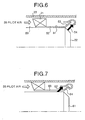
- Fig. 7 depicts a fourth modification of the pilot burner according to this embodiment.
- This pilot burner is characterized by the injection position of a fuel spread and injected from the injection port of a pilot nozzle 61. That is, as indicated by an arrow 62, the fuel injection port is provided upward of the bend 64 of an air induction plate 63. A hole is provided in the air induction plate 63 to be matched to the injection port position. By doing so, the fuel is mixed with the air before the air is entangled in the bent portion 64.
- the premixed gas of the air and the fuel is entangled in the bent portion 64 of the air induction plate 63, a vortex is generated and the fuel can be prevented from being diluted. Consequently, compared with a case in which only the air is entangled, the flame stabilizing capability enhances and it is possible to stably combust the gas with reduced fuel. A saving in fuel naturally contributes to the reduction of NOx.
- the air induction plate is similar to that in Fig. 3. However, the air induction plate is not limited thereto but may be any one of the air induction plates shown in Figs. 4 to 6.
- the end of the air induction plate is bent radially. In the bent portion, therefore, a vortex of the pilot air and a fuel stagnation point is generated. These phenomena can advantageously prevent the combustion gas from being diluted and enhance the flame stabilizing capability of the pilot burner. In addition, since the flame stabilizing capability enhances, it is possible to operate the. pilot burner with reduced fuel and to contribute to the thermal NOx reduction.
- the end of the air induction plate is bent radially outward. In the bent portion, therefore, a vortex of the pilot air and a fuel stagnation point is generated. These phenomena can advantageously prevent the combustion gas from being diluted and enhance the flame stabilizing capability of the pilot burner. In addition, since the flame stabilizing capability enhances, it is possible to operate the pilot burner with reduced fuel and to contribute to the thermal NOx reduction.
- the end of the air induction plate is bent radially outward and the fuel collides against the end. In the bent portion, therefore,' a vortex of the pilot air and a fuel stagnation point is generated. These phenomena can advantageously prevent the combustion gas from being diluted and enhance the flame stabilizing capability of the pilot burner. In addition, since the flame stabilizing capability enhances, it is possible to operate the pilot burner with reduced fuel and to contribute to the thermal NOx reduction.
- the end of the air induction plate is bent radially inward. In the bent portion, therefore, the fuel is well mixed with the pilot air and a vortex outward of the end is then generated. These phenomena can advantageously prevent the combustion gas from being diluted and enhance the flame stabilizing capability of the pilot burner. In addition, since the flame stabilizing capability enhances, it is possible to operate the pilot burner with reduced fuel and to contribute to the thermal NOx reduction.
- pilot swirlers and the air induction plate are provided on the side surface of the pilot nozzle and the end of the air induction plate is bent radially. In the bent portion, therefore, the fuel is well mixed with the pilot air and a vortex outward of the end is then generated. These phenomena can advantageously prevent the combustion gas from being diluted and enhance the flame stabilizing capability of the pilot burner. In addition, since the flame stabilizing capability enhances, it is possible to operate the pilot burner with reduced fuel and to contribute to the thermal NOx reduction.
- the injection port is provided upward of the bent portion of the end of the air induction plate and the fuel is injected diagonally forward from the hole provided in the side surface of the air induction plate. Therefore, while the air which flows from the upstream is premixed with the fuel, the premixed gas is entangled in the bent portion. If the air thus mixed with the fuel generates a vortex on the tip end of the pilot nozzle, the combustion gas is prevented from being diluted and the flame stabilizing capability of the pilot burner is enhanced. In addition, since the flame stabilizing capability enhances, it is possible to operate the pilot burner with reduced fuel and to contribute to the thermal NOx reduction.
- the premixing combustor of the present invention utilizes the pilot burner of a premixing combustor according to present invention. Therefore, the air mixed with the fuel generates a vortex on the tip end of the pilot nozzle and the combustion gas can be thereby prevented from being diluted. As a result, the flame stabilizing capability of the pilot burner can be enhanced. In addition, since the flame stabilizing capability enhances, it is possible to operate the pilot burner with reduced fuel and to realize a premixing combustor which can reduce the thermal NOx.
- the gas turbine of the present invention utilizes the premixing combustor according to present invention. It is, therefore, possible to enhance the flame stabilizing capability of the pilot burner and to provide a gas turbine which can reduce the thermal NOx by the reduction of the fuel.
Landscapes
- Engineering & Computer Science (AREA)
- Chemical & Material Sciences (AREA)
- Combustion & Propulsion (AREA)
- Mechanical Engineering (AREA)
- General Engineering & Computer Science (AREA)
- Gas Burners (AREA)
- Combustion Of Fluid Fuel (AREA)
Applications Claiming Priority (2)
| Application Number | Priority Date | Filing Date | Title |
|---|---|---|---|
| JP2001217233 | 2001-07-17 | ||
| JP2001217233A JP2003028425A (ja) | 2001-07-17 | 2001-07-17 | 予混合燃焼器のパイロットバーナー、予混合燃焼器、およびガスタービン |
Publications (3)
| Publication Number | Publication Date |
|---|---|
| EP1278013A2 true EP1278013A2 (de) | 2003-01-22 |
| EP1278013A3 EP1278013A3 (de) | 2004-04-14 |
| EP1278013B1 EP1278013B1 (de) | 2012-12-19 |
Family
ID=19051603
Family Applications (1)
| Application Number | Title | Priority Date | Filing Date |
|---|---|---|---|
| EP02015648A Expired - Lifetime EP1278013B1 (de) | 2001-07-17 | 2002-07-16 | Pilotbrenner, Vormischungsverbrennungskammer und Gasturbine |
Country Status (5)
| Country | Link |
|---|---|
| US (1) | US6701713B2 (de) |
| EP (1) | EP1278013B1 (de) |
| JP (1) | JP2003028425A (de) |
| CN (1) | CN1397761A (de) |
| CA (1) | CA2393863C (de) |
Cited By (7)
| Publication number | Priority date | Publication date | Assignee | Title |
|---|---|---|---|---|
| EP1279897A2 (de) | 2001-07-24 | 2003-01-29 | Mitsubishi Heavy Industries, Ltd. | Pilotdüse für Gasturbinenverbrennungskammer |
| CN102200291A (zh) * | 2011-03-29 | 2011-09-28 | 北京航空航天大学 | 一种采用气动主级分级的低污染燃烧室 |
| CN102242940A (zh) * | 2011-07-29 | 2011-11-16 | 北京航空航天大学 | 一种结构分三级预混预蒸发的低污染燃烧室 |
| CN102242939A (zh) * | 2011-07-29 | 2011-11-16 | 北京航空航天大学 | 一种预膜式分三级预混预蒸发的低污染燃烧室 |
| CN102901127A (zh) * | 2012-09-11 | 2013-01-30 | 北京航空航天大学 | 一种主燃级双层预膜三旋流的预混预蒸发低污染燃烧室 |
| ITMI20111943A1 (it) * | 2011-10-26 | 2013-04-27 | Ansaldo Energia Spa | Metodo per modificare un gruppo bruciatore di una turbina a gas |
| EP2249003A4 (de) * | 2008-02-27 | 2015-03-18 | Mitsubishi Heavy Ind Ltd | Gasturbine und verfahren zum öffnen des gehäuses einer gasturbine |
Families Citing this family (26)
| Publication number | Priority date | Publication date | Assignee | Title |
|---|---|---|---|---|
| JP3986348B2 (ja) * | 2001-06-29 | 2007-10-03 | 三菱重工業株式会社 | ガスタービン燃焼器の燃料供給ノズルおよびガスタービン燃焼器並びにガスタービン |
| JP3944609B2 (ja) * | 2003-12-16 | 2007-07-11 | 川崎重工業株式会社 | 燃料ノズル |
| KR100436601B1 (ko) * | 2003-12-20 | 2004-06-18 | 학교법인 영남학원 | 저 질소산화물 배출 및 고부하 연소용 예혼합 연료분출장치 |
| US7093444B2 (en) * | 2003-12-20 | 2006-08-22 | Yeungnam Educational Foundation | Simultaneous combustion with premixed and non-premixed fuels and fuel injector for such combustion |
| US7752850B2 (en) * | 2005-07-01 | 2010-07-13 | Siemens Energy, Inc. | Controlled pilot oxidizer for a gas turbine combustor |
| EP1936276A1 (de) * | 2006-12-22 | 2008-06-25 | Siemens Aktiengesellschaft | Brenner für eine Gasturbine |
| US20100175380A1 (en) * | 2009-01-13 | 2010-07-15 | General Electric Company | Traversing fuel nozzles in cap-less combustor assembly |
| US20100326079A1 (en) * | 2009-06-25 | 2010-12-30 | Baifang Zuo | Method and system to reduce vane swirl angle in a gas turbine engine |
| US9017064B2 (en) | 2010-06-08 | 2015-04-28 | Siemens Energy, Inc. | Utilizing a diluent to lower combustion instabilities in a gas turbine engine |
| JP5821545B2 (ja) * | 2011-11-08 | 2015-11-24 | 株式会社Ihi | バーナ及び燃焼器 |
| US8701419B2 (en) * | 2012-05-10 | 2014-04-22 | General Electric Company | Multi-tube fuel nozzle with mixing features |
| US9222673B2 (en) * | 2012-10-09 | 2015-12-29 | General Electric Company | Fuel nozzle and method of assembling the same |
| JP6430756B2 (ja) | 2014-09-19 | 2018-11-28 | 三菱日立パワーシステムズ株式会社 | 燃焼バーナ及び燃焼器、並びにガスタービン |
| JP5913503B2 (ja) | 2014-09-19 | 2016-04-27 | 三菱重工業株式会社 | 燃焼バーナ及び燃焼器、並びにガスタービン |
| JP6521283B2 (ja) | 2014-09-25 | 2019-05-29 | 三菱日立パワーシステムズ株式会社 | 燃焼器、ガスタービン |
| CN104390235B (zh) * | 2014-11-20 | 2017-06-27 | 中国船舶重工集团公司第七�三研究所 | 预混旋流式值班喷嘴 |
| CN104654358B (zh) * | 2015-02-13 | 2017-09-15 | 北京华清燃气轮机与煤气化联合循环工程技术有限公司 | 一种带有引流结构的燃烧室预混合燃料喷嘴 |
| CN105650679A (zh) * | 2016-01-19 | 2016-06-08 | 西北工业大学 | 一种三级旋流部分预混的地面燃机燃烧室 |
| JP6768306B2 (ja) * | 2016-02-29 | 2020-10-14 | 三菱パワー株式会社 | 燃焼器、ガスタービン |
| JP6934359B2 (ja) * | 2017-08-21 | 2021-09-15 | 三菱パワー株式会社 | 燃焼器及びその燃焼器を備えるガスタービン |
| KR102046455B1 (ko) * | 2017-10-30 | 2019-11-19 | 두산중공업 주식회사 | 연료 노즐, 이를 포함하는 연소기 및 가스 터빈 |
| JP7193962B2 (ja) * | 2018-09-26 | 2022-12-21 | 三菱重工業株式会社 | 燃焼器及びこれを備えたガスタービン |
| CN113137634B (zh) * | 2021-06-02 | 2022-04-26 | 厦门大学 | 一种变结构双模态冲压燃烧室 |
| CN113983494B (zh) * | 2021-09-22 | 2022-10-21 | 南京航空航天大学 | 一种扩压比智能可调的燃气轮机主燃烧室多通道扩压器 |
| CN114857621B (zh) * | 2022-05-07 | 2023-05-12 | 燕山大学 | 用于高压非牛顿流体的雾化射流喷嘴装置及雾化方法 |
| CN115682034B (zh) * | 2022-10-27 | 2024-12-10 | 西北工业大学 | 一种吸气式脉冲爆震燃烧室及其起爆方法 |
Family Cites Families (8)
| Publication number | Priority date | Publication date | Assignee | Title |
|---|---|---|---|---|
| JP3197103B2 (ja) * | 1993-03-08 | 2001-08-13 | 三菱重工業株式会社 | 予混合気の燃焼方法 |
| US5359847B1 (en) * | 1993-06-01 | 1996-04-09 | Westinghouse Electric Corp | Dual fuel ultra-flow nox combustor |
| US5394688A (en) * | 1993-10-27 | 1995-03-07 | Westinghouse Electric Corporation | Gas turbine combustor swirl vane arrangement |
| JP2858104B2 (ja) * | 1996-02-05 | 1999-02-17 | 三菱重工業株式会社 | ガスタービン燃焼器 |
| WO1998040670A1 (en) * | 1997-03-13 | 1998-09-17 | Westinghouse Electric Corporation | AN IMPROVED COMBUSTOR FOR LOW CO, LOW NOx FORMATION |
| JP2001254947A (ja) | 2000-03-14 | 2001-09-21 | Mitsubishi Heavy Ind Ltd | ガスタービン燃焼器 |
| JP2002039533A (ja) * | 2000-07-21 | 2002-02-06 | Mitsubishi Heavy Ind Ltd | 燃焼器、ガスタービン及びジェットエンジン |
| JP4508474B2 (ja) * | 2001-06-07 | 2010-07-21 | 三菱重工業株式会社 | 燃焼器 |
-
2001
- 2001-07-17 JP JP2001217233A patent/JP2003028425A/ja active Pending
-
2002
- 2002-07-16 US US10/195,412 patent/US6701713B2/en not_active Expired - Lifetime
- 2002-07-16 CA CA002393863A patent/CA2393863C/en not_active Expired - Lifetime
- 2002-07-16 EP EP02015648A patent/EP1278013B1/de not_active Expired - Lifetime
- 2002-07-17 CN CN02126339A patent/CN1397761A/zh active Pending
Cited By (14)
| Publication number | Priority date | Publication date | Assignee | Title |
|---|---|---|---|---|
| EP1279897A2 (de) | 2001-07-24 | 2003-01-29 | Mitsubishi Heavy Industries, Ltd. | Pilotdüse für Gasturbinenverbrennungskammer |
| EP1279897B1 (de) * | 2001-07-24 | 2014-01-01 | Mitsubishi Heavy Industries, Ltd. | Pilotdüse für Gasturbinenverbrennungskammer |
| US9080464B2 (en) | 2008-02-27 | 2015-07-14 | Mitsubishi Hitachi Power Systems, Ltd. | Gas turbine and method of opening chamber of gas turbine |
| EP2249003A4 (de) * | 2008-02-27 | 2015-03-18 | Mitsubishi Heavy Ind Ltd | Gasturbine und verfahren zum öffnen des gehäuses einer gasturbine |
| CN102200291B (zh) * | 2011-03-29 | 2013-12-11 | 北京航空航天大学 | 一种采用气动主级分级的低污染燃烧室 |
| CN102200291A (zh) * | 2011-03-29 | 2011-09-28 | 北京航空航天大学 | 一种采用气动主级分级的低污染燃烧室 |
| CN102242939A (zh) * | 2011-07-29 | 2011-11-16 | 北京航空航天大学 | 一种预膜式分三级预混预蒸发的低污染燃烧室 |
| CN102242939B (zh) * | 2011-07-29 | 2013-12-11 | 北京航空航天大学 | 一种预膜式分三级预混预蒸发的低污染燃烧室 |
| CN102242940B (zh) * | 2011-07-29 | 2014-02-12 | 北京航空航天大学 | 一种结构分三级预混预蒸发的低污染燃烧室 |
| CN102242940A (zh) * | 2011-07-29 | 2011-11-16 | 北京航空航天大学 | 一种结构分三级预混预蒸发的低污染燃烧室 |
| WO2013061303A1 (en) * | 2011-10-26 | 2013-05-02 | Ansaldo Energia S.P.A. | Method for modifying a gas turbine burner assembly |
| ITMI20111943A1 (it) * | 2011-10-26 | 2013-04-27 | Ansaldo Energia Spa | Metodo per modificare un gruppo bruciatore di una turbina a gas |
| CN102901127B (zh) * | 2012-09-11 | 2014-10-15 | 北京航空航天大学 | 一种主燃级双层预膜三旋流的预混预蒸发低污染燃烧室 |
| CN102901127A (zh) * | 2012-09-11 | 2013-01-30 | 北京航空航天大学 | 一种主燃级双层预膜三旋流的预混预蒸发低污染燃烧室 |
Also Published As
| Publication number | Publication date |
|---|---|
| CN1397761A (zh) | 2003-02-19 |
| US20030014976A1 (en) | 2003-01-23 |
| CA2393863C (en) | 2007-07-10 |
| US6701713B2 (en) | 2004-03-09 |
| JP2003028425A (ja) | 2003-01-29 |
| EP1278013B1 (de) | 2012-12-19 |
| EP1278013A3 (de) | 2004-04-14 |
| CA2393863A1 (en) | 2003-01-17 |
Similar Documents
| Publication | Publication Date | Title |
|---|---|---|
| US6701713B2 (en) | Pilot burner, premixing combustor, and gas turbine | |
| KR0149059B1 (ko) | 가스터빈연소기 | |
| US7673455B2 (en) | Gas turbine combustor and fuel supply method for same | |
| EP1985927B1 (de) | Verbrennungssystem einer Gasturbine mit Mager-Direkt-Einspritzung zur Reduzierung von NOx-Emissionen | |
| US6374615B1 (en) | Low cost, low emissions natural gas combustor | |
| KR101470774B1 (ko) | 노즐 및 가스 터빈 연소기, 가스 터빈 | |
| US6631614B2 (en) | Gas turbine combustor | |
| US8117845B2 (en) | Systems to facilitate reducing flashback/flame holding in combustion systems | |
| EP2551598B1 (de) | Verfahren zum betreiben einer turbomaschine | |
| JPH07305846A (ja) | ガスタービン用燃焼装置 | |
| JP2003262336A (ja) | ガスタービン燃焼器 | |
| JP4086767B2 (ja) | 燃焼器のエミッションを低減する方法及び装置 | |
| JP2000130757A (ja) | ガス化発電プラントのガスタービン燃焼器 | |
| JP3959632B2 (ja) | 拡散燃焼方式低NOx燃焼器 | |
| JPS597885B2 (ja) | ガスバ−ナノズル | |
| JP2004170010A (ja) | ガスタービン燃焼器及びガスタービン燃焼器の燃料供給方法 | |
| JP5574635B2 (ja) | 旋回翼 | |
| CN118829827A (zh) | 燃气涡轮机燃烧器及燃气涡轮机 | |
| JPH0942672A (ja) | ガスタービン燃焼器 | |
| JP3272447B2 (ja) | ガス燃料用バーナ | |
| JP6182395B2 (ja) | ガスタービン燃焼器及びその制御方法 | |
| JP2025101202A (ja) | ガスバーナ | |
| CN102959334A (zh) | 燃烧设备 | |
| JPH07260149A (ja) | ガスタービン燃焼器 | |
| JP2002061841A (ja) | 燃焼器、ガスタービンおよびジェットエンジン |
Legal Events
| Date | Code | Title | Description |
|---|---|---|---|
| PUAI | Public reference made under article 153(3) epc to a published international application that has entered the european phase |
Free format text: ORIGINAL CODE: 0009012 |
|
| 17P | Request for examination filed |
Effective date: 20020716 |
|
| AK | Designated contracting states |
Kind code of ref document: A2 Designated state(s): AT BE BG CH CY CZ DE DK EE ES FI FR GB GR IE IT LI LU MC NL PT SE SK TR |
|
| AX | Request for extension of the european patent |
Free format text: AL;LT;LV;MK;RO;SI |
|
| PUAL | Search report despatched |
Free format text: ORIGINAL CODE: 0009013 |
|
| AK | Designated contracting states |
Kind code of ref document: A3 Designated state(s): AT BE BG CH CY CZ DE DK EE ES FI FR GB GR IE IT LI LU MC NL PT SE SK TR |
|
| AX | Request for extension of the european patent |
Extension state: AL LT LV MK RO SI |
|
| RIC1 | Information provided on ipc code assigned before grant |
Ipc: 7F 23D 14/74 B Ipc: 7F 23R 3/20 A Ipc: 7F 23R 3/34 B |
|
| AKX | Designation fees paid |
Designated state(s): CH DE FR GB IT LI |
|
| 17Q | First examination report despatched |
Effective date: 20070828 |
|
| REG | Reference to a national code |
Ref country code: DE Ref legal event code: R079 Ref document number: 60244237 Country of ref document: DE Free format text: PREVIOUS MAIN CLASS: F23R0003200000 Ipc: F23R0003140000 |
|
| RIC1 | Information provided on ipc code assigned before grant |
Ipc: F23R 3/14 20060101AFI20120521BHEP Ipc: F23R 3/34 20060101ALI20120521BHEP Ipc: F23R 3/28 20060101ALI20120521BHEP |
|
| GRAP | Despatch of communication of intention to grant a patent |
Free format text: ORIGINAL CODE: EPIDOSNIGR1 |
|
| GRAS | Grant fee paid |
Free format text: ORIGINAL CODE: EPIDOSNIGR3 |
|
| GRAA | (expected) grant |
Free format text: ORIGINAL CODE: 0009210 |
|
| AK | Designated contracting states |
Kind code of ref document: B1 Designated state(s): CH DE FR GB IT LI |
|
| REG | Reference to a national code |
Ref country code: GB Ref legal event code: FG4D |
|
| REG | Reference to a national code |
Ref country code: CH Ref legal event code: EP |
|
| REG | Reference to a national code |
Ref country code: DE Ref legal event code: R096 Ref document number: 60244237 Country of ref document: DE Effective date: 20130214 |
|
| PLBI | Opposition filed |
Free format text: ORIGINAL CODE: 0009260 |
|
| PLAX | Notice of opposition and request to file observation + time limit sent |
Free format text: ORIGINAL CODE: EPIDOSNOBS2 |
|
| 26 | Opposition filed |
Opponent name: SIEMENS AKTIENGESELLSCHAFT Effective date: 20130919 |
|
| PG25 | Lapsed in a contracting state [announced via postgrant information from national office to epo] |
Ref country code: IT Free format text: LAPSE BECAUSE OF FAILURE TO SUBMIT A TRANSLATION OF THE DESCRIPTION OR TO PAY THE FEE WITHIN THE PRESCRIBED TIME-LIMIT Effective date: 20121219 |
|
| REG | Reference to a national code |
Ref country code: DE Ref legal event code: R026 Ref document number: 60244237 Country of ref document: DE Effective date: 20130919 |
|
| REG | Reference to a national code |
Ref country code: CH Ref legal event code: PL |
|
| PLAF | Information modified related to communication of a notice of opposition and request to file observations + time limit |
Free format text: ORIGINAL CODE: EPIDOSCOBS2 |
|
| GBPC | Gb: european patent ceased through non-payment of renewal fee |
Effective date: 20130716 |
|
| REG | Reference to a national code |
Ref country code: FR Ref legal event code: ST Effective date: 20140331 |
|
| PG25 | Lapsed in a contracting state [announced via postgrant information from national office to epo] |
Ref country code: GB Free format text: LAPSE BECAUSE OF NON-PAYMENT OF DUE FEES Effective date: 20130716 Ref country code: CH Free format text: LAPSE BECAUSE OF NON-PAYMENT OF DUE FEES Effective date: 20130731 Ref country code: LI Free format text: LAPSE BECAUSE OF NON-PAYMENT OF DUE FEES Effective date: 20130731 |
|
| PLBB | Reply of patent proprietor to notice(s) of opposition received |
Free format text: ORIGINAL CODE: EPIDOSNOBS3 |
|
| PG25 | Lapsed in a contracting state [announced via postgrant information from national office to epo] |
Ref country code: FR Free format text: LAPSE BECAUSE OF NON-PAYMENT OF DUE FEES Effective date: 20130731 |
|
| PLCK | Communication despatched that opposition was rejected |
Free format text: ORIGINAL CODE: EPIDOSNREJ1 |
|
| REG | Reference to a national code |
Ref country code: DE Ref legal event code: R100 Ref document number: 60244237 Country of ref document: DE |
|
| PLBN | Opposition rejected |
Free format text: ORIGINAL CODE: 0009273 |
|
| STAA | Information on the status of an ep patent application or granted ep patent |
Free format text: STATUS: OPPOSITION REJECTED |
|
| 27O | Opposition rejected |
Effective date: 20170320 |
|
| PGFP | Annual fee paid to national office [announced via postgrant information from national office to epo] |
Ref country code: DE Payment date: 20210622 Year of fee payment: 20 |
|
| REG | Reference to a national code |
Ref country code: DE Ref legal event code: R071 Ref document number: 60244237 Country of ref document: DE |