EP1278068A2 - Procédé et circuit de détection des déplacements utilisant des capteurs microélectromécaniques avec compensation de capacitances parasites - Google Patents
Procédé et circuit de détection des déplacements utilisant des capteurs microélectromécaniques avec compensation de capacitances parasites Download PDFInfo
- Publication number
- EP1278068A2 EP1278068A2 EP02015859A EP02015859A EP1278068A2 EP 1278068 A2 EP1278068 A2 EP 1278068A2 EP 02015859 A EP02015859 A EP 02015859A EP 02015859 A EP02015859 A EP 02015859A EP 1278068 A2 EP1278068 A2 EP 1278068A2
- Authority
- EP
- European Patent Office
- Prior art keywords
- sensing
- input terminal
- output
- sensor
- driving
- Prior art date
- Legal status (The legal status is an assumption and is not a legal conclusion. Google has not performed a legal analysis and makes no representation as to the accuracy of the status listed.)
- Granted
Links
Images


Classifications
-
- G—PHYSICS
- G01—MEASURING; TESTING
- G01D—MEASURING NOT SPECIALLY ADAPTED FOR A SPECIFIC VARIABLE; ARRANGEMENTS FOR MEASURING TWO OR MORE VARIABLES NOT COVERED IN A SINGLE OTHER SUBCLASS; TARIFF METERING APPARATUS; MEASURING OR TESTING NOT OTHERWISE PROVIDED FOR
- G01D5/00—Mechanical means for transferring the output of a sensing member; Means for converting the output of a sensing member to another variable where the form or nature of the sensing member does not constrain the means for converting; Transducers not specially adapted for a specific variable
- G01D5/12—Mechanical means for transferring the output of a sensing member; Means for converting the output of a sensing member to another variable where the form or nature of the sensing member does not constrain the means for converting; Transducers not specially adapted for a specific variable using electric or magnetic means
- G01D5/14—Mechanical means for transferring the output of a sensing member; Means for converting the output of a sensing member to another variable where the form or nature of the sensing member does not constrain the means for converting; Transducers not specially adapted for a specific variable using electric or magnetic means influencing the magnitude of a current or voltage
- G01D5/24—Mechanical means for transferring the output of a sensing member; Means for converting the output of a sensing member to another variable where the form or nature of the sensing member does not constrain the means for converting; Transducers not specially adapted for a specific variable using electric or magnetic means influencing the magnitude of a current or voltage by varying capacitance
- G01D5/241—Mechanical means for transferring the output of a sensing member; Means for converting the output of a sensing member to another variable where the form or nature of the sensing member does not constrain the means for converting; Transducers not specially adapted for a specific variable using electric or magnetic means influencing the magnitude of a current or voltage by varying capacitance by relative movement of capacitor electrodes
- G01D5/2417—Mechanical means for transferring the output of a sensing member; Means for converting the output of a sensing member to another variable where the form or nature of the sensing member does not constrain the means for converting; Transducers not specially adapted for a specific variable using electric or magnetic means influencing the magnitude of a current or voltage by varying capacitance by relative movement of capacitor electrodes by varying separation
-
- G—PHYSICS
- G01—MEASURING; TESTING
- G01D—MEASURING NOT SPECIALLY ADAPTED FOR A SPECIFIC VARIABLE; ARRANGEMENTS FOR MEASURING TWO OR MORE VARIABLES NOT COVERED IN A SINGLE OTHER SUBCLASS; TARIFF METERING APPARATUS; MEASURING OR TESTING NOT OTHERWISE PROVIDED FOR
- G01D3/00—Indicating or recording apparatus with provision for the special purposes referred to in the subgroups
- G01D3/06—Indicating or recording apparatus with provision for the special purposes referred to in the subgroups with provision for operation by a null method
- G01D3/066—Balancing a force which represents the measuring value, by means of a reference force
-
- G—PHYSICS
- G01—MEASURING; TESTING
- G01D—MEASURING NOT SPECIALLY ADAPTED FOR A SPECIFIC VARIABLE; ARRANGEMENTS FOR MEASURING TWO OR MORE VARIABLES NOT COVERED IN A SINGLE OTHER SUBCLASS; TARIFF METERING APPARATUS; MEASURING OR TESTING NOT OTHERWISE PROVIDED FOR
- G01D5/00—Mechanical means for transferring the output of a sensing member; Means for converting the output of a sensing member to another variable where the form or nature of the sensing member does not constrain the means for converting; Transducers not specially adapted for a specific variable
- G01D5/12—Mechanical means for transferring the output of a sensing member; Means for converting the output of a sensing member to another variable where the form or nature of the sensing member does not constrain the means for converting; Transducers not specially adapted for a specific variable using electric or magnetic means
- G01D5/14—Mechanical means for transferring the output of a sensing member; Means for converting the output of a sensing member to another variable where the form or nature of the sensing member does not constrain the means for converting; Transducers not specially adapted for a specific variable using electric or magnetic means influencing the magnitude of a current or voltage
- G01D5/24—Mechanical means for transferring the output of a sensing member; Means for converting the output of a sensing member to another variable where the form or nature of the sensing member does not constrain the means for converting; Transducers not specially adapted for a specific variable using electric or magnetic means influencing the magnitude of a current or voltage by varying capacitance
-
- G—PHYSICS
- G01—MEASURING; TESTING
- G01P—MEASURING LINEAR OR ANGULAR SPEED, ACCELERATION, DECELERATION, OR SHOCK; INDICATING PRESENCE, ABSENCE, OR DIRECTION, OF MOVEMENT
- G01P15/00—Measuring acceleration; Measuring deceleration; Measuring shock, i.e. sudden change of acceleration
- G01P15/02—Measuring acceleration; Measuring deceleration; Measuring shock, i.e. sudden change of acceleration by making use of inertia forces using solid seismic masses
- G01P15/08—Measuring acceleration; Measuring deceleration; Measuring shock, i.e. sudden change of acceleration by making use of inertia forces using solid seismic masses with conversion into electric or magnetic values
- G01P15/125—Measuring acceleration; Measuring deceleration; Measuring shock, i.e. sudden change of acceleration by making use of inertia forces using solid seismic masses with conversion into electric or magnetic values by capacitive pick-up
-
- G—PHYSICS
- G01—MEASURING; TESTING
- G01P—MEASURING LINEAR OR ANGULAR SPEED, ACCELERATION, DECELERATION, OR SHOCK; INDICATING PRESENCE, ABSENCE, OR DIRECTION, OF MOVEMENT
- G01P15/00—Measuring acceleration; Measuring deceleration; Measuring shock, i.e. sudden change of acceleration
- G01P15/02—Measuring acceleration; Measuring deceleration; Measuring shock, i.e. sudden change of acceleration by making use of inertia forces using solid seismic masses
- G01P15/08—Measuring acceleration; Measuring deceleration; Measuring shock, i.e. sudden change of acceleration by making use of inertia forces using solid seismic masses with conversion into electric or magnetic values
- G01P15/13—Measuring acceleration; Measuring deceleration; Measuring shock, i.e. sudden change of acceleration by making use of inertia forces using solid seismic masses with conversion into electric or magnetic values by measuring the force required to restore a proofmass subjected to inertial forces to a null position
- G01P15/131—Measuring acceleration; Measuring deceleration; Measuring shock, i.e. sudden change of acceleration by making use of inertia forces using solid seismic masses with conversion into electric or magnetic values by measuring the force required to restore a proofmass subjected to inertial forces to a null position with electrostatic counterbalancing means
-
- G—PHYSICS
- G01—MEASURING; TESTING
- G01P—MEASURING LINEAR OR ANGULAR SPEED, ACCELERATION, DECELERATION, OR SHOCK; INDICATING PRESENCE, ABSENCE, OR DIRECTION, OF MOVEMENT
- G01P15/00—Measuring acceleration; Measuring deceleration; Measuring shock, i.e. sudden change of acceleration
- G01P15/02—Measuring acceleration; Measuring deceleration; Measuring shock, i.e. sudden change of acceleration by making use of inertia forces using solid seismic masses
- G01P15/08—Measuring acceleration; Measuring deceleration; Measuring shock, i.e. sudden change of acceleration by making use of inertia forces using solid seismic masses with conversion into electric or magnetic values
- G01P2015/0805—Measuring acceleration; Measuring deceleration; Measuring shock, i.e. sudden change of acceleration by making use of inertia forces using solid seismic masses with conversion into electric or magnetic values being provided with a particular type of spring-mass-system for defining the displacement of a seismic mass due to an external acceleration
- G01P2015/0808—Measuring acceleration; Measuring deceleration; Measuring shock, i.e. sudden change of acceleration by making use of inertia forces using solid seismic masses with conversion into electric or magnetic values being provided with a particular type of spring-mass-system for defining the displacement of a seismic mass due to an external acceleration for defining in-plane movement of the mass, i.e. movement of the mass in the plane of the substrate
- G01P2015/0811—Measuring acceleration; Measuring deceleration; Measuring shock, i.e. sudden change of acceleration by making use of inertia forces using solid seismic masses with conversion into electric or magnetic values being provided with a particular type of spring-mass-system for defining the displacement of a seismic mass due to an external acceleration for defining in-plane movement of the mass, i.e. movement of the mass in the plane of the substrate for one single degree of freedom of movement of the mass
- G01P2015/0814—Measuring acceleration; Measuring deceleration; Measuring shock, i.e. sudden change of acceleration by making use of inertia forces using solid seismic masses with conversion into electric or magnetic values being provided with a particular type of spring-mass-system for defining the displacement of a seismic mass due to an external acceleration for defining in-plane movement of the mass, i.e. movement of the mass in the plane of the substrate for one single degree of freedom of movement of the mass for translational movement of the mass, e.g. shuttle type
Definitions
- the present invention relates to a method and a circuit for detecting displacements using micro-electromechanical sensors with compensation of parasitic capacitances and spurious displacements.
- micro-electric-mechanical sensors or MEMS sensors
- differential capacitive unbalance has been proposed for forming, for example, linear or rotational accelerometers and pressure sensors.
- MEMS sensors of the indicated type comprise a fixed body (stator) and a moving mass, generally made of suitably doped semiconductor material, connected to each other through elastic elements (springs) and restrained so that, with respect to the stator, the moving mass has predetermined translational and rotational degrees of freedom.
- the stator and the moving mass have a plurality of fixed and, respectively, moving arms, interleaved to each other.
- each fixed arm is arranged between a pair of moving arms, so as to form a pair of capacitors having a common terminal and a capacity which is a function of the relative position of the arms, that is on the relative position of the moving mass with respect to the stator. When the sensor is stressed, the moving mass moves and the capacity of the capacitors is unbalanced.
- variable interspace distance between each moving arm and the respective fixed arms
- variable facing area variable facing area
- reading by the sensor that is the detection of an electric quantity representing the variation of the capacity of the capacitors
- the reading precision is also limited by another drawback, which is caused by spurious displacements, i.e. displacements not according with the designed degrees of freedom and due to non-ideality of mechanical constraints.
- the senor 1 comprises a stator 2 and a moving mass 3, connected to each other by springs 4 so that the moving mass 3 can translate parallel to a first reference axis X, while it is substantially fixed with respect to a second and a third reference axis Y, Z.
- the sensor 1 is also symmetrical with respect to a longitudinal axis parallel to the first reference axis X.
- the a stator 2 and the moving mass 3 are provided with a plurality of first and second fixed arms 5', 5" and, respectively, with a plurality of moving arms 6, extending substantially parallel to the plane Y-Z.
- each moving arm 6 is arranged between two respective fixed arms 5', 5", partially facing them. Consequently, the moving arm 6 forms with the two fixed arms 5', 5" a first and, respectively, a second detection capacitor 8, 9 with parallel flat faces.
- the area of the plates of the detection capacitors 8, 9 is equal to the facing area A of the moving arms 6 and of the fixed arms 5', 5".
- the facing area A is substantially a rectangle with sides Ly, Lz.
- the detection capacities Cl, C2 After a movement of the moving arm 4 purely along the axis X, the detection capacities Cl, C2 present variations with an opposite sign and with a same absolute value, and equal to a capacitive unbalance ⁇ Cs.
- the capacitive unbalance ⁇ Cs has a component ⁇ Csy given by the equation:
- the unbalance introduced by the movement ⁇ X is of a differential type and is itself suitable to be detected by a fully differential operational amplifier (see, for example, the article "A Three-Axis Micromachined Accelerometer with a CMOS Position-Sense Interface and Digital Offset-Trim Electronics" by M. Lemkin, B. Boser, IEEE Journal of Solid-State Circuits, Vol. 34, N. 4, Pages 456-468), the movement ⁇ Y introduces a notable common mode variation of the common detection capacity Cs, as it causes a variation of the facing area A ( Figure 2).
- the MEMS sensor 1 is schematized through a first and a second equivalent detection capacitor 11, 12, having capacities equal to the first and, respectively, to the second detection capacity C1, C2, and further having first terminals connected to a first and, respectively, a second detection node 13, 14 and second terminals connected to a common node 15.
- the parasitic capacities of the sensor MEMS 1 are schematized by parasitic capacitors 17, 18 connected between the detection nodes 13, respectively 14, and the mass.
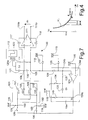
- a sensing circuit 30 comprises a sensing operational amplifier 20, a feedback stage 21, a compensation stage 31 and a signal generator 60, which is connectable to the common node 15 through a first input of a selector 61 and supplies a sensing voltage Vs.
- the sensing operational amplifier 20 having fully differential topology, has its inputs connected to the first and, respectively, to the second detection node 13, 14, is connected in a charge-integrator configuration, and supplies an output voltage Vo.
- the feedback stage 21 comprises an amplifying circuit 25 and a first and a second feedback capacitor 26, 27, having first terminals connected to an output 25a of the amplifying circuit 25 and second terminals connected to the first and, respectively, to the second detection node 13, 14.
- the amplifying circuit 25, has differential inputs connected to the first and, respectively, to the second detection node 13, 14, receives a reference voltage V REF on a reference input 25b and supplies a feedback voltage V FB on its output 25a.
- the compensation stage 31 has an input, connected to the output 25a of the amplifying circuit 25, and an output 31a, connectable to the common node 15 through a second input of the selector 61. Moreover the compensation stage 31 supplies a compensation voltage Vc, linked to the common detection capacity Cs of the sensor MEMS 1 approximately by an inverse proportional function, as explained in detail below.
- the compensation stage 31 comprises a memory capacitor 32, a decoupling stage 34, preferably an operational amplifier in follower configuration, and an inverting amplifier 35.
- the memory capacitor 32 has a first terminal connected to ground and a second terminal alternatively connectable to the output 25a of the amplifying circuit 25 and to the decoupling stage 33 through a first and, respectively, a second switch 36, 37, controlled in counterphase.
- the inverting amplifier 35 has an input terminal 35a connected to the output of the decoupling stage 33; and an output terminal forming the output 31a of the compensation stage 31 and supplying the compensation voltage Vc.
- the sensing circuit 30 exploits the fact that the common sensing capacitance Cs is, to a first approximation, linked to the compensation voltage Vc through an inverse proportionality relation.
- the feedback voltage V FB supplied by the amplifier circuit 25 assumes a value directly proportional to the overall sensing capacitance Cs, as also does the output voltage V o .
- the feedback voltage V FB is stored and then transferred to the compensation operational amplifier 35.
- the pattern of the compensation voltage Vc with respect to the variations in the common sensing capacitance Cs is a first-order approximation of a relation of inverse proportionality (see Figure 4, which also shows a curve Vc(inversely proportional to the common sensing capacitance Cs).
- Vc K/Cs where K is a constant of proportionality.
- the sensing circuit 30 has, however, some limitations, which are mainly due to the fact that a first-order approximation is made. Following upon this approximation, in fact, linearity errors may occur, especially when the spurious displacements of the mobile mass 4 are of a considerable amount. In this case, the compensation of the spurious displacements may be imprecise, and, moreover, distortions are introduced that degrade the performance of the sensing circuit.
- the aim of the present invention is to overcome the above-mentioned drawbacks.
- a method and a circuit are provided for detection of displacements by means of a micro-electromechanical sensor, as defined in Claim 1 and Claim 13 , respectively.
- number 100 designates a sensing circuit for a MEMS sensor 101, here of the differential input type.
- the MEMS sensor 101 per se known and having a stator 2 and a mobile mass 3 as shown in Figures 1 and 2, has a first input terminal 102 and a second input terminal 103, which are connected to the mobile mass 3, and a first output terminal 104 and a second output terminal 105, which are connected to the stator 2 and can be represented schematically by four equivalent sensing capacitors 107-110.
- a first equivalent sensing capacitor 107 having capacitance C11, is connected between the first input terminal 102 and the first output terminal 104; a second equivalent sensing capacitor 108, having capacitance C12, is connected between the first input terminal 102 and the second output terminal 105; a third equivalent sensing capacitor 109, having capacitance C21, is connected between the second input terminal 103 and the first output terminal 104; and a fourth equivalent sensing capacitor 110, having capacitance C22, is connected between the second input terminal 103 and the second output terminal 105.
- the capacitances of the sensors are all equal to a common sensing capacitance Cs.
- the sensing circuit 100 comprises a sensing operational amplifier 111, having fully differential topology, a driving stage 112, a feedback stage 114, and at least one reference line 115, which supplies a reference voltage Vref.
- the sensing operational amplifier 111 has a non-inverting input and an inverting input, which are respectively connected to the first output terminal 104 and to the second output terminal 105 of the MEMS sensor 101, and an inverting output 111a and a non-inverting output 111b, between which an output voltage Vo is supplied.
- a first feedback switch 116 is connected between the inputs of the operational amplifier 111.
- a first integration capacitor 117 is connected between the non-inverting input and the inverting output 111a, and a second integration capacitor 118 is connected between the inverting input and the non-inverting output 111b of the sensing operational amplifier 111, which is consequently in a charge-integrator configuration. Both of the integration capacitors 117, 118 have integration capacitance Ci.
- the driving stage 112 comprises a signal-generator circuit 120, which has an output 120a supplying a staircase sensing voltage Vs with steps of predetermined amplitude and duration, and a pair of driving capacitors 121, 122, which have driving capacitance Cd and present first terminals in common, connected to the output 120a of the signal-generator circuit 120, and second terminals, connected to the non-inverting input and, respectively, to the inverting input of the sensing operational amplifier 111.
- the feedback stage 114 comprises a feedback operational amplifier 124 and a holding capacitor 125 having holding capacitance Ch.
- the feedback operational amplifier 124 has a non-inverting input 124a connected to the reference line 115; an inverting input 124b connected to the second output terminal 105 of the MEMS sensor 101 via a second feedback switch 128 and to the reference line 115 via a first supply switch 126; and an output 124c which supplies a compensation voltage Vc.
- a second initialization switch 127 is connected between the reference line 115 and the second output terminal 105 of the MEMS sensor 101.
- the output 124c of the feedback operational amplifier 124 is connected to the reference line 115 via a third initialization switch 140, and is also connected to the first input terminal 102 and to the second input terminal 103 of the MEMS sensor 101 via a first driving switch 129 and via a second driving switch 130, respectively.
- the first input terminal 102 and the second input terminal 103 of the MEMS sensor 101 are in turn connected to the reference line 115 via a third driving switch 131 and a fourth driving switch 132.
- the holding capacitor 125 has a first terminal connected to the output 124c of the feedback operational amplifier 124 and a second terminal which can be selectively connected to the reference line 115, via a first holding switch 134, and to the inverting input 124b of the feedback operational amplifier 124, via a second holding switch 135.
- an initialization step is performed, during which the initialization switches 126, 127, 140, the feedback switches 116, 128, the third and fourth driving switches 131, 132, and the first holding switch 134 are closed, while the first and second driving switches 129, 130 and the second holding switch 135 are open ( Figure 5). Consequently, the input terminals 102, 103 and output terminals 104, 105 of the MEMS sensor 101 and the inputs 124a, 124b of the feedback operational amplifier 124 are set at the reference voltage Vref. Also the compensation voltage Vc at the output 124c of the feedback operational amplifier 124 is initially equal to the reference voltage Vref.
- the common sensing capacitance Cs is detected and stored .
- the initialization switches 126, 127, 140 and the third driving switch 131 are open, while the first driving switch 129 is closed.
- a negative-feedback loop 136 formed by the feedback operational amplifier 124 and by the first and second equivalent sensing capacitors 107, 108 is closed.
- the feedback operational amplifier 124 is in an inverting-amplifier configuration; in particular, the driving capacitors 121, 122 and the sensing capacitors 107, 108 respectively form input elements and feedback elements of the inverting amplifier.
- Vcd Vref + ⁇ Vc
- the variation in the compensation voltage ⁇ Vc which is inversely proportional to the common sensing capacitance Cs, as shown by relation (12), is stored by the holding capacitor 125.
- this value of the driving voltage Vcd is also fed on the first input terminal 102 of the MEMS sensor 101, which is directly connected to the output 124c of the feedback operational amplifier 124.
- the capacitive unbalancing ⁇ Cs is detected.
- the step of the sensing-voltage Vs terminates, and the feedback switches 116, 128, the first holding switch 129, and the first and fourth driving switches 129, 132 are opened, while the second holding switch 135, and the second driving switch 130 and the fourth driving switch 131 are closed ( Figure 7).
- the second feedback switch 128 is open, the negative-feedback loop 136 is open.
- switching of the holding switches 134, 135 enables feedback connection of the holding capacitor 125 between the inverting input 124b and the output 124c of the feedback operational amplifier 124. In this way, the charge on the holding capacitor 125 is conserved, and hence the compensation voltage Vc on the output 124c of the feedback operational amplifier 124 is kept at the driving voltage Vcd.
- the compensation voltage Vc is used for driving the MEMS sensor 101.
- the output 124c of the feedback operational amplifier 124 is disconnected from the first input terminal 102 and connected to the second input terminal 103 of the MEMS sensor 101. Consequently, the voltage on the first input terminal 102 of the MEMS sensor 101 switches from the driving value Vcd to the value of the reference voltage Vref. Instead, the voltage on the second input terminal 103 switches from the value of the reference voltage Vref to the driving value Vcd.
- voltage steps of opposite sign and of an amplitude equal to the variation in the compensation voltage ⁇ VC, and hence inversely proportional to the common sensing capacitance Cs are applied simultaneously to the input terminals 102, 103 of the MEMS sensor 101.
- the output voltage Vo is independent of the common sensing capacitance Cs, given that the capacitive unbalancing ⁇ Cs is directly proportional to the common sensing capacitance, and hence the errors due to spurious displacements of the mobile mass of the MEMS sensor 101 are substantially eliminated.
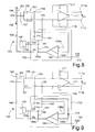
- FIGS 8 and 9 illustrate a different embodiment of the invention, according to which a sensing circuit 150 for a MEMS sensor 151 comprises the sensing operational amplifier 111, in a charge-integrator configuration, the reference line 115, the signal-generator circuit 120, a biasing line 165, which supplies a biasing voltage Vb, and a feedback stage 152.
- a sensing circuit 150 for a MEMS sensor 151 comprises the sensing operational amplifier 111, in a charge-integrator configuration, the reference line 115, the signal-generator circuit 120, a biasing line 165, which supplies a biasing voltage Vb, and a feedback stage 152.
- the MEMS sensor 151 in the present case of the single-input type described in Figures 1 and 2, has an input terminal 153 and a first output terminal 154 and a second output terminal 155, and may be schematically represented by a first equivalent sensing capacitor 156 and a second equivalent sensing capacitor 157.
- the first equivalent sensing capacitor 156 is connected between the input terminal 153 and the first output terminal 154 and has a capacitance equal to the common sensing capacitance Cs when the MEMS sensor 151 is at rest, and a capacitance equal to Cs + ⁇ Cs when the MEMS sensor 151 is excited and a capacitive unbalancing ⁇ Cs occurs.
- the second equivalent sensing capacitor 157 is connected between the input terminal 153 and the second output terminal 155 and has a capacitance equal to the common sensing capacitance Cs when the MEMS sensor 151 is at rest, and a capacitance equal to Cs - ⁇ Cs when the MEMS sensor 151 is excited.
- the feedback stage 152 comprises an amplifier circuit and a first feedback capacitor 159 and a second feedback capacitor 160.
- the amplifier circuit 158 has a pair of differential inputs 158a, 158b, respectively connected to the first output terminal 154 and to the second output terminal 155 of the MEMS sensor 151, a reference input connected to the reference line 115, and an output 158c, which supplies a feedback voltage Vfb and is connected to a feedback node 161 via a feedback switch 162 and to the input terminal 153 of the MEMS sensor 151 via a driving switch 164.
- the input terminal 153 of the MEMS sensor 151 is moreover connected to the driving line 165 via a biasing switch 166.
- the first feedback capacitor 159 and the second feedback capacitor 160 both of which having feedback capacitance Cfb, have first terminals connected to the feedback node 161 and second terminals respectively connected to the first output terminal 154 and to the second output terminal 155 of the MEMS sensor 151.
- the signal-generator circuit 120 which supplies a voltage step having amplitude Vs, has an output 120a, which is connected to the feedback node 161.
- the biasing switch 166 is opened, and the signal-generator circuit 120 supplies a voltage step having amplitude Vs.
- the driving switch 164 closes a first negative-feedback loop 168, which is formed by the amplifier circuit 158 and by the equivalent sensing capacitors 156, 157 of the MEMS sensor 151. Consequently, the voltage step of amplitude Vs brings about a variation ⁇ Vfb in the feedback voltage Vfb generated by the amplifier circuit 158, the operation of which is described in detail in the aforementioned article.
- Vfb Vb + ⁇ Vfb
- the input terminal 153 of the MEMS sensor 151 which is again connected to the biasing line 165, goes to the biasing voltage Vb.
- the voltage at the input terminal 153 undergoes an amplitude variation equal to the variation ⁇ Vfb of the feedback voltage Vfb, and hence a variation that is inversely proportional to the common sensing capacitance Cs.
- the sensing circuit described herein has not any problems of linearity, since no approximations are made, but rather the properties of the feedback amplifiers are exploited for generating a voltage which is in itself inversely proportional to the common sensing capacitance Cs. Consequently, the spurious displacements of the mobile mass of the MEMS sensor are effectively eliminated without introducing any distortions, and hence the precision of the sensing circuit is markedly improved.
Landscapes
- Physics & Mathematics (AREA)
- General Physics & Mathematics (AREA)
- Engineering & Computer Science (AREA)
- Power Engineering (AREA)
- Transmission And Conversion Of Sensor Element Output (AREA)
- Gyroscopes (AREA)
- Measurement Of The Respiration, Hearing Ability, Form, And Blood Characteristics Of Living Organisms (AREA)
Applications Claiming Priority (2)
| Application Number | Priority Date | Filing Date | Title |
|---|---|---|---|
| ITTO20010699 | 2001-07-17 | ||
| IT2001TO000699A ITTO20010699A1 (it) | 2001-07-17 | 2001-07-17 | Metodo e circuito di rilevamento di spostamenti tramite sensori micro-elettro-meccanici con compensazione di capacita' parassite e di movime |
Publications (3)
| Publication Number | Publication Date |
|---|---|
| EP1278068A2 true EP1278068A2 (fr) | 2003-01-22 |
| EP1278068A3 EP1278068A3 (fr) | 2003-08-20 |
| EP1278068B1 EP1278068B1 (fr) | 2010-04-21 |
Family
ID=11459059
Family Applications (1)
| Application Number | Title | Priority Date | Filing Date |
|---|---|---|---|
| EP02015859A Expired - Lifetime EP1278068B1 (fr) | 2001-07-17 | 2002-07-16 | Procédé et circuit de détection des déplacements utilisant des capteurs microélectromécaniques avec compensation de capacitances parasites |
Country Status (5)
| Country | Link |
|---|---|
| US (1) | US6753691B2 (fr) |
| EP (1) | EP1278068B1 (fr) |
| JP (1) | JP2003177142A (fr) |
| DE (1) | DE60236055D1 (fr) |
| IT (1) | ITTO20010699A1 (fr) |
Cited By (11)
| Publication number | Priority date | Publication date | Assignee | Title |
|---|---|---|---|---|
| WO2006103247A1 (fr) * | 2005-03-31 | 2006-10-05 | Stmicroelectronics S.R.L. | Dispositif permettant de commander la frequence de resonance d'un systeme micro-electromecanique oscillant |
| EP1790988A1 (fr) * | 2005-11-29 | 2007-05-30 | STMicroelectronics S.r.l. | Circuit de détection dans une interface de détection utilisant un capteur capacitif différentiel avec contrôle du mode commun à l'entrée |
| EP1811309A1 (fr) * | 2006-01-20 | 2007-07-25 | STMicroelectronics S.r.l. | Dispositif détecteur de chute libre et méthode de détection de chute libre |
| RU2308039C1 (ru) * | 2006-05-02 | 2007-10-10 | Государственное образовательное учреждение высшего профессионального образования Тульский государственный университет (ТулГУ) | Устройство для измерения ускорений |
| RU2338997C2 (ru) * | 2006-07-13 | 2008-11-20 | Федеральное государственное унитарное предприятие "Центральный научно-исследовательский институт "Электроприбор" | Способ измерения зазора между электродами и подвижной массой микромеханического устройства и устройство для его реализации |
| US7570066B2 (en) | 2007-11-01 | 2009-08-04 | Seagate Technology Llc | Simultaneous detection of in-plane and out-of-plane position displacement with capacitive sensors |
| RU2397498C1 (ru) * | 2009-02-04 | 2010-08-20 | Государственное образовательное учреждение высшего профессионального образования Тульский государственный университет (ТулГУ) | Компенсационный акселерометр |
| EP2653846A1 (fr) * | 2012-04-18 | 2013-10-23 | Nxp B.V. | Circuit de capteur et procédé d'étalonnage |
| EP2233890A3 (fr) * | 2009-02-11 | 2014-12-24 | Baumer Innotec AG | Capteur capacitif et procédé de détection capacitive de l'écartement d'un objet |
| US9307319B2 (en) | 2012-04-18 | 2016-04-05 | Nxp, B.V. | Sensor circuit and calibration method |
| DE102009026496B4 (de) | 2009-05-27 | 2022-04-28 | Robert Bosch Gmbh | Kompensationskapazität für einen kapazitiven Sensor |
Families Citing this family (25)
| Publication number | Priority date | Publication date | Assignee | Title |
|---|---|---|---|---|
| ITTO20010157A1 (it) * | 2001-02-21 | 2002-08-21 | St Microelectronics Srl | Metodo e circuito di rilevamento di spostamenti tramite sensori micro-elettro-meccanici con compensazione di capacita' parassite e di movime |
| ITTO20010705A1 (it) * | 2001-07-18 | 2003-01-18 | St Microelectronics Srl | Modulatore elettromeccanico a sovracampionamento autocalibrante e relativo metodo di autocalibrazione. |
| TWI221196B (en) * | 2001-09-06 | 2004-09-21 | Tokyo Electron Ltd | Impedance measuring circuit, its method, and electrostatic capacitance measuring circuit |
| FR2853472B1 (fr) * | 2003-04-01 | 2005-06-24 | St Microelectronics Sa | Circuit amplificateur audio |
| JP4499447B2 (ja) * | 2004-03-01 | 2010-07-07 | 日本電信電話株式会社 | 電子部品装置 |
| DE102004015122A1 (de) * | 2004-03-27 | 2005-10-13 | Robert Bosch Gmbh | Sensor mit integriertem Antriebs- und Detektionsmittel |
| JP4287324B2 (ja) * | 2004-04-28 | 2009-07-01 | 日本電信電話株式会社 | 電子部品装置 |
| RU2289789C1 (ru) * | 2005-09-23 | 2006-12-20 | Федеральное государственное унитарное предприятие "Центральный научно-исследовательский институт "Электроприбор" | Устройство измерения перемещения подвижной массы микромеханического гироскопа по оси первичных колебаний |
| RU2296301C1 (ru) * | 2005-09-23 | 2007-03-27 | Федеральное государственное унитарное предприятие "Центральный научно-исследовательский институт "Электроприбор" | Способ измерения перемещения подвижной массы микромеханического гироскопа по оси вторичных колебаний и устройство для реализации данного способа |
| JP3874366B1 (ja) * | 2006-03-16 | 2007-01-31 | 株式会社パワーシステム | キャパシタ蓄電装置 |
| FR2929055B1 (fr) * | 2008-03-19 | 2010-05-28 | Commissariat Energie Atomique | Systeme de conversion de charges en tension et procede de pilotage d'un tel systeme |
| US20090296979A1 (en) * | 2008-06-02 | 2009-12-03 | Hosiden Corporation | Speaker |
| US7956621B2 (en) * | 2008-06-11 | 2011-06-07 | Analog Devices, Inc. | Anti-capture method and apparatus for micromachined devices |
| US20100052701A1 (en) * | 2008-08-26 | 2010-03-04 | Seoul National University Industry Foundation | Nanoscale Displacement Transducer |
| US20120013351A1 (en) * | 2008-09-19 | 2012-01-19 | Physical Logic Ag | Method for converting a sensor capacitance under parasitic capacitance conditions and a capacitance-to-voltage converter circuit |
| DE102009000743B4 (de) * | 2009-02-10 | 2024-01-18 | Robert Bosch Gmbh | Vibrationskompensation für Drehratensensoren |
| JP5319368B2 (ja) | 2009-04-03 | 2013-10-16 | セミコンダクター・コンポーネンツ・インダストリーズ・リミテッド・ライアビリティ・カンパニー | コンデンサマイクの増幅回路 |
| TWI490456B (zh) * | 2011-04-29 | 2015-07-01 | Elan Microelectronics Corp | Differential Capacitance Sensing Circuit and Method |
| US8816703B2 (en) * | 2011-09-01 | 2014-08-26 | Robert Bosch Gmbh | Linear capacitance-to-voltage converter using a single amplifier for accelerometer front ends with cancellation of spurious forces contributed by sensor circuitry |
| JP5733277B2 (ja) * | 2012-07-13 | 2015-06-10 | 株式会社デンソー | 静電容量型センサの検出回路 |
| JP5733276B2 (ja) * | 2012-07-13 | 2015-06-10 | 株式会社デンソー | 静電容量型センサの検出回路 |
| CN103791928B (zh) * | 2012-10-31 | 2016-04-13 | 西门子公司 | 电容编码器的读出电路及方法 |
| DE102013218973B4 (de) * | 2013-09-20 | 2015-11-19 | Albert-Ludwigs-Universität Freiburg | Verfahren und Schaltung zur zeitkontinuierlichen Detektion der Position der Sensormasse bei gleichzeitiger Rückkopplung für kapazitive Sensoren |
| EP3862757B1 (fr) | 2020-02-07 | 2024-03-27 | Atlantic Inertial Systems Limited | Procédé de fonctionnement en boucle fermée d'accéléromètres capacitifs et de tels accéléromètres capacitifs |
| DE102020211325A1 (de) | 2020-09-09 | 2022-03-10 | Robert Bosch Gesellschaft mit beschränkter Haftung | Sensorsystem, umfassend ein mikromechanisches differentielles Sensorelement mit einer beweglichen Massenstruktur |
Family Cites Families (12)
| Publication number | Priority date | Publication date | Assignee | Title |
|---|---|---|---|---|
| US3585634A (en) * | 1968-07-31 | 1971-06-15 | Tyco Instr Division Inc | Cyclically operating analog to digital converter |
| US4054833A (en) * | 1976-06-11 | 1977-10-18 | Setra Systems, Inc. | Capacitance measuring system |
| US4389646A (en) * | 1980-04-30 | 1983-06-21 | Fuji Electric Co. Ltd. | Displacement converting circuit arrangement |
| US4860232A (en) * | 1987-04-22 | 1989-08-22 | Massachusetts Institute Of Technology | Digital technique for precise measurement of variable capacitance |
| US5095762A (en) * | 1988-07-14 | 1992-03-17 | University Of Hawaii | Multidimensional force sensor |
| US5417111A (en) * | 1990-08-17 | 1995-05-23 | Analog Devices, Inc. | Monolithic chip containing integrated circuitry and suspended microstructure |
| FR2706038B1 (fr) * | 1993-06-02 | 1995-07-21 | Suisse Electronique Microtech | Dispositif de mesure d'une force. |
| JPH0927722A (ja) * | 1995-07-12 | 1997-01-28 | Fuji Xerox Co Ltd | ゲイン可変増幅装置 |
| JP3125675B2 (ja) * | 1996-03-29 | 2001-01-22 | 三菱電機株式会社 | 容量型センサインターフェース回路 |
| US5992233A (en) * | 1996-05-31 | 1999-11-30 | The Regents Of The University Of California | Micromachined Z-axis vibratory rate gyroscope |
| US6316948B1 (en) * | 1998-07-01 | 2001-11-13 | Setra Systems, Inc. | Charge balance network with floating ground capacitive sensing |
| US6386032B1 (en) * | 1999-08-26 | 2002-05-14 | Analog Devices Imi, Inc. | Micro-machined accelerometer with improved transfer characteristics |
-
2001
- 2001-07-17 IT IT2001TO000699A patent/ITTO20010699A1/it unknown
-
2002
- 2002-07-16 DE DE60236055T patent/DE60236055D1/de not_active Expired - Lifetime
- 2002-07-16 EP EP02015859A patent/EP1278068B1/fr not_active Expired - Lifetime
- 2002-07-16 US US10/198,721 patent/US6753691B2/en not_active Expired - Lifetime
- 2002-07-17 JP JP2002208618A patent/JP2003177142A/ja active Pending
Cited By (15)
| Publication number | Priority date | Publication date | Assignee | Title |
|---|---|---|---|---|
| US7616078B2 (en) | 2005-03-31 | 2009-11-10 | Stmicroelectronics S.R.L. | Device for controlling the frequency of resonance of an oscillating micro-electromechanical system |
| EP1715580A1 (fr) * | 2005-03-31 | 2006-10-25 | STMicroelectronics S.r.l. | Dispositif pour commander la fréquence de résonance d'un système oscillateur micro-électromécanique |
| WO2006103247A1 (fr) * | 2005-03-31 | 2006-10-05 | Stmicroelectronics S.R.L. | Dispositif permettant de commander la frequence de resonance d'un systeme micro-electromecanique oscillant |
| EP1790988A1 (fr) * | 2005-11-29 | 2007-05-30 | STMicroelectronics S.r.l. | Circuit de détection dans une interface de détection utilisant un capteur capacitif différentiel avec contrôle du mode commun à l'entrée |
| US9201090B2 (en) | 2005-11-29 | 2015-12-01 | Stmicroelectronics S.R.L. | Detection circuit using a differential capacitive sensor with input-common-mode control in a sense interface |
| US7802476B2 (en) | 2006-01-20 | 2010-09-28 | Stmicroelectronics S.R.L. | Free fall detector device and free fall detection method |
| EP1811309A1 (fr) * | 2006-01-20 | 2007-07-25 | STMicroelectronics S.r.l. | Dispositif détecteur de chute libre et méthode de détection de chute libre |
| RU2308039C1 (ru) * | 2006-05-02 | 2007-10-10 | Государственное образовательное учреждение высшего профессионального образования Тульский государственный университет (ТулГУ) | Устройство для измерения ускорений |
| RU2338997C2 (ru) * | 2006-07-13 | 2008-11-20 | Федеральное государственное унитарное предприятие "Центральный научно-исследовательский институт "Электроприбор" | Способ измерения зазора между электродами и подвижной массой микромеханического устройства и устройство для его реализации |
| US7570066B2 (en) | 2007-11-01 | 2009-08-04 | Seagate Technology Llc | Simultaneous detection of in-plane and out-of-plane position displacement with capacitive sensors |
| RU2397498C1 (ru) * | 2009-02-04 | 2010-08-20 | Государственное образовательное учреждение высшего профессионального образования Тульский государственный университет (ТулГУ) | Компенсационный акселерометр |
| EP2233890A3 (fr) * | 2009-02-11 | 2014-12-24 | Baumer Innotec AG | Capteur capacitif et procédé de détection capacitive de l'écartement d'un objet |
| DE102009026496B4 (de) | 2009-05-27 | 2022-04-28 | Robert Bosch Gmbh | Kompensationskapazität für einen kapazitiven Sensor |
| EP2653846A1 (fr) * | 2012-04-18 | 2013-10-23 | Nxp B.V. | Circuit de capteur et procédé d'étalonnage |
| US9307319B2 (en) | 2012-04-18 | 2016-04-05 | Nxp, B.V. | Sensor circuit and calibration method |
Also Published As
| Publication number | Publication date |
|---|---|
| US20030052699A1 (en) | 2003-03-20 |
| JP2003177142A (ja) | 2003-06-27 |
| US6753691B2 (en) | 2004-06-22 |
| ITTO20010699A0 (it) | 2001-07-17 |
| EP1278068A3 (fr) | 2003-08-20 |
| ITTO20010699A1 (it) | 2003-01-17 |
| EP1278068B1 (fr) | 2010-04-21 |
| DE60236055D1 (de) | 2010-06-02 |
Similar Documents
| Publication | Publication Date | Title |
|---|---|---|
| EP1278068A2 (fr) | Procédé et circuit de détection des déplacements utilisant des capteurs microélectromécaniques avec compensation de capacitances parasites | |
| US6856144B2 (en) | Method and circuit for detecting movements through micro-electric-mechanical sensors, compensating parasitic capacitances and spurious movements | |
| EP1790988B1 (fr) | Circuit de détection dans une interface de détection utilisant un capteur capacitif différentiel avec contrôle du mode commun à l'entrée | |
| Lemkin et al. | A three-axis micromachined accelerometer with a CMOS position-sense interface and digital offset-trim electronics | |
| US6868726B2 (en) | Position sensing with improved linearity | |
| JP3125675B2 (ja) | 容量型センサインターフェース回路 | |
| US5661240A (en) | Sampled-data interface circuit for capacitive sensors | |
| US5977803A (en) | Capacitance type sensor interface circuit | |
| US8096179B2 (en) | Sensor device with reduced parasitic-induced error | |
| EP1715580B1 (fr) | Dispositif pour commander la fréquence de résonance d'un système oscillateur micro-électromécanique | |
| Yazdi et al. | An interface IC for a capacitive silicon/spl mu/g accelerometer | |
| WO2008008403A2 (fr) | Procédés et circuit de conditionnement de signal pour un capteur de pression de pneu intégré de captage capacitatif | |
| JP2003121457A (ja) | 容量式物理量センサ | |
| Yeh et al. | A low-power monolithic three-axis accelerometer with automatically sensor offset compensated and interface circuit | |
| Lee et al. | A capacitive-based accelerometer IC using injection-nulling switch technique | |
| US7055387B2 (en) | Apparatus for and method of sensing a measured input | |
| WO2015098893A1 (fr) | Circuit de réglage de capacité | |
| WO2022169956A1 (fr) | Appareils et systèmes d'accéléromètre pour le rejet de bruit | |
| JP3282360B2 (ja) | 容量型センサ | |
| Boser | Capacitive interfaces for monolithic integrated sensors | |
| Gómez et al. | Force-balance interface circuit based on floating MOSFET capacitors for micro-machined capacitive accelerometers | |
| Ungaretti et al. | Electronic Sensors Front-End | |
| US20240118307A1 (en) | Accelerometer having a grounded shield structure | |
| Chan et al. | A switched-capacitor interface circuit for integrated sensor applications | |
| JPH07218270A (ja) | 車両運動検出装置およびその検出感度調整方法 |
Legal Events
| Date | Code | Title | Description |
|---|---|---|---|
| PUAI | Public reference made under article 153(3) epc to a published international application that has entered the european phase |
Free format text: ORIGINAL CODE: 0009012 |
|
| AK | Designated contracting states |
Kind code of ref document: A2 Designated state(s): AT BE BG CH CY CZ DE DK EE ES FI FR GB GR IE IT LI LU MC NL PT SE SK TR |
|
| AX | Request for extension of the european patent |
Free format text: AL;LT;LV;MK;RO;SI |
|
| PUAL | Search report despatched |
Free format text: ORIGINAL CODE: 0009013 |
|
| AK | Designated contracting states |
Designated state(s): AT BE BG CH CY CZ DE DK EE ES FI FR GB GR IE IT LI LU MC NL PT SE SK TR |
|
| AX | Request for extension of the european patent |
Extension state: AL LT LV MK RO SI |
|
| RIC1 | Information provided on ipc code assigned before grant |
Ipc: 7G 01R 27/26 B Ipc: 7G 01D 5/24 B Ipc: 7G 01P 15/13 B Ipc: 7G 01P 15/125 A |
|
| 17P | Request for examination filed |
Effective date: 20040217 |
|
| AKX | Designation fees paid |
Designated state(s): DE FR GB IT |
|
| 17Q | First examination report despatched |
Effective date: 20090320 |
|
| GRAP | Despatch of communication of intention to grant a patent |
Free format text: ORIGINAL CODE: EPIDOSNIGR1 |
|
| GRAS | Grant fee paid |
Free format text: ORIGINAL CODE: EPIDOSNIGR3 |
|
| GRAA | (expected) grant |
Free format text: ORIGINAL CODE: 0009210 |
|
| RAP1 | Party data changed (applicant data changed or rights of an application transferred) |
Owner name: STMICROELECTRONICS SRL Owner name: HEWLETT-PACKARD COMPANY |
|
| AK | Designated contracting states |
Kind code of ref document: B1 Designated state(s): DE FR GB IT |
|
| REG | Reference to a national code |
Ref country code: GB Ref legal event code: FG4D |
|
| REF | Corresponds to: |
Ref document number: 60236055 Country of ref document: DE Date of ref document: 20100602 Kind code of ref document: P |
|
| PLBE | No opposition filed within time limit |
Free format text: ORIGINAL CODE: 0009261 |
|
| STAA | Information on the status of an ep patent application or granted ep patent |
Free format text: STATUS: NO OPPOSITION FILED WITHIN TIME LIMIT |
|
| 26N | No opposition filed |
Effective date: 20110124 |
|
| PGFP | Annual fee paid to national office [announced via postgrant information from national office to epo] |
Ref country code: GB Payment date: 20110701 Year of fee payment: 10 Ref country code: FR Payment date: 20110810 Year of fee payment: 10 |
|
| PGFP | Annual fee paid to national office [announced via postgrant information from national office to epo] |
Ref country code: IT Payment date: 20120627 Year of fee payment: 11 |
|
| GBPC | Gb: european patent ceased through non-payment of renewal fee |
Effective date: 20120716 |
|
| REG | Reference to a national code |
Ref country code: FR Ref legal event code: ST Effective date: 20130329 |
|
| PG25 | Lapsed in a contracting state [announced via postgrant information from national office to epo] |
Ref country code: FR Free format text: LAPSE BECAUSE OF NON-PAYMENT OF DUE FEES Effective date: 20120731 Ref country code: GB Free format text: LAPSE BECAUSE OF NON-PAYMENT OF DUE FEES Effective date: 20120716 |
|
| PG25 | Lapsed in a contracting state [announced via postgrant information from national office to epo] |
Ref country code: IT Free format text: LAPSE BECAUSE OF NON-PAYMENT OF DUE FEES Effective date: 20130716 |
|
| REG | Reference to a national code |
Ref country code: DE Ref legal event code: R082 Ref document number: 60236055 Country of ref document: DE Representative=s name: SCHMITT-NILSON SCHRAUD WAIBEL WOHLFROM PATENTA, DE |
|
| PGFP | Annual fee paid to national office [announced via postgrant information from national office to epo] |
Ref country code: DE Payment date: 20210622 Year of fee payment: 20 |
|
| REG | Reference to a national code |
Ref country code: DE Ref legal event code: R071 Ref document number: 60236055 Country of ref document: DE |