EP1278367A2 - Bildausgabegerät basierend auf einem Lichtquellen-Array mit individueller Helligkeitskorrektur für gleichmässige Bildqualität - Google Patents
Bildausgabegerät basierend auf einem Lichtquellen-Array mit individueller Helligkeitskorrektur für gleichmässige Bildqualität Download PDFInfo
- Publication number
- EP1278367A2 EP1278367A2 EP02015804A EP02015804A EP1278367A2 EP 1278367 A2 EP1278367 A2 EP 1278367A2 EP 02015804 A EP02015804 A EP 02015804A EP 02015804 A EP02015804 A EP 02015804A EP 1278367 A2 EP1278367 A2 EP 1278367A2
- Authority
- EP
- European Patent Office
- Prior art keywords
- light
- image
- intensity
- emitting elements
- light beams
- Prior art date
- Legal status (The legal status is an assumption and is not a legal conclusion. Google has not performed a legal analysis and makes no representation as to the accuracy of the status listed.)
- Withdrawn
Links
Images









Classifications
-
- G—PHYSICS
- G06—COMPUTING OR CALCULATING; COUNTING
- G06K—GRAPHICAL DATA READING; PRESENTATION OF DATA; RECORD CARRIERS; HANDLING RECORD CARRIERS
- G06K15/00—Arrangements for producing a permanent visual presentation of the output data, e.g. computer output printers
- G06K15/02—Arrangements for producing a permanent visual presentation of the output data, e.g. computer output printers using printers
- G06K15/12—Arrangements for producing a permanent visual presentation of the output data, e.g. computer output printers using printers by photographic printing, e.g. by laser printers
- G06K15/1238—Arrangements for producing a permanent visual presentation of the output data, e.g. computer output printers using printers by photographic printing, e.g. by laser printers simultaneously exposing more than one point
-
- H—ELECTRICITY
- H04—ELECTRIC COMMUNICATION TECHNIQUE
- H04N—PICTORIAL COMMUNICATION, e.g. TELEVISION
- H04N1/00—Scanning, transmission or reproduction of documents or the like, e.g. facsimile transmission; Details thereof
- H04N1/40—Picture signal circuits
- H04N1/401—Compensating positionally unequal response of the pick-up or reproducing head
- H04N1/4015—Compensating positionally unequal response of the pick-up or reproducing head of the reproducing head
-
- G—PHYSICS
- G06—COMPUTING OR CALCULATING; COUNTING
- G06K—GRAPHICAL DATA READING; PRESENTATION OF DATA; RECORD CARRIERS; HANDLING RECORD CARRIERS
- G06K2215/00—Arrangements for producing a permanent visual presentation of the output data
- G06K2215/0082—Architecture adapted for a particular function
- G06K2215/0085—Error recovery
Definitions
- the present invention relates to an image-forming apparatus in which a plurality of light-sources expose a photosensitive material to form an image on it, and specifically relates to an image-forming apparatus, which can prevent unevenness of the image by controlling the brightness of light-sources disposed at the both ends of the array of the plurality of light-sources.
- a color image-recording apparatus which produces a color proof for confirming image data utilized for forming an original plate of printing matters, etc.
- the image-forming apparatus which forms an image by exposing the photosensitive material with the plurality of light-sources.
- a plurality of light beams each of which is emitted from each of light-emitting elements having colors different each other, such as Read, Green, Blue, etc., are synthesized into one light-beam, which is irradiated onto the photosensitive material.
- Light emitting diodes hereinafter, referred to as LEDs
- semiconductor laser devices etc.
- the color image is formed by exposing the photosensitive material with the light beams irradiated from such the light-emitting elements, the light amounts of which are modulated in stepwise on the basis of image data.
- one of a plurality of light sources, into each of which light beams emitted from a plurality of light-emitting elements are synthesized is defined as one channel.
- the image-forming apparatus incorporates an optical unit in which a plurality of channels are arranged in a sub-scanning direction. Further, the optical unit exposes the photosensitive material, which is rotating in a main-scanning direction, by irradiating the light beams onto it to form the image.
- the optical unit moves a distance equivalent to the width of the light beam in the sub-scanning direction. Then, the light beams are irradiated onto next recording area to continuously conduct the image-exposing operation. Otherwise, it is applicable that movements in both main-scanning and sub-scanning direction are combined relative to each other. In this case, the optical unit spirally moves on the photosensitive material.
- a part of the photosensitive material, on which an image-exposing operation with the light beams is conducted during one main-scanning operation is defined as a recording area.
- a light beam, into which light beams emitted from a plurality of light-emitting elements, having colors different each other, are synthesized is defined as one channel.
- the image-forming apparatus having a plurality of channels there has been a problem that, since the beam profiles vary depending on mounting positions of the light-emitting elements in each channel and manufacturing errors, in angle, etc., of the light-emitting elements itself, image-unevenness are liable to occur when forming the image by irradiating the light beams onto the photosensitive material.
- each of the beam profiles emitted by each of the light-emitting elements has been adjusted by means of compensation lenses or position/angle adjusting functions, etc., provided for all of the light-emitting elements.
- the cost for employing the compensation lenses are incurred as an additional cost, resulting in an increase of the manufacturing cost of the image-forming apparatus itself.
- Section (a) of Fig. 11 shows a graph of distributions of the light beams irradiated from "n" channels of the optical unit in respect to the positional coordinate of each of "n” channels.
- the beam profiles irradiated onto the exposing surface of the photosensitive material are indicated at the upper section of Fig. 11.
- the center areas are denoted by dot 100-1, 100-2, ---, 100-n (hereinafter, totally denoted by "dots 100").
- dot 100-1 denotes the center area of the beam profile emitted from channel 1
- dot 100-n denotes the center area of the beam profile emitted from channel "n”.
- peripheral area 101-1, 101-2, ---, 101-n peripheral areas dispersed from dots 100 are denoted by peripheral area 101-1, 101-2, ---, 101-n (hereinafter, totally denoted by "peripheral areas 101"). Still further, in section (a) of Fig. 11, waveforms N1, N2, ---, Nn indicate light amount characteristics of channels 1, 2, ---, "n", respectively.
- each of peripheral areas 101 of the light beams irradiated from channels 2, 3, ---, "n-1" (hereinafter, referred to as central arrayed channels), excluding channels 1 and "n” (hereinafter, referred to as both-end channels) from "n" channels, overlaps with those of adjacent light beams located at both sides of it. Accordingly, the light amount of the light beams, irradiated onto the exposing surface of the photosensitive material from the central arrayed channels, becomes uniform.
- Section (b) of Fig. 11 shows a graph of color developing density of the photosensitive material exposed by the light beams irradiated from the optical unit in respect to the positional coordinate of each of "n" channels.
- the solid line indicates the density characteristics of material "a”
- the one dotted chain line indicates the density characteristics of material "b”.
- Materials "a” and “b” are photosensitive materials having material characteristics being different each other.
- Fig. 12 shows the material characteristics of materials "a” and "b".
- Density X indicates an optimum density for forming an image on the photosensitive material.
- a color of density X being an optimum density, is developed on both materials.
- Y' which is exposed on materials "a” and "b”
- a color of density X A is developed on material "a”
- a color of density X B is developed on material "b”.
- the densities of the developed color are different relative to each other depending on the difference between material characteristics of the photosensitive materials. Accordingly, as shown in sections (a) and (b) of Fig. 11, the densities of the images formed at both ends of the recording areas of materials "a” and “b” are different relative to each other, due to the decrease of the light amount exposed by the light beam. Thus, it has been a problem that density-unevenness, generated in the formed image, have degraded the final image quality.
- the light amount characteristics of the light beams emitted by the optical unit vary depending on the individuality of each optical unit, due to manufacturing variations occurred during the assembling process of the optical unit in the factory. In such the case, it is necessary to further apply the abovementioned countermeasure corresponding to the light amount characteristics of the individual optical unit, and it has been further difficult to practically apply the abovementioned countermeasure.
- a method for compensating the light amount of the light beams irradiated from both-end channels in response to a moving amount in the sub-scanning direction is set forth in Tokkaihei 10-181085 and is well-known as one of conventional technologies.
- This method requires a detecting circuit for detecting the moving amount in the sub-scanning direction, resulting in a complicated configuration of the image-forming apparatus.
- a method for changing an intensity of the laser beam with the compensating laser beams equipped for both-end channels in response to image data is set forth in Tokkaihei 6-198952 and is well-known as another one of conventional technologies.
- the intensities of the laser beams irradiated from both-end channels are too strong, it is impossible to subtract the intensity of the laser beam with the compensating laser beams.
- the first object of the present invention to provide an image-forming apparatus, in which an occurrence of density-unevenness in the image is prevented by compensating the light amount of each light source, or by compensating the light amount of each channel located at the both ends of the channel array. Further, it is the second object of the present invention to provide an image-forming method for reducing the image-unevenness, caused by moving errors in the sub-scanning direction, at an unnoticeable level without increasing the cost of the image-forming apparatus.
- the term of "light amount” is also referred to as “light-intensity” or “intensity”.
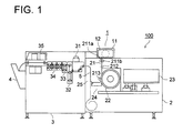
- Fig. 1 shows a configuration of image-forming apparatus 100 embodied in the present invention.
- Image-forming apparatus 100 is constituted mainly by paper loading section 1, exposing unit 2, developing process unit 3 and paper delivery tray 4.
- Paper loading section 1 is disposed at an upper position of exposing unit 2.
- Paper feeding cover 11 being capable of opening and closing, is mounted on paper loading section 1, in which exclusive cartridge 12, containing photosensitive material 5 (a recording medium) of rolled-shape, can be set.
- Paper feeding section 21, drum 22, optical unit 23, accumulating section 24 and paper ejecting section 25 constitute exposing unit 2, which performs the image-exposing operation for photosensitive material 5.
- Paper feeding section 21 comprises paper feeding rollers 211a, 211b, cutter 212 and paper feeding roller 213.
- Photosensitive material 5 set in paper loading section 1 is sandwiched between paper feeding rollers 211a, 211b, and fed to drum 22 by driving the rotating pair of paper feeding rollers 211a, 211b. Then, photosensitive material 5 is cut by cutter 212 when a predetermined length of photosensitive material 5 is fed to drum 22.
- Paper feeding roller 213 presses photosensitive material 5 onto drum 22, so as to prevent photosensitive material 5 from generating wrinkles when it is wound around drum 22.
- Photosensitive material 5, wound around drum 22, is exposed by the light beam irradiated from optical unit 23, while rotating in the main-scanning direction (namely, the rotating direction of drum 22).
- Optical unit 23 serving as a light source means, in which three light beams emitted from three individual light-emitting elements, such as Red-LED, Green-LED and Blue-LED, are synthesized into a single light beam through a mirror, a lens, etc., irradiates the synthesized light beam onto photosensitive material 5 wound around drum 22, while moving in an axial direction of drum 22 (the sub-scanning direction).
- three individual light-emitting elements such as Red-LED, Green-LED and Blue-LED
- photosensitive material 5, on which the image is already exposed is stored in a hanging state. Since the conveying velocity of photosensitive material 5 in developing process unit 3 is faster than that in exposing unit 2, the conveyance timings of photosensitive material 5 at both developing process unit 3 and exposing unit 2 are adjusted in accumulating section 24.
- Second exposing section 31, developing section 32, fixing section 33, stabilizing section 34 and drying section 35 constitute developing process unit 3, in which the image exposed on photosensitive material 5 is developed.
- second exposing section 31 a quasi-image is exposed on the non-exposed portion of photosensitive material 5, on which no image has been exposed in exposing unit 2.
- developing section 32, fixing section 33 and stabilizing section 34 developing processes are applied to photosensitive material 5 conveying through them.
- drying section 35 photosensitive material 5 having a developed image is dried, and then, ejected to paper delivery tray 4.
- Fig. 2 shows a perspective view of drum 22 and optical unit 23 in image-forming apparatus 100.
- Drum 22 on circumferential surface of which photosensitive material 5 is wound, rotates around a drum axis, and the rotating direction of drum 22 is defined as the main-scanning direction.
- optical unit 23 continuously moves in parallel to the drum axis from one end of photosensitive material 5, and the moving direction of optical unit 23 is defined as the sub-scanning direction.
- Optical unit 23 irradiates the light beam onto photosensitive material 5 wound around drum 22 while moving in the sub-scanning direction, so as to expose photosensitive material 5. Initially, the light beam irradiated by optical unit 23 exposes a part of photosensitive material 5 having width "a”. Then, during one revolution of drum 22, optical unit 23 moves a distance equivalent to width "a” in the sub-scanning direction. Accordingly, during next revolution of drum 22, a next part of photosensitive material 5 having width "b” will be exposed.
- the values of width "a” and width "b” are determined on the basis of a number of light sources arranged in optical unit 23 and a gap distance between the light sources.
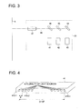
- Fig. 3 shows a configuration of optical unit 23.
- Optical unit 23 comprises light-source holding blocks 41, 42, 43, mirror 44, dichroic mirrors 45, 46, lens 47, etc.
- Each of the three light-emitting elements for instance, Red-LED, Green-LED and Blue-LED, is held in each of light-source holding blocks 41, 42, 43.
- the configuration of each of light-source holding blocks 41, 42, 43 will be detailed later.
- Mirror 44 reflects the first light beam irradiated from light-source holding block 43 toward lens 47.
- Dichroic mirror 45 reflects the second light beam irradiated from light-source holding block 42 toward lens 47, while the first light beam, irradiated from light-source holding block 43 and reflected by mirror 44, is transmitted through dichroic mirror 45.
- Dichroic mirror 46 reflects the third light beam irradiated from light-source holding block 41 toward lens 47, while the second light beam, irradiated from light-source holding block 42 and reflected by dichroic mirror 45, and the first light beam irradiated from light-source holding block 43 and transmitted through dichroic mirror 45, are transmitted through dichroic mirror 46.
- one dotted chain lines indicate traveling-locus of the three light beams.
- Fig. 4 shows an outlook appearance of light-source holding block 41. Since each outlook appearance of light-source holding blocks 42, 43 is the same as that of light-source holding block 41, only light-source holding block 41 will be detailed in the following.
- the light-emitting elements such as LEDs, etc., the number of which is the same as that of the channels, and each of which emits a light having a single uniform color, are mounted in light-source holding block 41.
- the light beams emitted from LEDs are irradiated toward an external area through light-beam irradiating holes 410-1, 410-2 ---, 410-n (hereinafter, totally referred to as light-beam irradiating holes 410), which are arranged in a lateral line.
- the light beam emitted by the LED disposed at channel #1 is irradiated toward an external area after passing through light-beam irradiating hole 410-1, and the light beam emitted by the LED disposed at channel #n is irradiated toward an external area after passing through light-beam irradiating hole 410-n.
- Fig. 13(a), Fig. 13(b) and Fig. 13(c) show graphs of luminous intensities of light beams in respect to the channel number, illustrating beam profiles of the light beams emitted from every channel.
- luminous intensities and beam profiles of the light beams in respect to channels #1 - #5 are substantially uniform. Since colors and densities of the image are developed on photosensitive material 5 in proportion to luminous intensities of the light beams, when the beam profiles, each corresponding to each of the channels, are uniform, it is possible to obtain a good quality image without having any image-unevenness formed on photosensitive material 5.
- the beam profiles of the LEDs are apt to vary even if luminous intensities of the light beams are uniform in respect to all channels. Further, the beam profiles of the LEDs also vary depending on the mounting errors of the LEDs, such as positions, angles, etc., occurring at the time when assembling light-source holding blocks 41, 42, 43 in the factory. Accordingly, variations of the beam profiles are generated between channels, as shown in Fig. 13(b) and Fig. 13(c).
- Fig. 13(c) shows a case that the beam profile of channel 3 is inclined to a direction toward channel 4.
- the color density of the part-area between channels 3 and 4 is intensified.
- color densities of part-areas, exposed by the light beams of both channels 3 and 4 are stronger than other part-areas in the image formed on photosensitive material 5.
- color densities of part-areas to be exposed by the light beam of channel 3 are weaker than other part-areas in the image formed on photosensitive material 5.
- unevenness of color densities are generated in the image formed on photosensitive material 5, resulting in the deterioration of the image quality.
- the light intensities of the light beams emitted from all of the channels are adjusted to the desired values, by adjusting an intensity of each of light beams emitted by the LEDs, based on compensation data derived from the characteristics of the LEDs employed for light-source holding blocks 41, 42, 43.
- the light intensities of the light beams emitted from all of the channels for the same desired density are adjusted to a uniform value, when commencing the exposing operation.
- the beam-pitch is defined as a distance between a center of light-beam irradiating hole 410-1 and a center of light-beam irradiating hole 410-n.
- the image-unevenness is generated in the image formed on photosensitive material 5 due to the variations of the optical characteristics of the light beams irradiated from optical unit 23.
- the density of the partial images, formed at the both end portions of the recording area of photosensitive material 5, would vary due to the difference between material characteristics of photosensitive materials 5. Owing to the above, the image-unevenness is generated in the image formed on photosensitive material 5, resulting in the deterioration of the image quality.
- the light intensities of the light beams emitted from both end channels are adjusted to an optimum value, based on compensation data derived from the material characteristics of photosensitive material 5, the beam-pitch characteristics of the light beams irradiated from optical unit 23, etc.
- the light-intensity compensation processing, for adjusting the intensities of the light beams emitted from both end channels and all of the channels, will be detailed in the following.
- controlling section 700 comprises CPU 600, RAM 601, ROM 602 serving as a memory means, and I/O ports 603, 604 through which various kinds of sensors and actuators are coupled to controlling section 700 and the actuators are controlled on the basis of information sent from the sensors.
- the initial values inherent to image-forming apparatus 100 are stored in RAM 601.
- Accumulator/close sensor S60, accumulator/open sensor S61, paper-feeding shutter/open sensor S62, cartridge presence-or-absence sensor S63, paper end sensor S64, cover/close detecting sensor S65, cover/lock detecting sensor S66, feed-roller press-contact position detecting sensor S67, feed-roller release position detecting sensor S68, drum-roller press-contact position detecting sensor S69, drum-roller release position detecting sensor S70, paper leading-edge reference position sensor S71, paper feeding amount detecting sensor S72, paper end detecting sensor S73, peeling nail release sensor S74, peeling nail intermediate sensor S75, peeling nail press-contact sensor S76, paper outlet sensor S77, peeling jam detecting sensor S78, cutter home-position detecting sensor S79, cutter end-position detecting sensor S80, outlet shutter/open detecting sensor S81, sub-scanning reference position detecting sensor S82, sub-scanning writing position detecting sensor S83 and sub-scanning overrun position detecting sensor S84 are
- Accumulator/open-close motor M60, paper-feeding shutter motor M61, cover/lock motor M62, feed-roller press-contact release motor M63, paper-feeding motor M64, drum-roller press-contact release motor M65, drum-roller driving motor M66, drum rotating motor M 67, peeling nail driving motor M68, outlet shutter driving motor M69, paper ejecting motor M70, sub-scanning conveyance motor M71 and cutter driving motor M72 are incorporated in image-forming apparatus 100 as the actuators, and are controllably driven by drivers D60, D61, D62, D63, D64, D65, D66, D67, D68, D69, D70, D72 and D73.
- LCD driver 74 controls liquid-crystal display panel 63 to display the operating statuses of image-forming apparatus 100, etc. on it. While, the operator can input various kinds of setting information from touch panel 62.
- Analogue-to-digital converting section 64 (hereinafter, referred to as A/D converting section 64) converts the setting information inputted by the operator to digital data, which are further inputted into CPU 600.
- the digital image data are inputted from raster image processor 65 (hereinafter, referred to as RIP 65) and further inputted into Y-data buffer 608Y, M-data buffer 608M, C-data buffer 608C and K-data buffer 608K (hereinafter, totally referred to as data buffer 608) through image data I/F section 605.
- RIP 65 raster image processor 65
- rotary encoder 60 sends the signals, based on the information for feeding photosensitive material 5, to PLL 606.
- dot clock generating section 607 outputs the dot clock signals to lookup table 609 (hereinafter, referred to as LUT 609).
- LUT 609 converts the digital image data, inputted from data buffer 608, to R, G, B image data, which are outputted to R-D/A converting section 610R, G-D/A converting section 610G and B-D/A converting section 610B (hereinafter, totally referred to as D/A converting section 610).
- D/A converting section 610 conducts the digital-to-analogue converting processing for the image data, and outputs the converted image signals to R-LED driver D611R, G-LED driver D611G and B-LED driver D611B (hereinafter, totally referred to as LED driver D611).
- LED driver D611 drives LEDs included in light-source holding blocks 41, 42, 43.
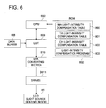
- Fig. 6 shows a partial block diagram extracted from the total block diagram of the configuration of image-forming apparatus 100 shown in Fig. 5. Referring to Fig. 6, the operations of the light-intensity compensation processing will be detailed in the following.
- CPU 600 retrieves light-intensity compensation program 803 from ROM 602 and stores them in RAM 601 to execute the program.
- LUT 609 converts the digital image data inputted from data buffer 608 to the R, G, B digital image data, which are outputted to CPU 600.
- CPU 600 applies the compensation processing to the R, G, B digital image data inputted from LUT 609 on the basis of MA light-intensity compensation table 800, TA light-intensity compensation table 801 and CH light-intensity compensation table 802.
- CPU 600 After the compensation processing is completed, CPU 600 outputs the compensated R, G, B digital image data to D/A converting section 610 to conduct the digital-to-analogue converting processing.
- the converted R, G, B image-signals are outputted to LED driver D611, which drive the LEDs included in light-source holding blocks 41, 42, 43, based on the R, G, B image-signals inputted.
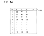
- Fig. 14 shows a data structure of CH light-intensity compensation table 802.
- the compensation data in respect to Red-LEDs, Green-LEDs and Blue-LEDs for each channel constitute CH light-intensity compensation table 802.
- the compensation data are determined as default data from measurements obtained by measuring characteristics of the light beams emitted from light-source holding blocks 41, 42, 43, and then, CH light-intensity compensation table 802 is stored in ROM 602, before shipping image-forming apparatus 100 from the factory.
- Fig. 15 shows a flowchart of the light-intensity compensation processing.
- LUT 609 converts the digital image data inputted from data buffer 608 to the R, G, B image data so as to determine a target light intensity, and then, outputs the converted R, G, B image data to CPU 600 (step A1).
- CPU 600 retrieves CH light-intensity compensation table 802 from ROM 602 (step A2). Then, CPU 600 applies the compensation processing to the R, G, B image data inputted from LUT 609, based on the data included in CH light-intensity compensation table 802, and then, outputs the compensated R, G, B image data to LUT 609 (step A3). Then, the light-intensity compensation processing is finalized.
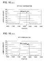
- Fig. 16(a) and Fig. 16(b) show graphs of intensity transients of light beams emitted from all over channels included in optical unit 23 embodied in the present invention.
- Intensity transient in case of not conducting the light-intensity compensation processing is indicated in Fig. 16(a)
- another intensity transient in case of conducting the light-intensity compensation processing is indicated in Fig. 16(b)
- the horizontal axis indicates positions in a sub-scanning direction.
- each of the graphs shown in Fig. 16(a) and Fig. 16(b) indicates a luminous intensity of the light beam when optical unit 23 is positioned in a range of position 11600 - 12400.
- the peak value located at position A is lower than that located at anyone of other positions. This indicates a fact that the peak of the beam profile irradiated from the channel located at position A is lower than that irradiated from each of the other channels.
- Such the variations of the beam profiles cause the image-unevenness when forming the image on photosensitive material 5.
- the graph shown in Fig. 16(b) indicates a result of applying the light-intensity compensation processing to all of the LEDs included in light-source holding blocks 41, 42, 43. Thanks to the light-intensity compensation processing, since there are no extraordinarily protruded peaks of luminous intensity on the graph shown in Fig. 16(b), the peak intensities of the beam profiles irradiated from all over the channels are substantially uniform. Further, since the intensities of the light beam emitted from all over the channels are in a range of 130 - 140, being an optimum intensity range for exposing photosensitive material 5, it becomes possible to form a good quality image on photosensitive material 5.
- the scope of the present invention is not limited to the contents of the abovementioned embodiment.
- the disclosed embodiment can be varied by a skilled person without departing from the spirit and scope of the invention.
- the light-intensity compensation processing is only applied to the specific LEDs, which irradiate the light beams, for exposing the color(s) of Cyan and/or Magenta except Yellow, onto photosensitive material 5.
- the light-intensity compensation processing can be applied to the specific LEDs only when irradiating the light beams for exposing the color(s) of Cyan and/or Magenta onto photosensitive material 5, without conducting the light-intensity compensation processing in respect to the light beams for exposing the color Yellow.
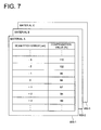
- Fig. 7 shows a data structure of MA light-intensity compensation table 800.
- MA light-intensity compensation table 800 serving as a data table, the compensation values of the intensities of the light beams emitted from the both-end channels are established, on the basis of beam pitch errors caused by the manufacturing variations of light-source holding blocks 41, 42, 43, etc.
- MA light-intensity compensation table 800 is further established in regard to every material characteristic of photosensitive material 5. For instance, MA light-intensity compensation tables 800-1, 800-2, 800-3 are established in regard to materials A, B, C, respectively.
- the individual material light-intensity compensation values for the light beams irradiated from the both channels are set at 80%, deriving from MA light-intensity compensation table 800-1.
- the beam pitch is widened by +3 ⁇ m compared to the normal beam pitch, the peripheral portion of "n"-th recording area overlaps with those of "n-1"-th and "n+1"-th recording areas on photosensitive material 5. For this reason, the color density of the portion where the exposing operations are duplicated becomes dense, resulting in the density-unevenness of the image. Accordingly, when the beam pitch is wider than the normal value, intensities of the light beams emitted from the both end channels are reduced.
- the individual material light-intensity compensation values for the light beams irradiated from the both channels are set at 110%, deriving from MA light-intensity compensation table 800-1.
- the beam pitch is shortened by -3 ⁇ m compared to the normal beam pitch, non-exposed portions or extraordinarily weak-exposed portions, located between "n"-th recording area and "n-1"-th and "n+1"-th recording areas, are generated in a main-scanning direction. For this reason, the color density of the weak-exposed portions becomes pale, resulting in the density-unevenness of the image. Accordingly, when the beam pitch is shorter than the normal value, intensities of the light beams emitted from the both end channels are increased.
- the data of MA light-intensity compensation table 800 obtained by measuring the characteristics of the light beams emitted from optical unit 23 during the assembling process of image-forming apparatus 100 in the factory, are stored in advance in ROM 602 for every kind of photosensitive material 5 to be employed for image-forming apparatus 100.
- Fig. 8 shows a data structure of TA light-intensity compensation table 801.
- the compensation values for the intensities of the light beams necessary for obtaining the desired density in the image formed on photosensitive material 5 (hereinafter, referred to as the target light intensity), are established in TA light-intensity compensation table 801 serving as a data table. Further, sometimes, the visualized pattern of the image-unevenness varies depending on the difference between the material characteristics in photosensitive material 5.
- the intensities of the light beams are compensated on the basis of the data stored in TA light-intensity compensation table 801, which is established on the basis of the measured values obtained by measuring the material characteristics of photosensitive material 5, and which is stored in ROM 602 in advance during the assembling process of image-forming apparatus 100 in the factory.
- Fig. 9 shows a data structure of CH light-intensity compensation table 802.
- the compensation values, for the target light intensity of the light beam emitted from each of channels, are stored in CH light-intensity compensation table 802.
- the data, established in CH light-intensity compensation table 802, are created during the executing process of light-intensity compensation program 803. The method for establishing such the data will be detailed later.
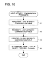
- Fig. 10 shows a flowchart of the light-intensity compensation processing.
- step A1 in accordance with a kind of material employed for photosensitive material 5, CPU 600 retrieves one of MA light-intensity compensation tables 800-1, 800-2 and 800-3 from ROM 602 and stores the retrieved one in RAM 601.
- the operator loads photosensitive material 5 into paper loading section 1, the operator inputs material-kind data for distinguishing the kind of material employed for photosensitive material 5 by means of touch panel 62.
- the inputted material-kind data are stored in RAM 601, so that CPU 600 can retrieve one of MA light-intensity compensation tables 800 by reading the material-kind data from RAM 601 in step A1.
- CPU 600 retrieves MA light-intensity compensation table 800-1 from ROM 602. Then, when the beam-pitch error is +3 ⁇ m, CPU 600 sets the material light-intensity compensation value at 80%, and stores the value in RAM 601.
- step A2 CPU 600 retrieves TA light-intensity compensation table 801 from ROM 602, and stores it in RAM 601. While, LUT 609 inputs the digital image data from data buffer 608 and converts them into the R, G, B image data to determine the target light-intensity. Then, CPU 600 establishes the target light-intensity compensation value by inputting the target light-intensity.
- CPU 600 sets the target light-intensity compensation value at 95%, deriving from TA light-intensity compensation table 801, and store it in RAM 601.
- step A3 CPU 600 establishes the data of CH light-intensity compensation table 802 in accordance with the material light-intensity compensation value and the target light-intensity compensation value respectively found in step A1 and step A2.
- the target light-intensity compensation value is 95%
- CPU 600 sets the target light-intensity for allover channels at 95%.
- the material light-intensity compensation value is 80%
- step 4 CPU 600 applies compensation processing to the digital image data inputted from LUT 609, on the basis of the compensation value stored in CH light-intensity compensation table 802, and then, outputs the compensated image data to LUT 609. Then, the light-intensity compensation processing is finalized.
- MA light-intensity compensation table 800 is established on the basis of material characteristics of photosensitive material 5 and the manufacturing variations of light-source holding blocks 41, 42, 43, while, CH light-intensity compensation table 802 is created by executing light-intensity compensation program 803. Further, the light-intensity of the light beams, emitted from the both end channels, is adjusted by conducting the light-intensity compensation processing for the light beam of each channel on the basis of the data included in the above tables. Accordingly, it becomes possible to reduce the image-unevenness in the image formed on photosensitive material 5.
- the light-intensities of the light beams are compensated on the basis of the data stored in TA light-intensity compensation table 801 so as to obtain a desired density in the exposing operation. Accordingly, it becomes possible to reduce the image-unevenness in the image formed on photosensitive material 5.
- the data of MA light-intensity compensation table 800 are defined as the default data, which is determined in advance at the factory. It is also applicable, however, that the operator can arbitrarily change the contents of the abovementioned data by inputting new data from touch panel 62. Further, by mounting a communicating section capable of performing bilateral data communication with an external apparatus in image-forming apparatus 100, it becomes possible to transmits a new MA light-intensity compensation table to the communicating section of image-forming apparatus 100 from the external apparatus through a network, etc., though this configuration is not shown in the drawings. Then, CPU 600 changes MA light-intensity compensation table 800 stored in ROM 602 to new MA light-intensity compensation table received from the external apparatus. Accordingly, even if photosensitive material 5, which is not registered in MA light-intensity compensation table 800, is employed, it becomes possible to conduct the light-intensity compensation processing by inputting new compensation values based on its material characteristics from an external environment.
- the light-intensity compensation processing is only applied to the LEDs, which expose colors of cyan and/or magenta excluding yellow and irradiate the light beams from the both end channels.
- the second embodiment is an image-forming apparatus, which produces a color proof utilized for checking image data serving as base data for the printing plate by exposing a color photosensitive material with a plurality of light beams having different wavelengths relative to each other based on dot-image data processed by RIP (Raster Image Processor) and sent from a host apparatus.
- RIP Raster Image Processor
- drum 503, on which photosensitive material 501 is wrapped is driven by a driving source (not shown in the drawings) so as to rotate it in a main-scanning direction.
- Guide 507 is arranged in the bus-line direction (the sub-scanning direction) of the drum 503 and exposing unit 509 driven by a driving source (not shown in the drawings) moves along guide 507.
- beam monitor 510 for detecting the light beam emitted from exposing unit 509 is disposed at a side space of drum 503.
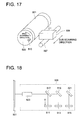
- Fig. 18 shows an internal configuration of exposing unit 509, viewing from the direction indicated by arrow I in Fig. 17.
- light source units 511, 513, 515 each of which emits a plurality of light beams, are arranged.
- light source units 511, 513, 515 correspond to R (Red color), G (Green color) and B (Blue color), respectively.
- the light beams, emitted from light source units 511, 513, are reflected by dichroic mirrors 517, 519, which transmit a part of the light and reflect another part of the light, while the light beam, emitted from light source unit 515, is reflected by reflection mirror 521, and then, these three light beams are converged onto photosensitive material 501 through converging-lens optical system 523.
- a plurality of LEDs 524 arranged in a line and holder 525 for holding LEDs 524 constitute light source unit 511.
- the digital image data are transmitted to data buffer 204 from RIP 200 externally coupled to the apparatus through image-data interface section 201.
- the digital image data are fed from data buffer 204 to driving sections D320, D321, D322, through LUT 205 (Look Up Table) and D/A converters 206 - 208, by the clocking actions of dot clock pulses generated by dot-clock generating section 203, so that driving sections D320, D321, D322 drive light source units 511, 513, 515, respectively.
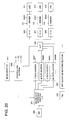
- the target light-intensity compensation table in which relations between densities and beam intensities are recorded, and the channel light-intensity compensation table, for forming an invisible unevenness with plural bars in the scanning lines, are stored.
- Numeral 1000 indicates a controlling section for controlling image-data interface section 201 and LUT 205.
- the dot image data for each color (C, M, Y, K) generated by RIP 200 are transferred to image-data interface section 201, in which the RIP format of the dot image data is converted to the other data-format utilized for exposing operation, and then, the converted dot image data are stored in data buffer 204.
- image data for forming an image of one sheet are accumulated in data buffer 204, all color images are simultaneously exposed.
- controlling section 1000 determines a target light intensity based on the data of the exposing format converted in image-data interface section 201.
- step 2 the target light intensity is compensated for based on the target light-intensity compensation table stored in LUT 205.
- step 3 the data, for forming the invisible unevenness with plural bars in the scanning lines, are read from the channel light-intensity compensation table stored in LUT 205.
- step 4 the channel light-intensity is determined.
- the channel light-intensity compensation data is established, so as to form the invisible unevenness with plural bars, having a density-difference substantially equivalent to that between the target density and the density of the overlapped area, in the main-scanning lines.
- the channel light-intensity compensation data is established, so as to intensify the intensity of the light beam irradiated onto a portion adjacent to the gap of the next main-scanning line, and so as to form the invisible unevenness with plural bars, having a density-difference substantially equivalent to that between the target density and the density of the portion, in the main-scanning lines.
- the channel light-intensity compensation data is established, so as to intensify the intensity of the light beam irradiated onto a portion adjacent to the gap of the next main-scanning line, and so as to form the invisible unevenness with plural bars, having a density-difference substantially equivalent to that between the target density and the density of the portion, in the main-scanning lines.
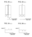
- the density-differences are intentionally formed between image-unevenness (the portions indicated by fine solid lines D) caused by the duplication of the main-scanning lines, so as to make the image-unevenness unnoticeable.
- step 5 the data for driving the light source are set.
- step 6 the light intensity is measured by means of beam monitor 510.
- controlling section 1000 determines whether or not the measured light intensity is equal to the target light intensity.
- step 8 when controlling section 1000 determines that the measured light intensity is equal to the target light intensity in step 7, the data for driving the light source is determined as it is.
- controlling section 1000 changes the data for driving the light source and returns to step 5 with the changed data.
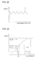
- the density, obtained by changing the intensity of the light beam is in a range of 70% - 130%, when the target density is set at 100%.
- Fig. 23 shows a relationship between a photosensitive material of general use and an exposing amount.
- the operation for determining the data for driving the light source as shown in Fig. 21 is performed in regard to each of the colors R, G, B in the second embodiment, it is also applicable that the abovementioned operation is performed only for the light component having a wavelength at which the image-unevenness is specifically noticeable.
- the wavelengths of the light beams emitted from the LEDs vary from one to another, and the densities in the recorded image also vary corresponding to the differences between the wavelengths. Accordingly, it is also applicable that the light intensity of each LED is compensated for by providing a light intensity compensation table corresponding to the differences between the wavelengths of the LEDs in LUT 205.
Landscapes
- Engineering & Computer Science (AREA)
- Physics & Mathematics (AREA)
- General Physics & Mathematics (AREA)
- Signal Processing (AREA)
- Optics & Photonics (AREA)
- General Engineering & Computer Science (AREA)
- Multimedia (AREA)
- Theoretical Computer Science (AREA)
- Printers Or Recording Devices Using Electromagnetic And Radiation Means (AREA)
- Laser Beam Printer (AREA)
- Facsimile Scanning Arrangements (AREA)
- Exposure Or Original Feeding In Electrophotography (AREA)
- Control Of Exposure In Printing And Copying (AREA)
Applications Claiming Priority (6)
| Application Number | Priority Date | Filing Date | Title |
|---|---|---|---|
| JP2001220244 | 2001-07-19 | ||
| JP2001220244 | 2001-07-19 | ||
| JP2002013010A JP2003211724A (ja) | 2002-01-22 | 2002-01-22 | 画像形成装置 |
| JP2002013010 | 2002-01-22 | ||
| JP2002021551 | 2002-01-30 | ||
| JP2002021551A JP2003222964A (ja) | 2002-01-30 | 2002-01-30 | 画像形成装置 |
Publications (2)
| Publication Number | Publication Date |
|---|---|
| EP1278367A2 true EP1278367A2 (de) | 2003-01-22 |
| EP1278367A3 EP1278367A3 (de) | 2004-07-28 |
Family
ID=27347195
Family Applications (1)
| Application Number | Title | Priority Date | Filing Date |
|---|---|---|---|
| EP02015804A Withdrawn EP1278367A3 (de) | 2001-07-19 | 2002-07-15 | Bildausgabegerät basierend auf einem Lichtquellen-Array mit individueller Helligkeitskorrektur für gleichmässige Bildqualität |
Country Status (2)
| Country | Link |
|---|---|
| US (1) | US7030899B2 (de) |
| EP (1) | EP1278367A3 (de) |
Cited By (2)
| Publication number | Priority date | Publication date | Assignee | Title |
|---|---|---|---|---|
| EP1607902A1 (de) * | 2004-06-18 | 2005-12-21 | Océ-Technologies B.V. | Einstellung der Belichtungsenergie in einem LED Drucker |
| US7791629B2 (en) | 2004-06-18 | 2010-09-07 | Océ-Technologies B.V. | Exposure device, printing apparatus employing an exposure device and method for adjusting a non-impact printing apparatus |
Families Citing this family (17)
| Publication number | Priority date | Publication date | Assignee | Title |
|---|---|---|---|---|
| US20040101954A1 (en) | 2002-11-27 | 2004-05-27 | Graessle Josef A. | Back side plate illumination for biological growth plate scanner |
| US7351574B2 (en) * | 2002-11-27 | 2008-04-01 | 3M Innovative Properties Company | Loading and ejection systems for biological growth plate scanner |
| US20040102903A1 (en) * | 2002-11-27 | 2004-05-27 | Graessle Josef A. | Biological growth plate scanner |
| US20040114026A1 (en) * | 2002-12-12 | 2004-06-17 | Hirohito Kondo | Image forming apparatus |
| US7298886B2 (en) * | 2003-09-05 | 2007-11-20 | 3M Innovative Properties Company | Counting biological agents on biological growth plates |
| US7576509B2 (en) * | 2003-09-10 | 2009-08-18 | Ricoh Company, Limited | Drive control method, drive control device, belt apparatus, image forming apparatus, image reading apparatus, computer product |
| JP2005094219A (ja) * | 2003-09-16 | 2005-04-07 | Rohm Co Ltd | 画像撮影装置 |
| US20050134677A1 (en) * | 2003-12-04 | 2005-06-23 | Shinpei Kawasaki | Image-forming apparatus |
| US7446793B2 (en) * | 2006-03-14 | 2008-11-04 | Kabushiki Kaisha Toshiba | Image forming apparatus |
| JP4912006B2 (ja) * | 2006-03-24 | 2012-04-04 | 大日本スクリーン製造株式会社 | 画像記録装置 |
| US7534025B2 (en) * | 2006-08-25 | 2009-05-19 | Philips Lumiled Lighting Company, Llc | Thin backlight with flipped light emitting diode |
| JP2008193268A (ja) * | 2007-02-01 | 2008-08-21 | Seiko Epson Corp | 画像生成装置、画像生成方法およびプログラム |
| US8417013B2 (en) * | 2008-03-04 | 2013-04-09 | 3M Innovative Properties Company | Information management in automated processing of biological growth media |
| US9933446B2 (en) * | 2008-03-04 | 2018-04-03 | 3M Innovative Properties Company | Processing of biological growth media based on measured manufacturing characteristics |
| US7995086B2 (en) * | 2008-10-22 | 2011-08-09 | Kabushiki Kaisha Toshiba | Image forming apparatus, image forming method and image processing apparatus |
| JP5744391B2 (ja) * | 2009-11-27 | 2015-07-08 | キヤノン株式会社 | 画像形成装置 |
| JP2011258796A (ja) * | 2010-06-10 | 2011-12-22 | Ricoh Co Ltd | レーザ駆動装置、光走査装置並びに画像形成装置 |
Family Cites Families (9)
| Publication number | Priority date | Publication date | Assignee | Title |
|---|---|---|---|---|
| JP2837683B2 (ja) | 1989-04-17 | 1998-12-16 | 富士写真フイルム株式会社 | 画像記録装置の画素ライン間隔補正方法 |
| JPH05198952A (ja) | 1992-01-21 | 1993-08-06 | Hitachi Ltd | 凹凸表面平坦化方法及びその装置 |
| EP0629974B1 (de) | 1993-06-18 | 2000-08-09 | Xeikon Nv | Anschlaglaser Drucker mit Gleichmässigkeitskorrektur |
| US5739841A (en) | 1995-12-28 | 1998-04-14 | Eastman Kodak Company | Apparatus and method for grey level printing with uniformity correction |
| JPH10181081A (ja) * | 1996-12-24 | 1998-07-07 | Oki Data:Kk | Ledヘッドの光量補正方法 |
| JPH10181085A (ja) | 1996-12-25 | 1998-07-07 | Fuji Photo Film Co Ltd | 画像露光装置の光量制御方法 |
| US6172700B1 (en) | 1997-01-16 | 2001-01-09 | Ricoh Company, Ltd. | Writing device for an image forming apparatus |
| JPH11129541A (ja) * | 1997-08-28 | 1999-05-18 | Konica Corp | 画像形成装置 |
| JP3845694B2 (ja) | 1998-04-01 | 2006-11-15 | ノーリツ鋼機株式会社 | 画像記録装置 |
-
2002
- 2002-07-10 US US10/192,581 patent/US7030899B2/en not_active Expired - Fee Related
- 2002-07-15 EP EP02015804A patent/EP1278367A3/de not_active Withdrawn
Cited By (2)
| Publication number | Priority date | Publication date | Assignee | Title |
|---|---|---|---|---|
| EP1607902A1 (de) * | 2004-06-18 | 2005-12-21 | Océ-Technologies B.V. | Einstellung der Belichtungsenergie in einem LED Drucker |
| US7791629B2 (en) | 2004-06-18 | 2010-09-07 | Océ-Technologies B.V. | Exposure device, printing apparatus employing an exposure device and method for adjusting a non-impact printing apparatus |
Also Published As
| Publication number | Publication date |
|---|---|
| EP1278367A3 (de) | 2004-07-28 |
| US7030899B2 (en) | 2006-04-18 |
| US20030016406A1 (en) | 2003-01-23 |
Similar Documents
| Publication | Publication Date | Title |
|---|---|---|
| US7030899B2 (en) | Image-forming apparatus having function of preventing unevenness of image formed on recording medium | |
| JP4079301B2 (ja) | 多書込み用ビーム源を有する光学式画像化ヘッド | |
| US9665031B2 (en) | Image forming apparatus that forms latent image by irradiating photosensitive member with light | |
| US8957928B2 (en) | Image forming apparatus | |
| US6426767B1 (en) | Image forming apparatus for maintaining a constant beam scanning state | |
| US7542168B2 (en) | Gradation conversion calibration by comparing grayscale and color chart measurements to target values and repeated correction amount calculations to tolerance values | |
| US20100296822A1 (en) | Image forming apparatus | |
| US20110182599A1 (en) | Image forming apparatus, alignment correcting method, and alignment correcting program | |
| JP2993556B2 (ja) | カラー画像出力装置 | |
| JP3769895B2 (ja) | 画像形成装置 | |
| JP2003266761A (ja) | 画像形成装置 | |
| JP2001138597A (ja) | レーザプリンタのカスタマイズされた画像作成のための媒体マッピング方法 | |
| JP2020008542A (ja) | 検査装置、検査方法、及びプログラム | |
| US20060033965A1 (en) | Image reading apparatus, image forming apparatus and image reading method | |
| US20060017944A1 (en) | Image forming apparatus | |
| JP6551792B2 (ja) | 画像読取装置、画像読取方法及び画像形成装置 | |
| JP2650761B2 (ja) | 画像記録装置 | |
| JPH0985984A (ja) | 画像形成装置および画像形成方法 | |
| KR200258635Y1 (ko) | 레이저 프린터의 축소 인쇄 구현장치 | |
| JP2018034374A (ja) | 画像形成装置及び画像形成制御プログラム | |
| JP2003182151A (ja) | 画像濃度調整方法及び画像形成装置 | |
| JP4534149B2 (ja) | プリント装置 | |
| JP2002019188A (ja) | サーマルプリンタ及び記録紙 | |
| JP2005328523A (ja) | 回折モジュレーターを有するプレートセッター内の画像処理のアーチファクトの減少 | |
| JP2003112447A (ja) | 画像形成方法及び装置 |
Legal Events
| Date | Code | Title | Description |
|---|---|---|---|
| PUAI | Public reference made under article 153(3) epc to a published international application that has entered the european phase |
Free format text: ORIGINAL CODE: 0009012 |
|
| AK | Designated contracting states |
Kind code of ref document: A2 Designated state(s): AT BE BG CH CY CZ DE DK EE ES FI FR GB GR IE IT LI LU MC NL PT SE SK TR |
|
| AX | Request for extension of the european patent |
Free format text: AL;LT;LV;MK;RO;SI |
|
| PUAL | Search report despatched |
Free format text: ORIGINAL CODE: 0009013 |
|
| AK | Designated contracting states |
Kind code of ref document: A3 Designated state(s): AT BE BG CH CY CZ DE DK EE ES FI FR GB GR IE IT LI LU MC NL PT SE SK TR |
|
| AX | Request for extension of the european patent |
Extension state: AL LT LV MK RO SI |
|
| RIC1 | Information provided on ipc code assigned before grant |
Ipc: 7G 06K 15/12 B Ipc: 7H 04N 1/401 A |
|
| 17P | Request for examination filed |
Effective date: 20050128 |
|
| AKX | Designation fees paid |
Designated state(s): DE FR GB |
|
| 17Q | First examination report despatched |
Effective date: 20050330 |
|
| GRAP | Despatch of communication of intention to grant a patent |
Free format text: ORIGINAL CODE: EPIDOSNIGR1 |
|
| STAA | Information on the status of an ep patent application or granted ep patent |
Free format text: STATUS: THE APPLICATION IS DEEMED TO BE WITHDRAWN |
|
| 18D | Application deemed to be withdrawn |
Effective date: 20060822 |