EP1278663B1 - Sicherheitsgurtspannungssensor - Google Patents
Sicherheitsgurtspannungssensor Download PDFInfo
- Publication number
- EP1278663B1 EP1278663B1 EP01928655A EP01928655A EP1278663B1 EP 1278663 B1 EP1278663 B1 EP 1278663B1 EP 01928655 A EP01928655 A EP 01928655A EP 01928655 A EP01928655 A EP 01928655A EP 1278663 B1 EP1278663 B1 EP 1278663B1
- Authority
- EP
- European Patent Office
- Prior art keywords
- housing
- sensor
- magnet
- cable anchor
- cable
- Prior art date
- Legal status (The legal status is an assumption and is not a legal conclusion. Google has not performed a legal analysis and makes no representation as to the accuracy of the status listed.)
- Expired - Lifetime
Links
- 230000013011 mating Effects 0.000 claims description 2
- 230000007812 deficiency Effects 0.000 description 2
- 230000007246 mechanism Effects 0.000 description 2
- 238000000034 method Methods 0.000 description 2
- 230000005355 Hall effect Effects 0.000 description 1
- 238000005266 casting Methods 0.000 description 1
- 230000006835 compression Effects 0.000 description 1
- 238000007906 compression Methods 0.000 description 1
- 230000003750 conditioning effect Effects 0.000 description 1
- 238000002788 crimping Methods 0.000 description 1
- 238000005242 forging Methods 0.000 description 1
- 238000009434 installation Methods 0.000 description 1
- 239000000463 material Substances 0.000 description 1
- 239000002184 metal Substances 0.000 description 1
- 230000002093 peripheral effect Effects 0.000 description 1
- 230000036316 preload Effects 0.000 description 1
- 239000003380 propellant Substances 0.000 description 1
- 238000000926 separation method Methods 0.000 description 1
- 230000007704 transition Effects 0.000 description 1
- 238000003466 welding Methods 0.000 description 1
Images




Classifications
-
- G—PHYSICS
- G01—MEASURING; TESTING
- G01L—MEASURING FORCE, STRESS, TORQUE, WORK, MECHANICAL POWER, MECHANICAL EFFICIENCY, OR FLUID PRESSURE
- G01L5/00—Apparatus for, or methods of, measuring force, work, mechanical power, or torque, specially adapted for specific purposes
- G01L5/04—Apparatus for, or methods of, measuring force, work, mechanical power, or torque, specially adapted for specific purposes for measuring tension in flexible members, e.g. ropes, cables, wires, threads, belts or bands
- G01L5/10—Apparatus for, or methods of, measuring force, work, mechanical power, or torque, specially adapted for specific purposes for measuring tension in flexible members, e.g. ropes, cables, wires, threads, belts or bands using electrical means
- G01L5/108—Apparatus for, or methods of, measuring force, work, mechanical power, or torque, specially adapted for specific purposes for measuring tension in flexible members, e.g. ropes, cables, wires, threads, belts or bands using electrical means for measuring a reaction force applied on a single support, e.g. a glider
-
- B—PERFORMING OPERATIONS; TRANSPORTING
- B60—VEHICLES IN GENERAL
- B60R—VEHICLES, VEHICLE FITTINGS, OR VEHICLE PARTS, NOT OTHERWISE PROVIDED FOR
- B60R22/00—Safety belts or body harnesses in vehicles
- B60R22/12—Construction of belts or harnesses
- B60R22/16—Construction of belts or harnesses using belts which become permanently deformed, i.e. one time use
-
- B—PERFORMING OPERATIONS; TRANSPORTING
- B60—VEHICLES IN GENERAL
- B60R—VEHICLES, VEHICLE FITTINGS, OR VEHICLE PARTS, NOT OTHERWISE PROVIDED FOR
- B60R22/00—Safety belts or body harnesses in vehicles
- B60R22/18—Anchoring devices
-
- B—PERFORMING OPERATIONS; TRANSPORTING
- B60—VEHICLES IN GENERAL
- B60R—VEHICLES, VEHICLE FITTINGS, OR VEHICLE PARTS, NOT OTHERWISE PROVIDED FOR
- B60R22/00—Safety belts or body harnesses in vehicles
- B60R22/48—Control systems, alarms, or interlock systems, for the correct application of the belt or harness
-
- G—PHYSICS
- G01—MEASURING; TESTING
- G01L—MEASURING FORCE, STRESS, TORQUE, WORK, MECHANICAL POWER, MECHANICAL EFFICIENCY, OR FLUID PRESSURE
- G01L5/00—Apparatus for, or methods of, measuring force, work, mechanical power, or torque, specially adapted for specific purposes
- G01L5/04—Apparatus for, or methods of, measuring force, work, mechanical power, or torque, specially adapted for specific purposes for measuring tension in flexible members, e.g. ropes, cables, wires, threads, belts or bands
- G01L5/10—Apparatus for, or methods of, measuring force, work, mechanical power, or torque, specially adapted for specific purposes for measuring tension in flexible members, e.g. ropes, cables, wires, threads, belts or bands using electrical means
- G01L5/101—Apparatus for, or methods of, measuring force, work, mechanical power, or torque, specially adapted for specific purposes for measuring tension in flexible members, e.g. ropes, cables, wires, threads, belts or bands using electrical means using sensors inserted into the flexible member
-
- G—PHYSICS
- G01—MEASURING; TESTING
- G01L—MEASURING FORCE, STRESS, TORQUE, WORK, MECHANICAL POWER, MECHANICAL EFFICIENCY, OR FLUID PRESSURE
- G01L5/00—Apparatus for, or methods of, measuring force, work, mechanical power, or torque, specially adapted for specific purposes
- G01L5/04—Apparatus for, or methods of, measuring force, work, mechanical power, or torque, specially adapted for specific purposes for measuring tension in flexible members, e.g. ropes, cables, wires, threads, belts or bands
- G01L5/10—Apparatus for, or methods of, measuring force, work, mechanical power, or torque, specially adapted for specific purposes for measuring tension in flexible members, e.g. ropes, cables, wires, threads, belts or bands using electrical means
- G01L5/103—Apparatus for, or methods of, measuring force, work, mechanical power, or torque, specially adapted for specific purposes for measuring tension in flexible members, e.g. ropes, cables, wires, threads, belts or bands using electrical means using sensors fixed at one end of the flexible member
-
- B—PERFORMING OPERATIONS; TRANSPORTING
- B60—VEHICLES IN GENERAL
- B60R—VEHICLES, VEHICLE FITTINGS, OR VEHICLE PARTS, NOT OTHERWISE PROVIDED FOR
- B60R22/00—Safety belts or body harnesses in vehicles
- B60R22/18—Anchoring devices
- B60R2022/1806—Anchoring devices for buckles
-
- B—PERFORMING OPERATIONS; TRANSPORTING
- B60—VEHICLES IN GENERAL
- B60R—VEHICLES, VEHICLE FITTINGS, OR VEHICLE PARTS, NOT OTHERWISE PROVIDED FOR
- B60R22/00—Safety belts or body harnesses in vehicles
- B60R22/48—Control systems, alarms, or interlock systems, for the correct application of the belt or harness
- B60R2022/4808—Sensing means arrangements therefor
- B60R2022/4841—Sensing means arrangements therefor for sensing belt tension
-
- B—PERFORMING OPERATIONS; TRANSPORTING
- B60—VEHICLES IN GENERAL
- B60R—VEHICLES, VEHICLE FITTINGS, OR VEHICLE PARTS, NOT OTHERWISE PROVIDED FOR
- B60R21/00—Arrangements or fittings on vehicles for protecting or preventing injuries to occupants or pedestrians in case of accidents or other traffic risks
- B60R21/01—Electrical circuits for triggering passive safety arrangements, e.g. airbags, safety belt tighteners, in case of vehicle accidents or impending vehicle accidents
- B60R21/015—Electrical circuits for triggering passive safety arrangements, e.g. airbags, safety belt tighteners, in case of vehicle accidents or impending vehicle accidents including means for detecting the presence or position of passengers, passenger seats or child seats, and the related safety parameters therefor, e.g. speed or timing of airbag inflation in relation to occupant position or seat belt use
- B60R21/01512—Passenger detection systems
- B60R21/01544—Passenger detection systems detecting seat belt parameters, e.g. length, tension or height-adjustment
-
- B—PERFORMING OPERATIONS; TRANSPORTING
- B60—VEHICLES IN GENERAL
- B60R—VEHICLES, VEHICLE FITTINGS, OR VEHICLE PARTS, NOT OTHERWISE PROVIDED FOR
- B60R21/00—Arrangements or fittings on vehicles for protecting or preventing injuries to occupants or pedestrians in case of accidents or other traffic risks
- B60R21/01—Electrical circuits for triggering passive safety arrangements, e.g. airbags, safety belt tighteners, in case of vehicle accidents or impending vehicle accidents
- B60R21/015—Electrical circuits for triggering passive safety arrangements, e.g. airbags, safety belt tighteners, in case of vehicle accidents or impending vehicle accidents including means for detecting the presence or position of passengers, passenger seats or child seats, and the related safety parameters therefor, e.g. speed or timing of airbag inflation in relation to occupant position or seat belt use
- B60R21/01512—Passenger detection systems
- B60R21/01544—Passenger detection systems detecting seat belt parameters, e.g. length, tension or height-adjustment
- B60R21/0155—Passenger detection systems detecting seat belt parameters, e.g. length, tension or height-adjustment sensing belt tension
-
- B—PERFORMING OPERATIONS; TRANSPORTING
- B60—VEHICLES IN GENERAL
- B60R—VEHICLES, VEHICLE FITTINGS, OR VEHICLE PARTS, NOT OTHERWISE PROVIDED FOR
- B60R22/00—Safety belts or body harnesses in vehicles
- B60R22/18—Anchoring devices
- B60R22/195—Anchoring devices with means to tension the belt in an emergency, e.g. means of the through-anchor or splitted reel type
- B60R22/1952—Transmission of tensioning power by cable; Return motion locking means therefor
-
- Y—GENERAL TAGGING OF NEW TECHNOLOGICAL DEVELOPMENTS; GENERAL TAGGING OF CROSS-SECTIONAL TECHNOLOGIES SPANNING OVER SEVERAL SECTIONS OF THE IPC; TECHNICAL SUBJECTS COVERED BY FORMER USPC CROSS-REFERENCE ART COLLECTIONS [XRACs] AND DIGESTS
- Y10—TECHNICAL SUBJECTS COVERED BY FORMER USPC
- Y10T—TECHNICAL SUBJECTS COVERED BY FORMER US CLASSIFICATION
- Y10T24/00—Buckles, buttons, clasps, etc.
- Y10T24/45—Separable-fastener or required component thereof [e.g., projection and cavity to complete interlock]
- Y10T24/45225—Separable-fastener or required component thereof [e.g., projection and cavity to complete interlock] including member having distinct formations and mating member selectively interlocking therewith
- Y10T24/45602—Receiving member includes either movable connection between interlocking components or variable configuration cavity
- Y10T24/45623—Receiving member includes either movable connection between interlocking components or variable configuration cavity and operator therefor
Definitions
- the inventions relates to a sensor for measuring a force or tension on an anchor point and a seat belt buckle.
- a force, or tension, sensor that senses the tension, or force, in a seat belt can more accurately indicate the size of an occupant, child seat, etc. in the vehicle seat.
- Such a force or tension sensing mechanism can also be used to determine that the seat belt is properly tightened about the seat occupant or child safety seat.
- a force sensor for generating a signal indicative of the usage of a seat belt as set forth in claim 1.
- Fig. 1 shows a three-point seat belt system 20 comprising a seat belt 22 divided into a shoulder belt portion 24 and lap belt portion 26.
- the shoulder belt is threaded through a D-ring 28 and is received and rewound upon a spool of a retractor 30.
- the retractor is anchored as shown generally by numeral 32.
- the anchor can be the floor, the frame or the vehicle seat.
- the transition between the shoulder belt and the lap belt is defined by a tongue 34, which is inserted within a buckle 36.
- the buckle is secured to an anchor point 40, which could be the vehicle floor, vehicle frame, or vehicle seat.
- the end of the lap belt opposite the tongue is similarly anchored.
- Fig. 1 also shows a tension or force sensor of the present invention 50.
- the sensor is attached either directly to an anchor point 40 or, for example, to the anchor point through a pretensioner (also referred to as a belt tightener) 52 through a cable 54.
- a pretensioner also referred to as a belt tightener
- the cable 54 may be routed about a pulley 56.
- the pretensioner may include a tubular housing in which one end of the cable is secured to a piston. As the piston is driven down the tubular housing by a propellant, slack in the seat belt about the seated occupant is removed.
- the pretensioner is an optional feature of the present invention.
- the major elements of the present invention comprise a cylindrically shaped housing 70 having a cylindrical wall 72 and a bottom 74.
- the bottom 74 includes an opening 76.
- a bushing 80 having a hollow, generally cylindrical body 82 and a flange 84.
- the flange 84 sits on the bottom 74 with the cylindrical portion 82 extending through the opening 76.
- the inner wall of the cylindrical portion 82 is arcuately shaped to provide an annular contact point (see numeral 86) to reduce sliding contact.
- the interior of the housing 70 defines a cavity 88.
- the bushing, and more particularly the curved portion 86, can be formed integrally as part of the bottom.
- the sensor 50 further includes a cable anchor 90, which includes a cylindrical body 92 that terminates at a wider flange 94.
- the anchor 90 includes a hollow bore 96 into which an end 98 of the cable 54 is received and secured such as by crimping.
- the cable 54 is secured to the anchor 90 prior to installing the anchor within the sensor 50.
- a magnet retainer 100 Situated on top of the anchor 90 is a magnet retainer 100.
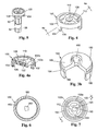
- the retainer 100 is a plastic part having a cylindrical body 102 with three flexible legs 104. Each of the legs 104 includes a clip fastener 106 to enable the retainer 100 to be snap fit about top of the cable anchor 90 (see Figs. 3 and 5).
- Figs. 4 and 4a show a magnet retainer that includes a center hub 108 having a bore 110 and plurality of webs 110 securing the hub to the outer wall of the body 102.
- a magnet 120 is not shown in Fig. 4 but is shown in Fig. 4a and is secured to the retainer 100 at the bore 110.
- the retainer 100 includes a web 122 at the bottom of bore 110 to provide a platform upon which the magnet can be fastened.
- the top 102b of the side wall 102a extends above the web 108 and the top of the magnet 120 and acts as a stop and defines a gap, g, with mating parts and also assists in setting the preload force of a bias spring.
- the retainer 100 locates the magnet relative to the end of the cable anchor 90.
- the magnet retainer can be integrally formed as part of end 124 of the anchor, such as by cold-forming a projecting boss, which would provide a platform that is similar in function to the web 122.
- the anchor 90 can be formed with a recess (see phantom line 126) into which the magnet can be placed. If the magnet retainer 100 is integrally formed at the end of the cable anchor 90, the length of the end 124 of the cable anchor would be appropriately lengthened (or the spring can be moved upwards making the sensor 50 smaller and lighter as well as eliminating two parts) such that the magnet is positioned at the location shown in Fig. 3.
- the sensor 50 additionally includes a cylindrical piston 140.
- the piston includes a step bore 142 that defines the preferred thickness of the walls of the piston.
- the piston stabilizes the cable anchor relative to the longitudinal axis of the sensor 50 and prevents the anchor 90 from cocking, which would add friction and also improperly move the magnet relative to a magnetic sensor.
- the upper cylindrical wall 144a envelops the sides of the flange 94 to further stabilize the anchor.
- An intermediate wall 144b provides a step below the underside of the flange and reduces the size of the bore 142 such that it is closely spaced relative to the body 92 of the cable anchor 90 providing added support.
- the lower wall 144c is of the largest diameter and defines a spring-receiving cavity 146 for a compression spring 148.
- the spring 148 resists this motion and urges the piston 140 and hence the cable anchor 90 upwardly.
- the bottom 145 of the piston will act as a stop if the force sensor 50 (50') is subjected to very high separating forces such as may occur during the operation of the pretensioner 52.
- the sensor 50 additionally includes a cap (or buckle anchor) 150 that is secured to the housing 70.
- the cap 150 is hollow and has threads 152, which mate with threads 154 formed on the housing 70.
- the cap 150 functions as a buckle anchor and includes a fastener or anchor 154 that is adapted to be secured, either directly or indirectly, such as through a cable (see phantom line 156 in Fig. 2), or a length of seat belt webbing to the buckle 36 or a rivet (not shown).
- the walls 160 of the cap also define a cavity 162.
- a sensor retainer 180 Fixedly positioned relative to the cap is a sensor retainer 180.
- Fig. 3b shows a partial cross-sectional view of the sensor retainer.
- the sensor retainer has a cylindrical body 182 with a cylindrical flange or sleeve 184 that is received within a cylindrical groove 186 formed on an interior wall of the cap 150.
- the sleeve or flange 184, on an interior wall includes a circular projection 185, which is preferably semi-circular in cross-section to radially stabilize the piston relative to the axis of the sensor 50.
- the shape of the projection 185 provides a point contact, further reducing friction.
- the projection can also be flat but preferably of a short dimension to keep friction low.
- the sensor retainer is sandwiched between the housing 70 and the cap 150.
- the top 188 of the sensor retainer includes a groove, passage, or bore 190 into which a magnetic sensor 200 is received.
- the magnetic sensor can be, for example, a Hall effect or variable reluctance sensor, or a magneto-restrictive sensor which provides a signal, the level of which varies in relationship to the relative distance between it (the magnetic sensor) and the magnet 120.
- Wires, such as 202, emanating from the sensor 200 can be communicated out from the force sensor 50 through an opening 204 in the cap.
- the wires are in circuit communication with conditioning electronics or directly with a microprocessor.
- Sensors of the variety mentioned above can provide a variable signal indicative of the variable distance between the magnet 120 and the sensor or, alternatively, provide a digital output (on or off) indicative that a certain separation distance has been achieved as the force sensor 50 is loaded.
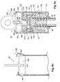
- Figs. 8a and 8b show an alternate force sensor 50' that utilizes many of the components previously described in relationship to Figs. 2 and 3.
- the housing 70' of this force sensor is considerably longer than the housing 70 of Fig. 2. Additionally, the threaded connection between housing 70 and connector 150 has been removed.
- the housing 70' includes a plurality of openings 300 disposed about its periphery near an upper end thereof.
- the walls 302 of the cap 150 include a plurality of engagement features 304, such as a triangularly shaped projection. The cap 150 is pushed within housing 70' such that the features 304 are received and locked within openings 300.
- Fig. 8a also shows a similar variant with regard to how to secure the sensor retainer 150 in place.
- the sensor retainer 180' of Fig. 8a also includes a plurality of projections 310, each of which is received within a corresponding opening 312, also formed within the wall of housing 70'.
- the cable retainer can include provision to hold and retain the magnet 120.
- the cable retainer 90" includes a bore 110 to receive the magnet.
- the top of the cable retainer 90" is formed in the shape of the top of the magnet retainer and includes an integrally formed, preferably annular wall 102a, which spaces the magnet properly relative to the sensor retainer 180".
- the housing 70" and the sensor retainer 180" do not include the openings 312 and projections 310 shown in Fig. 8a, which were used to hold the sensor retainer in place in the housing 70'.
- housing 70" is formed with an annular groove 320, which receives the complementary-shaped lower surface 322 of the cylindrical flange or sleeve 184.
- the housing 70' further includes an annular groove 324 with a cylindrical side wall 324 and an inner wall 328, which is angled upwardly to give the groove a sharp notch or V-like shape.
- the lower surface 340 includes an angled, peripheral wall 342 that is shaped to matingly engage with the inner wall 328.
- the reaction forces are directed inwardly, which prevents the housing from buckling.
- the number of parts in this embodiment has been lowered, which should result in a lower cost and with the removal of the piston, the diameter of the sensor 50" can be made smaller than the earlier embodiments.
- Figs. 9-11 show a further embodiment of a force sensor 50a.
- Fig. 10 shows the null position of the sensor and
- Fig. 11 shows the active state of the sensor with the magnet moved a distance, d, relative to the stationary sensor.
- the force sensor 50a includes a housing 70a having two parts 71a, 71b, which clamp together or fit together in a clam shell manner.
- Each of the housing parts 70a, 70b is preferably formed as a metal stamping, forging or casting.
- the housings include two upraised bridge portions 400, 402. When the housing parts are mated together, the opposed bridge sections 400, 402 provide a passageway for various moveable parts.
- Each of the housing portions includes a plurality of openings 404, which can be secured together by rivets 406 or other fastening mechanisms including welding.
- An end 55 of cable 54 is secured to a cable retainer 90a.
- the cable retainer is formed as a square annulus.
- the bottom 410 of the retainer is wider than the diameter of the cable 54.
- the portions 412a, 412b that extend outwardly from the cable function as a stop.
- the magnet 120 is received within a magnet retainer 100a, which includes flexible legs 104 that are clipped about the top or far end 414 of the cable retainer.
- This force sensor 50a includes a sensor retainer 180a into which a magnetic sensor 200 is received.
- the sensor retainer 180 includes a plurality of integrally formed bosses 419, which are received within openings 422 formed in each of the bridges 402 of the housing parts 71a, 71b.
- the cable 54 is received within a hollow sleeve, which functions as a bushing 86a.
- the bushing or sleeve 86a includes a flange 420. When in position, the flange 420 rests against the flange or stops 412a and 412b of the cable retainer.
- a spring 148 is fit about the bushing 86a and biases the cable anchor 90a into the housing 70a and resists the outward pulling motion of the cable 54.
- Each housing part 71a, 71b includes a pair of steps 430, which are sized to receive the extending portions 412a, 412b of the anchor 90a and, in combination with these portions, act as a stop (see Fig. 9) to prevent excessive outward motion of the cable.
- the top bridge 400 in Figs. 10 and 11 has been removed to show opposing walls 440 that guide the cable retainer 90a as it slides back and forth.
- the sensor retainer and sensor are also shown in cross-section in these Figs..
- Fig. 12 shows a further embodiment of the sensor retainer 180a.
- the sensor retainer includes a pair of opposing wings 442.
- Each wing includes a crosspiece 444, which extends perpendicularly relative to the wing.
- Each crosspiece lies adjacent a corresponding side of the cable retainer 90a and provides a low friction interface with the walls 440 of the frame.
- the crosspieces 442 are made of a material that is dissimilar to the frame.
- the entire sensor retainer, including the crosspieces is preferably plastic.
- Fig. 13 shows still another variant of the invention and is very similar to the embodiment of Fig. 9.
- the cable retainer 90a includes two notches 450 at its far end 414.
- the magnet retainer 100b is received against end 414 as in the earlier embodiment.
- the retainer 100b includes a pair of lower wings 452, which are positioned on the undersurface of the sides of the cable retainer and a pair of upper wings 452 rest on the top surface of the cable retainer.
- the magnet retainer 100b is further secured to the cable retainer 90a with depending legs 256, which snap into a corresponding notch 250.
- the legs slide against the frame walls 440 to provide a low-friction interface.
- the legs 256 in combination with the sleeve or bushing 86a, provide a three-point mounting to prevent the cable retainer from cocking as it moves.
Landscapes
- Engineering & Computer Science (AREA)
- Physics & Mathematics (AREA)
- General Physics & Mathematics (AREA)
- Mechanical Engineering (AREA)
- Chemical & Material Sciences (AREA)
- Analytical Chemistry (AREA)
- Textile Engineering (AREA)
- Automation & Control Theory (AREA)
- Force Measurement Appropriate To Specific Purposes (AREA)
- Automotive Seat Belt Assembly (AREA)
- Measurement Of Length, Angles, Or The Like Using Electric Or Magnetic Means (AREA)
Claims (10)
- Kraftsensor (50, 50', 50a) zum Erzeugen eines Signals, das die Benutzung eines Sicherheitsgurts anzeigt, wobei der Sensor folgendes umfaßt:ein zylindrisches Gehäuse (70, 70'), das eine Wand (72) und einen Boden (74) hat, wobei der Boden eine Öffnung (76) in demselben hat, wobei das Gehäuse einen inneren Hohlraum (124) definiert,einen Kabelanker (90), verschiebbar innerhalb des Hohlraums aufgenommen und geeignet, mit einem Kabel (54) verbunden zu sein, wobei das Kabel ein an dem Kabelanker befestigtes Ende und ein anderes, wirksam mit einem Ankerpunkt verbundenes, Ende hat,einen Magneten (120), verbunden mit einem Oberteil des Kabelankers und beweglich mit dem Kabelanker,ein Mittel zum Vorspannen des Kabelankers, um einer Bewegung des Kabelankers zum Boden des Gehäuses hin zu widerstehen,einen Magnetsensor (200) zum Erzeugen eines Signals, das die Entfernung zwischen ihm und dem Magneten anzeigt, wobei eine solche Entfernung proportional zu einer auf den Sicherheitsgurt ausgeübten Kraft ist,ein Sensorgehäuse (180), verbunden mit dem Gehäuse und auf dem Gehäuse angeordnet, um den Sensor in einer bestimmbaren Entfernung von dem Magneten an einer Nullposition anzuordnen,eine Gehäuseendkappe (150), befestigt an dem Gehäuse, um ein offenes Ende des Gehäuses zu umschließen, wobei der Magnet und das Sensormittel im Verhältnis zueinander bewegt werden können, wenn eine Kraft eines bestimmbaren Niveaus auf die Endkappe ausgeübt wird, wodurch die relative Bewegung des Magneten und des Sensors verursacht wird.
- Kraftsensor nach Anspruch 1, wobei das Mittel zum Vorspannen des Kabelankers einen hohlen, zylindrischen Kolben (140) innerhalb des Gehäusehohlraums (124) und eine Feder (148) zwischen dem Kolben und dem Gehäuse einschließt.
- Kraftsensor nach Anspruch 1, wobei ein Oberteil des Kabelankers einen Flansch (94) einschließt und der Kolben (140) einen passenden Wandabschnitt (144a, 144b) einschließt, um den Kabelanker verschiebbar aufzunehmen und den Kabelanker im Verhältnis zu einer Mittelachse des Gehäuses zu stabilisieren.
- Kraftsensor nach Anspruch 2, der ferner eine reibungsarme ringförmige Führung einschließt, die mit einer äußeren Wand des Kolbens zusammenwirkt, um den Kolben im Verhältnis zu einer Mittelachse des Gehäuses zu stabilisieren.
- Kraftsensor nach Anspruch 1, der ferner einen Magnethalter (100) zum Festhalten des Magneten am Kabelanker umfaßt.
- Kraftsensor nach Anspruch 5, wobei der Magnethalter (100) nichtmagnetisch ist.
- Kraftsensor nach Anspruch 6, wobei der Magnethalter (122) integral als ein Teil des Kabelankers geformt ist.
- Kraftsensor nach Anspruch 4, wobei die ringförmige Führung integral als ein Teil des Sensorgehäuses geformt ist.
- Kraftsensor nach Anspruch 1, wobei der Kabelanker und das Gehäuse Kraftmittel einschließen, um einer Auswärtsverformung des Gehäuses zu widerstehen.
- Kraftsensor nach Anspruch 1, wobei das Sensorgehäuse entweder an der Endkappe oder dem Gehäuse befestigt ist.
Applications Claiming Priority (5)
| Application Number | Priority Date | Filing Date | Title |
|---|---|---|---|
| US20216200P | 2000-05-04 | 2000-05-04 | |
| US202162P | 2000-05-04 | ||
| US09/597,042 US6400145B1 (en) | 2000-05-04 | 2000-06-20 | Seat belt tension sensor, methods of integration and attachment |
| US597042 | 2000-06-20 | ||
| PCT/US2001/012743 WO2001083275A2 (en) | 2000-05-04 | 2001-04-19 | Seat belt tension sensor |
Publications (2)
| Publication Number | Publication Date |
|---|---|
| EP1278663A2 EP1278663A2 (de) | 2003-01-29 |
| EP1278663B1 true EP1278663B1 (de) | 2005-12-28 |
Family
ID=26897412
Family Applications (1)
| Application Number | Title | Priority Date | Filing Date |
|---|---|---|---|
| EP01928655A Expired - Lifetime EP1278663B1 (de) | 2000-05-04 | 2001-04-19 | Sicherheitsgurtspannungssensor |
Country Status (6)
| Country | Link |
|---|---|
| US (2) | US6400145B1 (de) |
| EP (1) | EP1278663B1 (de) |
| AU (1) | AU2001255489A1 (de) |
| DE (1) | DE60116283T2 (de) |
| ES (1) | ES2254407T3 (de) |
| WO (1) | WO2001083275A2 (de) |
Families Citing this family (73)
| Publication number | Priority date | Publication date | Assignee | Title |
|---|---|---|---|---|
| US6820458B2 (en) * | 2000-05-04 | 2004-11-23 | Key Safety Systems, Inc. | Seat belt force sensor |
| JP2003533399A (ja) * | 2000-05-12 | 2003-11-11 | シーメンス ヴィディーオー オートモーティヴ コーポレイション | シートベルトにかかる力のセンサー装置 |
| US20030070846A1 (en) * | 2001-03-26 | 2003-04-17 | Trw Inc. | Parallelogram load sensing apparatus for a seat belt webbing |
| US7272979B2 (en) * | 2001-06-19 | 2007-09-25 | Cts Corporation | Seat belt tension sensor having an integral connector |
| US7263906B2 (en) * | 2001-06-19 | 2007-09-04 | Cts Corporation | Seat belt tension sensor |
| US7347108B2 (en) * | 2001-06-19 | 2008-03-25 | Cts Corporation | Seat belt tension sensor |
| US7086297B2 (en) * | 2001-08-06 | 2006-08-08 | Cts Corporation | Seat belt tension sensor having shock isolation |
| US6578432B2 (en) * | 2001-06-19 | 2003-06-17 | Cts Corporation | Seat belt tension sensor |
| US7373845B2 (en) * | 2001-06-19 | 2008-05-20 | Cts Corporation | Seat belt tension sensor |
| US6776056B2 (en) * | 2001-08-06 | 2004-08-17 | Cts Corporation | Seat belt tension sensor |
| US20030066362A1 (en) * | 2001-08-29 | 2003-04-10 | Lee Shih Yuan | Seat belt tension sensor |
| US6679524B2 (en) * | 2001-11-14 | 2004-01-20 | Delphi Technologies, Inc. | Tension sensing assembly |
| US6796192B2 (en) | 2001-12-19 | 2004-09-28 | Delphi Technologies, Inc. | Pass through seat restraint tension sensing assembly |
| US6829952B2 (en) | 2002-02-13 | 2004-12-14 | Automotive Systems Laboratory, Inc. | Seat belt tension sensor |
| US6851715B2 (en) * | 2002-03-12 | 2005-02-08 | Trw Vehicle Safety Systems Inc. | Apparatus for measuring tension in seat belt webbing |
| DE10217227C1 (de) * | 2002-04-18 | 2003-05-22 | Autoliv Dev | Für eine Gurtkraftmessung eingerichtete Befestigungsanordnung für ein Sicherheitsgurtschloß |
| US6868745B2 (en) * | 2002-05-07 | 2005-03-22 | Delphi Technologies, Inc. | Seat restraint buckle and tension sensing assembly |
| US6957829B2 (en) * | 2002-05-10 | 2005-10-25 | Delphi Technologies, Inc. | Tension sensing assembly |
| AU2003237468A1 (en) * | 2002-06-07 | 2003-12-22 | Automotive Systems Laboratory, Inc. | Seat belt tension sensor |
| CN1682099A (zh) * | 2002-07-10 | 2005-10-12 | 汽车系统实验室公司 | 将座椅安全带连接座椅安全带张力传感器上的方法 |
| RO120766B1 (ro) * | 2002-07-16 | 2006-07-28 | Siemens Aktiengesellschaft | Element dinamometric pentru măsurarea forţei de tracţiune din centura care acţionează asupra broaştei centurii |
| RO120896B1 (ro) * | 2002-07-16 | 2006-09-29 | Siemens Aktiengesellschaft | Carcasă pentru broasca de centură, cu dispozitiv dinamometric integrat |
| DE60204311T2 (de) * | 2002-09-02 | 2006-01-26 | Key Safety Systems, Inc., Sterling Heights | Einstellvorrichtung und -verfahren für eine Kalibrierfeder |
| US6978687B2 (en) | 2003-01-17 | 2005-12-27 | Stoneridge Control Devices, Inc. | Seat belt tension sensor |
| US6894485B2 (en) * | 2003-02-10 | 2005-05-17 | Delphi Technologies, Inc. | Position sensing by measuring intensity of magnetic flux passing through an aperture in a movable element |
| US6997478B2 (en) * | 2003-03-14 | 2006-02-14 | Delphi Technologies, Inc. | Tension sensing assembly |
| US20040256877A1 (en) * | 2003-04-08 | 2004-12-23 | Tromblee Gerald Alan | Child safety seat sensor system and method |
| EP1468881B1 (de) * | 2003-04-14 | 2005-12-21 | Ford Global Technologies, LLC | Eine Sicherheitsgurtvorrichtung |
| US7347452B2 (en) * | 2003-04-23 | 2008-03-25 | Delphi Technologies, Inc. | Tension sensing assembly |
| US6952974B2 (en) * | 2003-06-12 | 2005-10-11 | Delphi Technologies, Inc. | Seat belt tension sensor |
| US6903286B2 (en) * | 2003-06-25 | 2005-06-07 | Cts Corporation | Tension sensing device |
| EP1498323B1 (de) * | 2003-07-17 | 2007-08-22 | Key Safety Systems, Inc. | Befestigungsvorrichtung für ein Sicherheitsgurtschloss |
| US7242286B2 (en) * | 2003-08-22 | 2007-07-10 | Autoliv Asp, Inc. | Seat belt tension indicator |
| US7566271B2 (en) * | 2003-09-10 | 2009-07-28 | Igt | Gaming device having a selection game with multiple groups of potential outcomes |
| ITTO20040007A1 (it) * | 2004-01-09 | 2004-04-09 | Lupa Kid S R L | Dispositivo di segnalazione del corretto tensionamento di un nastro di ritenuta di un dispositivo di sicurezza. |
| US7383744B2 (en) * | 2005-02-18 | 2008-06-10 | Stoneridge Control Devices, Inc. | Seat belt tension sensor |
| US7454979B2 (en) * | 2005-05-20 | 2008-11-25 | Stoneridge Control Devices, Inc. | Linear position sensor |
| US7263750B2 (en) | 2005-06-09 | 2007-09-04 | Amsafe, Inc. | Buckle assembly having single release for multiple belt connectors |
| US8132864B2 (en) * | 2006-07-20 | 2012-03-13 | Blackmon Michael M | Child safety seat with emergency harness release |
| JP5085229B2 (ja) * | 2007-08-22 | 2012-11-28 | Ntn株式会社 | 乗員重量検出装置 |
| US20090069983A1 (en) * | 2007-09-10 | 2009-03-12 | Todd Humbert | Occupant restraint systems for use in military land vehicles and other vehicles |
| WO2009091843A1 (en) * | 2008-01-14 | 2009-07-23 | University Of Alabama | Systems and methods for releasing children from safety seats |
| US8646158B2 (en) | 2008-03-31 | 2014-02-11 | Amsafe Commercial Products, Inc. | Multi-pivot latch assemblies |
| US8713765B2 (en) | 2008-03-31 | 2014-05-06 | Amsafe Commercial Products, Inc. | Multi-pivot latch assemblies |
| US7918001B2 (en) * | 2008-03-31 | 2011-04-05 | Amsafe Commercial Products, Inc. | Multi-pivot latch assemblies |
| US8291555B2 (en) | 2008-03-31 | 2012-10-23 | Amsafe Commercial Products, Inc. | Multi-pivot latch assemblies |
| WO2010037103A1 (en) | 2008-09-29 | 2010-04-01 | Amsafe, Inc. | Tensioning apparatuses for occupant restraint systems and associated systems and methods |
| US8469401B2 (en) | 2009-02-23 | 2013-06-25 | Amsafe, Inc. | Seat harness pretensioner |
| US8403612B2 (en) * | 2009-07-29 | 2013-03-26 | Toyota Motor Engineering & Manufacturing North America, Inc. | Fastener assembly |
| US8393645B2 (en) | 2009-11-02 | 2013-03-12 | Amsafe Commercial Products, Inc. | Devices for adjusting tension in seat belts and other restraint system webs, and associated methods |
| US8683666B2 (en) | 2009-11-04 | 2014-04-01 | Amsafe Commercial Products, Inc. | Restraint system buckle components having tactile surfaces, and associated methods of use and manufacture |
| US8627554B1 (en) | 2010-05-03 | 2014-01-14 | Amsafe, Inc. (Phoenix Group) | Buckle assemblies with swivel and dual release features and associated methods of use and manufacture |
| US8365874B2 (en) * | 2010-06-21 | 2013-02-05 | Automotive Research & Testing Center | Electric parking brake actuator |
| US8777323B2 (en) | 2010-07-20 | 2014-07-15 | Amsafe, Inc. | Restraint harnesses and associated methods of use and manufacture |
| USD661619S1 (en) | 2010-09-15 | 2012-06-12 | Amsafe Commercial Products, Inc. | Buckle assembly |
| USD655223S1 (en) | 2010-09-15 | 2012-03-06 | Amsafe Commercial Products, Inc. | Buckle assembly |
| US9022483B2 (en) | 2012-06-07 | 2015-05-05 | Shield Restraint Systems, Inc. | Seatbelt buckle tongue assembly |
| EP2958453A4 (de) | 2013-02-19 | 2016-07-27 | Amsafe Inc | Schnallenanordnungen mit hebeverschlüssen und zugehörige verfahren und systeme |
| US9277788B2 (en) | 2013-02-19 | 2016-03-08 | Amsafe, Inc. | Dual release buckle assemblies and associated systems and methods |
| US9718427B2 (en) | 2013-07-19 | 2017-08-01 | Shield Restraint Sytems, Inc. | Latch device and anchor with swivel coupling |
| CH708643A2 (de) * | 2013-09-25 | 2015-03-31 | Polycontact Ag | Gurtschloss mit Hallsensor. |
| US9358914B2 (en) | 2014-06-05 | 2016-06-07 | Amsafe, Inc. | Seatbelt anchor systems for aircraft and other vehicles, and associated methods of manufacture and use |
| WO2016100566A1 (en) | 2014-12-16 | 2016-06-23 | Shield Restraint Systems, Inc. | Web adjusters for use with restraint systems and associated methods of use and manufacture |
| US11815352B2 (en) | 2015-02-17 | 2023-11-14 | Schlumberger Technology Corporation | Apparatus and method for determining borehole size with a borehole imaging tool |
| US20160237809A1 (en) * | 2015-02-17 | 2016-08-18 | Schlumberger Technology Corporation | Downhole Tool Non Contact Position Measurement System |
| US10604259B2 (en) | 2016-01-20 | 2020-03-31 | Amsafe, Inc. | Occupant restraint systems having extending restraints, and associated systems and methods |
| US9814282B2 (en) | 2016-02-02 | 2017-11-14 | Shield Restraint Systems, Inc. | Harsh environment buckle assemblies and associated systems and methods |
| DE112017000786T5 (de) | 2016-02-11 | 2018-11-15 | Joyson Safety Systems Acquisition Llc | Sitzgurt- und kindersitzankerbasiertes Belegungsdetektionssystem |
| US9802512B1 (en) | 2016-04-12 | 2017-10-31 | Ford Global Technologies, Llc | Torsion spring bushing |
| US10611334B2 (en) | 2017-02-07 | 2020-04-07 | Shield Restraint Systems, Inc. | Web adjuster |
| US10252640B2 (en) | 2017-08-21 | 2019-04-09 | Joyson Safety Systems Acquisition Llc | Seatbelt and child seat anchor based occupancy detection system |
| US20200079316A1 (en) * | 2018-09-11 | 2020-03-12 | GM Global Technology Operations LLC | Safety restraint system and method |
| WO2024245547A1 (en) * | 2023-05-31 | 2024-12-05 | Zf Automotive Germany Gmbh | Fastener and connector system for connecting a seat belt system with an anchor |
Family Cites Families (9)
| Publication number | Priority date | Publication date | Assignee | Title |
|---|---|---|---|---|
| US4654643A (en) * | 1985-07-22 | 1987-03-31 | Meisenheimer Jr Daniel T | Pressure sensor-monitor and excessive pressure level indicator |
| JPH02227348A (ja) * | 1989-03-01 | 1990-09-10 | Nippon Seiko Kk | 車両乗員保護装置用マグネット組込部品 |
| US6336371B1 (en) * | 1997-01-09 | 2002-01-08 | Automotive Systems Laboratory, Inc. | Villari effect seatbelt tension sensor |
| WO1999012012A1 (en) * | 1997-09-04 | 1999-03-11 | Breed Automotive Technology, Inc. | Apparatus to measure seat belt tension |
| US6205868B1 (en) * | 1997-12-10 | 2001-03-27 | Automotive Systems Lab | Hall-effect seat belt tension sensor |
| US6079744A (en) | 1998-04-24 | 2000-06-27 | Breed Automotive Technology, Inc. | Device to detect seat belt buckle status |
| US5996421A (en) | 1998-04-24 | 1999-12-07 | Breed Automotive Technology, Inc. | Seat belt tension sensor employing flexible potentiometer |
| US6081759A (en) | 1998-04-24 | 2000-06-27 | Breed Automotive Technology, Inc. | Seat belt tension sensor |
| US5960523A (en) * | 1998-08-25 | 1999-10-05 | Breed Automotive Technology, Inc. | Seat belt buckle sensor |
-
2000
- 2000-06-20 US US09/597,042 patent/US6400145B1/en not_active Expired - Lifetime
-
2001
- 2001-04-19 AU AU2001255489A patent/AU2001255489A1/en not_active Abandoned
- 2001-04-19 ES ES01928655T patent/ES2254407T3/es not_active Expired - Lifetime
- 2001-04-19 DE DE60116283T patent/DE60116283T2/de not_active Expired - Fee Related
- 2001-04-19 WO PCT/US2001/012743 patent/WO2001083275A2/en not_active Ceased
- 2001-04-19 EP EP01928655A patent/EP1278663B1/de not_active Expired - Lifetime
-
2002
- 2002-06-04 US US10/161,926 patent/US6566869B2/en not_active Expired - Fee Related
Also Published As
| Publication number | Publication date |
|---|---|
| US6400145B1 (en) | 2002-06-04 |
| WO2001083275A3 (en) | 2002-06-13 |
| DE60116283T2 (de) | 2006-08-31 |
| US20020145422A1 (en) | 2002-10-10 |
| US6566869B2 (en) | 2003-05-20 |
| WO2001083275A2 (en) | 2001-11-08 |
| AU2001255489A1 (en) | 2001-11-12 |
| ES2254407T3 (es) | 2006-06-16 |
| DE60116283D1 (de) | 2006-02-02 |
| EP1278663A2 (de) | 2003-01-29 |
Similar Documents
| Publication | Publication Date | Title |
|---|---|---|
| EP1278663B1 (de) | Sicherheitsgurtspannungssensor | |
| JP4138652B2 (ja) | シートベルトプリテンショナ装置 | |
| CN100579834C (zh) | 预张紧器和安全带装置 | |
| EP1272376B1 (de) | Fühler für sicherheitsgurtspannung | |
| US7404239B1 (en) | Adjuster for adjustable restraint strap | |
| EP0561274A1 (de) | Sicherheitsgurtsystem mit Mitteln zum Vermeiden eines zu engen Gurtsitzes und der durch diesen erzeugten Reibung | |
| EP1930209A1 (de) | Insassenmessvorrichtung für fahrzeugsitz und installationsstruktur für lastsensor | |
| EP1997670A2 (de) | Kindersitzverankerungsvorrichtung und Kindersitz | |
| US6851715B2 (en) | Apparatus for measuring tension in seat belt webbing | |
| EP0289628B1 (de) | Verankerungsanordnung für sitzgurte | |
| US20040135360A1 (en) | Method of attaching a seat belt to a seat belt tension sensor | |
| US5725249A (en) | Preloader apparatus | |
| US9004531B1 (en) | Releasable tether retention system | |
| EP0290621B1 (de) | Verankerungsanordnung für sicherheitsgurte | |
| US20040245761A1 (en) | Tension sensing assembly | |
| US6851714B2 (en) | Seat belt closure-securement arrangement with integrated force evaluation | |
| KR102093797B1 (ko) | 시트벨트 가이드 루프 높이 조절 장치 | |
| US6957829B2 (en) | Tension sensing assembly | |
| US5924730A (en) | Pretensioning buckle | |
| US8960723B2 (en) | Quick-release closure for a vehicle-fixed end of a seat belt in a motor vehicle | |
| US7258189B2 (en) | Seat belt apparatus | |
| US6016589A (en) | Buckle for a safety belt | |
| KR100353911B1 (ko) | 자동차용 버클의 높이조절장치 | |
| WO2026063365A1 (ja) | 分離タング及びシートベルト装置 | |
| JPH0716522Y2 (ja) | オートマチツクシートベルト装置 |
Legal Events
| Date | Code | Title | Description |
|---|---|---|---|
| PUAI | Public reference made under article 153(3) epc to a published international application that has entered the european phase |
Free format text: ORIGINAL CODE: 0009012 |
|
| 17P | Request for examination filed |
Effective date: 20020925 |
|
| AK | Designated contracting states |
Designated state(s): AT BE CH CY DE DK ES FI FR GB GR IE IT LI LU MC NL PT SE TR |
|
| RBV | Designated contracting states (corrected) |
Designated state(s): AT BE CH CY DE ES FR GB IT LI |
|
| GRAP | Despatch of communication of intention to grant a patent |
Free format text: ORIGINAL CODE: EPIDOSNIGR1 |
|
| GRAS | Grant fee paid |
Free format text: ORIGINAL CODE: EPIDOSNIGR3 |
|
| RAP1 | Party data changed (applicant data changed or rights of an application transferred) |
Owner name: KEY SAFETY SYSTEMS, INC. |
|
| GRAA | (expected) grant |
Free format text: ORIGINAL CODE: 0009210 |
|
| AK | Designated contracting states |
Kind code of ref document: B1 Designated state(s): DE ES FR GB IT |
|
| RBV | Designated contracting states (corrected) |
Designated state(s): DE ES FR GB IT |
|
| REG | Reference to a national code |
Ref country code: GB Ref legal event code: FG4D |
|
| REF | Corresponds to: |
Ref document number: 60116283 Country of ref document: DE Date of ref document: 20060202 Kind code of ref document: P |
|
| PGFP | Annual fee paid to national office [announced via postgrant information from national office to epo] |
Ref country code: GB Payment date: 20060314 Year of fee payment: 6 |
|
| PGFP | Annual fee paid to national office [announced via postgrant information from national office to epo] |
Ref country code: FR Payment date: 20060403 Year of fee payment: 6 |
|
| PGFP | Annual fee paid to national office [announced via postgrant information from national office to epo] |
Ref country code: ES Payment date: 20060424 Year of fee payment: 6 |
|
| PGFP | Annual fee paid to national office [announced via postgrant information from national office to epo] |
Ref country code: DE Payment date: 20060428 Year of fee payment: 6 |
|
| REG | Reference to a national code |
Ref country code: ES Ref legal event code: FG2A Ref document number: 2254407 Country of ref document: ES Kind code of ref document: T3 |
|
| ET | Fr: translation filed | ||
| PLBE | No opposition filed within time limit |
Free format text: ORIGINAL CODE: 0009261 |
|
| STAA | Information on the status of an ep patent application or granted ep patent |
Free format text: STATUS: NO OPPOSITION FILED WITHIN TIME LIMIT |
|
| 26N | No opposition filed |
Effective date: 20060929 |
|
| GBPC | Gb: european patent ceased through non-payment of renewal fee |
Effective date: 20070419 |
|
| PG25 | Lapsed in a contracting state [announced via postgrant information from national office to epo] |
Ref country code: DE Free format text: LAPSE BECAUSE OF NON-PAYMENT OF DUE FEES Effective date: 20071101 |
|
| PG25 | Lapsed in a contracting state [announced via postgrant information from national office to epo] |
Ref country code: GB Free format text: LAPSE BECAUSE OF NON-PAYMENT OF DUE FEES Effective date: 20070419 |
|
| REG | Reference to a national code |
Ref country code: ES Ref legal event code: FD2A Effective date: 20070420 |
|
| PG25 | Lapsed in a contracting state [announced via postgrant information from national office to epo] |
Ref country code: FR Free format text: LAPSE BECAUSE OF NON-PAYMENT OF DUE FEES Effective date: 20070430 |
|
| PGFP | Annual fee paid to national office [announced via postgrant information from national office to epo] |
Ref country code: IT Payment date: 20080418 Year of fee payment: 8 |
|
| PG25 | Lapsed in a contracting state [announced via postgrant information from national office to epo] |
Ref country code: ES Free format text: LAPSE BECAUSE OF NON-PAYMENT OF DUE FEES Effective date: 20070420 |
|
| PG25 | Lapsed in a contracting state [announced via postgrant information from national office to epo] |
Ref country code: IT Free format text: LAPSE BECAUSE OF NON-PAYMENT OF DUE FEES Effective date: 20090419 |