EP1279437B1 - Verfahren zum Dosieren von Flüssigkeiten und Vorrichtung zur Durchführung des Verfahrens - Google Patents
Verfahren zum Dosieren von Flüssigkeiten und Vorrichtung zur Durchführung des Verfahrens Download PDFInfo
- Publication number
- EP1279437B1 EP1279437B1 EP02015813A EP02015813A EP1279437B1 EP 1279437 B1 EP1279437 B1 EP 1279437B1 EP 02015813 A EP02015813 A EP 02015813A EP 02015813 A EP02015813 A EP 02015813A EP 1279437 B1 EP1279437 B1 EP 1279437B1
- Authority
- EP
- European Patent Office
- Prior art keywords
- chamber
- volume
- liquid
- negative pressure
- reception
- Prior art date
- Legal status (The legal status is an assumption and is not a legal conclusion. Google has not performed a legal analysis and makes no representation as to the accuracy of the status listed.)
- Expired - Lifetime
Links
- 239000007788 liquid Substances 0.000 title claims abstract description 65
- 238000000034 method Methods 0.000 title claims abstract description 28
- 230000001105 regulatory effect Effects 0.000 claims abstract 2
- 238000006073 displacement reaction Methods 0.000 claims description 41
- 230000001276 controlling effect Effects 0.000 claims 2
- 230000008569 process Effects 0.000 abstract description 8
- 238000010586 diagram Methods 0.000 description 4
- TZCXTZWJZNENPQ-UHFFFAOYSA-L barium sulfate Chemical compound [Ba+2].[O-]S([O-])(=O)=O TZCXTZWJZNENPQ-UHFFFAOYSA-L 0.000 description 3
- 239000012530 fluid Substances 0.000 description 3
- 230000009471 action Effects 0.000 description 2
- 230000005484 gravity Effects 0.000 description 2
- 238000007654 immersion Methods 0.000 description 2
- 230000004044 response Effects 0.000 description 2
- 230000001133 acceleration Effects 0.000 description 1
- 230000005540 biological transmission Effects 0.000 description 1
- 230000008859 change Effects 0.000 description 1
- 238000006243 chemical reaction Methods 0.000 description 1
- 238000010276 construction Methods 0.000 description 1
- 230000008878 coupling Effects 0.000 description 1
- 238000010168 coupling process Methods 0.000 description 1
- 238000005859 coupling reaction Methods 0.000 description 1
- 230000000694 effects Effects 0.000 description 1
- 239000002245 particle Substances 0.000 description 1
- 230000001960 triggered effect Effects 0.000 description 1
- 238000009423 ventilation Methods 0.000 description 1
Images
Classifications
-
- G—PHYSICS
- G01—MEASURING; TESTING
- G01F—MEASURING VOLUME, VOLUME FLOW, MASS FLOW OR LIQUID LEVEL; METERING BY VOLUME
- G01F11/00—Apparatus requiring external operation adapted at each repeated and identical operation to measure and separate a predetermined volume of fluid or fluent solid material from a supply or container, without regard to weight, and to deliver it
- G01F11/28—Apparatus requiring external operation adapted at each repeated and identical operation to measure and separate a predetermined volume of fluid or fluent solid material from a supply or container, without regard to weight, and to deliver it with stationary measuring chambers having constant volume during measurement
-
- B—PERFORMING OPERATIONS; TRANSPORTING
- B01—PHYSICAL OR CHEMICAL PROCESSES OR APPARATUS IN GENERAL
- B01L—CHEMICAL OR PHYSICAL LABORATORY APPARATUS FOR GENERAL USE
- B01L3/00—Containers or dishes for laboratory use, e.g. laboratory glassware; Droppers
- B01L3/02—Burettes; Pipettes
- B01L3/021—Pipettes, i.e. with only one conduit for withdrawing and redistributing liquids
-
- G—PHYSICS
- G01—MEASURING; TESTING
- G01F—MEASURING VOLUME, VOLUME FLOW, MASS FLOW OR LIQUID LEVEL; METERING BY VOLUME
- G01F11/00—Apparatus requiring external operation adapted at each repeated and identical operation to measure and separate a predetermined volume of fluid or fluent solid material from a supply or container, without regard to weight, and to deliver it
- G01F11/02—Apparatus requiring external operation adapted at each repeated and identical operation to measure and separate a predetermined volume of fluid or fluent solid material from a supply or container, without regard to weight, and to deliver it with measuring chambers which expand or contract during measurement
- G01F11/021—Apparatus requiring external operation adapted at each repeated and identical operation to measure and separate a predetermined volume of fluid or fluent solid material from a supply or container, without regard to weight, and to deliver it with measuring chambers which expand or contract during measurement of the piston type
- G01F11/029—Apparatus requiring external operation adapted at each repeated and identical operation to measure and separate a predetermined volume of fluid or fluent solid material from a supply or container, without regard to weight, and to deliver it with measuring chambers which expand or contract during measurement of the piston type provided with electric controlling means
Definitions
- the invention relates to a method for dosing liquids and an apparatus for carrying out the method.
- the invention is based on the object, a method for dosing liquids and a device for dosing Create liquids with better handling properties.
- a chamber negative pressure is due to a predetermined target volume determined and generated in a chamber after immersion the opening into a liquid and connecting the receiving volume with the chamber has the consequence that exactly the desired volume in the receiving volume rises.
- the relationship between nominal volume and associated Chamber vacuum can be empirical, for example, for a liquid (in particular experimentally) can be determined.
- the gas present in the chamber is preferably air.
- the chamber vacuum can be generated in different ways. According to one embodiment the process becomes a negative pressure generated in the chamber measured and due to a comparison with the chamber vacuum on adapted to this.
- a negative pressure is initially generated in the chamber, which exceeds the chamber negative pressure and is then replaced by a partial Pressure equalization between chamber and environment of the chamber vacuum reached. In this way, the chamber vacuum can be particularly be generated easily and accurately.
- the negative pressure in the chamber automatically adjusted to the chamber vacuum.
- the liquid absorbed from the receiving volume be discharged to the outside, for example, if they are in the receiving volume or in a device having the receiving volume analyzed or further processed.
- the absorbed liquid according to an embodiment by applying an overpressure to the receiving volume expelled from the opening of the receiving volume.
- an overpressure can be a target volume of liquid from a reservoir in recorded in the recording volume and from the recording volume in a reaction vessel are dispensed.
- the nominal volume is entered manually. There a forced coupling to a transmission for the adjustment of a piston stop is omitted, the input of the target volume is very easy to use.
- the negative pressure and / or the overpressure generated by means of a manually operable gas displacement device This makes it possible, the process with very low equipment To carry out effort.
- the gas displacement device in Generating the negative pressure and / or the overpressure by a specific, actuated by the choice of the desired volume independent actuation. This is more manageable than the variable actuation paths in the known adjustable pipettes.
- an overstroke can ensure that the liquid practically completely expelled from the receiving volume becomes.
- the first and the second Valve device can be opened so that the gas escapes into the environment. It is also possible when displacing the gas from the gas displacement device the second valve means and a chamber with Open environment connecting third valve device.
- the first valve device and the possibly existing third valve means closed and opened the second valve device. Thereafter, by means of the gas displacement device Gas will be withdrawn from the chamber. This can a gradual increase in negative pressure causes the stopped when the pressure sensor detects the chamber vacuum. Then can the second valve means are closed.
- the control device controls the work of the valve devices in Dependence on the input by means of the input devices Information and the readings that the pressure sensor provides.
- the handheld pipette can be designed so that the operation is largely analogous to the operation of conventional hand-held pipettes.
- Another device suitable for carrying out the method distinguishes from the above in that the chamber does not have a second valve device is connected to the gas displacement device, but that the gas displacement means the chamber as a displacement chamber having.
- the control device is connected to the first valve device connected and optionally with a third valve device, which connects the chamber with the environment.
- gas can be displaced from the displacement chamber be, by the first valve means or the possibly existing third valve device is opened. After that, the first or the third valve means closed and the negative pressure in the displacement chamber generated.
- This process can be achieved by achieving the chamber vacuum be limited. Instead, it is possible to have a Chamber negative pressure exceeding negative pressure, regardless of the selected target volume is to generate and then by opening the first or the third valve device to adjust the chamber vacuum.
- the Working of the first and third valve device is performed by the control device controlled in accordance with the information provided by the Input devices are input and depending on the Measured values supplied by the pressure sensor. This device is special with low effort executable, since they are basically a single Valve device requires.
- the excluded from the receiving volume Liquid ejected by operating the gas displacement device become.
- the overpressure under opening the first and second valve means through the chamber in the receiving volume be initiated.
- the gas displacement device via a bypass with a fourth valve device directly with connected to the receiving volume and the controller with the fourth valve means connected to these for the delivery of liquid open when the gas displacement means an overpressure generated.
- the overpressure directly by opening the first valve means in the receiving volume be initiated.
- the input devices for the target volume a dial, with which the target volume is easily adjustable.
- the control wheel can have markings or symbols for the display of the set Have nominal volume.
- a separate display can be omitted.
- the Input devices may include a sensor for detecting actuation of the Gas displacement device to the intake or delivery of To control fluid in response to this operation.
- the gas displacement device is a piston-cylinder device or a bellows device.
- the gas displacement device can be performed similar to conventional pipettes be.
- the operation of the gas displacement device is preferably carried out manually. In principle, it can also be done by motor.
- the gas displacement device has a spring device for returning to a starting position.
- the gas displacement device must then be operated only in one direction. Preferably it is actuated to expel gas from the gas displacement device, as with conventional pipettes.
- the receiving volume is an exchangeable Pipette tip.
- Commercially available pipette tips can be used. Preferably, these are made of plastic.
- control direction and / or the Pressure sensor and / or the valve devices and / or the input devices electrical facilities is an electrical power supply for feeding at least one electrical device available.
- it is in the electrical power supply around at least one battery or at least one battery, in particular in a version as a handheld device.
- the device is a hand-held device.
- an embodiment provides that several parallel recording volumes are present to realize a multi-channel pipette.
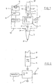
- the device has a chamber 1 for a gas.
- the chamber 1 is over a first valve device 2 connected to a replaceable pipette tip 3. This has below an opening 3 'to the environment.
- the Chamber 1 via a second valve device 4 with a piston-cylinder device 5 connected. This has a piston 5 ', the axially displaceable is arranged in a cylinder 5 ".
- the piston 5 ' is at the top with an actuating knob 5 '' 'connected.
- Via a third valve device 6 the chamber 1 is connected to the environment.
- a pressure sensor 7 is connected to the chamber 1.
- the pressure sensor 7 is connected to a computer 8 (e.g., a microcomputer).
- the computer 8 is also connected to the valve devices 2, 4 and 6.
- the elements 1, 2 and 4 to 9 are in a housing 10 accommodated. This has a seat 11 (e.g., plug-in cone) at the bottom the pipette tip 3 is seated with its upper opening 3 " 9 'and the actuating head 5' '' project from the top of the housing 10.
- a seat 11 e.g., plug-in cone
- the device works as follows:
- the integral is light solvable.
- the target volume V is intended to give the specific weight of the liquid and the geometric data of the pipette tip 3 known. This can be done by means of the input devices 9.
- the geometric data and specific gravity can also be stored.
- a selection can be made among stored values.
- valve devices 4 and 6 open, as shown in FIG. 1, air is forced out of the piston-cylinder device 5 by pushing down the piston 5 '. Subsequently, the valve means 6 is closed and the piston 5 'as shown in FIG. 2 moves upward, for example, by a piston return spring. In this case, the valve device 2 is closed and a negative pressure P 2 is generated in the chamber 1. This negative pressure P 2 is chosen so that it is greater than all chamber negative pressures P 1 in the adjustment range of the pipette. Thereafter, the valve device 4 is closed.
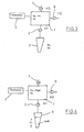
- the desired chamber pressure P 1 in the chamber 1 is set by the computer 8 by a controlled ventilation operation on the valve means 6 as shown in FIG.
- the pipette tip 3 can already be immersed in the liquid with the opening 3 '. The control process can take place so quickly that the user does not notice the delay of the fluid intake until the opening of the valve device 2.
- valve device 2 When the valve device 2 is open, the valve devices 4 and 6 remain closed.
- the flow rate of the valve device 2 may be selected so that the inflow velocity of the liquid corresponds to a discharge of the piston of a conventional hand-held pipette.
- the nominal volume V soll is received in the pipette tip 3 and the target negative pressure P soll is set in the pipette tip 3. This is shown in FIG. 4.
- the discharge of the liquid is effected after opening of the valve device 4 by downward movement of the piston 5 '.
- a particular overstroke is not required, since the displaced by the piston-cylinder device 5 air volume is anyway a larger than the target volume V soll .
- the operation of the device can analogously to the operation of conventional Piston stroke pipettes.
- the control of the valve devices 2, 4, 6 can from the computer 8 in response to the operation of the piston 5 ' be made.
- a sensor available be that detects the movement of the piston 5 'or a button that at every actuation of the actuating head 5 "is triggered.
Landscapes
- Physics & Mathematics (AREA)
- Fluid Mechanics (AREA)
- General Physics & Mathematics (AREA)
- Chemical Kinetics & Catalysis (AREA)
- Clinical Laboratory Science (AREA)
- Chemical & Material Sciences (AREA)
- Health & Medical Sciences (AREA)
- Feeding, Discharge, Calcimining, Fusing, And Gas-Generation Devices (AREA)
- Devices For Use In Laboratory Experiments (AREA)
- Sampling And Sample Adjustment (AREA)
- Processing And Handling Of Plastics And Other Materials For Molding In General (AREA)
- Casting Or Compression Moulding Of Plastics Or The Like (AREA)
- Measuring Fluid Pressure (AREA)
Description
- wird ein Sollvolumen der von dem Aufnahmevolumen aufzunehmenden Flüssigkeit vorgegeben,
- wird ein Kammerunterdruck ermittelt, der in der Kammer vorhanden sein muß, um nach Eintauchen der Öffnung in die Flüssigkeit und Verbinden der Kammer mit dem Aufnahmevolumen die Aufnahme des Sollvolumens der Flüssigkeit in dem Aufnahmevolumen zu bewirken,
- wird in der Kammer der Kammerunterdruck erzeugt,
- wird das Aufnahmevolumen mit der Öffnung in die Flüssigkeit eingetaucht und
- wird die Kammer mit dem Aufnahmevolumen verbunden und das Sollvolumen der Flüssigkeit in dem Aufnahmevolumen aufgenommen.
- eine Kammer für ein Gas,
- ein mit der Kammer über eine erste Ventileinrichtung verbundenes Aufnahmevolumen für eine Flüssigkeit mit einer Öffnung zur Umgebung,
- eine mit der Kammer über eine zweite Ventileinrichtung verbundene Gasverdrängungseinrichtung,
- einen an die Kammer angeschlossenen Drucksensor
- Eingabeeinrichtungen für das Sollvolumen und für die Steuerung der Aufnahme und/oder Abgabe von Flüssigkeit, und
- eine Steuerungseinrichtung, die mit den Eingabeeinrichtungen, dem Drucksensor und den Ventileinrichtungen verbunden ist, um die Erzeugung des Kammerunterdruckes in der Kammer und die Aufnahme von Flüssigkeit in dem Aufnahmevolumen und/oder die Abgabe von Flüssigkeit aus dem Aufnahmevolumen zu steuern.
- Fig. 1
- eine manuell betätigbare Handpipette beim Herausdrücken der Luft im grobschematischen Blockbild;
- Fig. 2
- dieselbe Pipette beim Erzeugen eines Unterdruckes im grobschematischen Teil-Blockbild;
- Fig. 3
- dieselbe Pipette nach dem Einregeln des Kammerunterdruckes im grobschematischen Teil-Blockbild;
- Fig. 4
- dieselbe Pipette nach Aufnahme des Sollvolumens im grobschematischen Teil-Blockbild.

Q (y) = Querschnitt der Pipettenspitze im Abstand y von der Öffnung.
Claims (22)
- Verfahren zum Dosieren von Flüssigkeiten mit einer Kammer (1) für ein Gas und einem damit verbindbaren Aufnahmevolumen (3) für eine Flüssigkeit mit einer Öffnung (3') zur Umgebung, bei demein Sollvolumen der von dem Aufnahmevolumen aufzunehmenden Flüssigkeit vorgegeben wird, .ein Kammerunterdruck ermittelt wird, der in der Kammer (1) vorhanden sein muß, um nach Eintauchen der Öffnung (3') in die Flüssigkeit und Verbinden der Kammer (1) mit dem Aufnahmevolumen (3) die Aufnahme des Sollvolumens der Flüssigkeit in dem Aufnahmevolumen zu bewirken,in der Kammer (1) der Kammerunterdruck erzeugt wird,das Aufnahmevolumen (3) mit der Öffnung (3') in die Flüssigkeit eingetaucht wird, unddie Kammer (1) mit dem Aufnahmevolumen (3) verbunden und das Sollvolumen der Flüssigkeit in dem Aufnahmevolumen (3) aufgenommen wird.
- Verfahren nach Anspruch 1, bei dem der in der Kammer (1) erzeugte Unterdruck gemessen und aufgrund eines Vergleichs mit dem Kammerunterdruck an diesen angeglichen wird.
- Verfahren nach Anspruch 2, bei dem zunächst in der Kammer (1) ein Unterdruck erzeugt wird, der den Kammerunterdruck übersteigt und danach durch einen teilweisen Druckausgleich zwischen Kammer (1) und Umgebung an den Kammerunterdruck angeglichen wird.
- Verfahren nach einem der Ansprüche 1 bis 3, bei dem die Angleichung des Unterdruckes an den Kammerunterdruck selbsttätig geregelt wird.
- Verfahren nach einem der Ansprüche 1 bis 4, bei dem die aufgenommene Flüssigkeit durch Anlegen eines Überdruckes an das Aufnahmevolumen (3) aus der Öffnung (3') des Aufnahmevolumens (3) ausgetrieben wird.
- Verfahren nach einem der Ansprüche 1 bis 5, bei dem das Sollvolumen manuell eingestellt wird.
- Verfahren nach einem der Ansprüche 1 bis 6, bei dem der Unterdruck und/oder der Überdruck mittels einer manuell betätigbaren Gasverdrängungseinrichtung (5) erzeugt wird.
- Verfahren nach Anspruch 7, bei dem die Gasverdrängungseinrichtung beim Erzeugen des Unterdruckes und/oder Überdruckes um einen bestimmten, von der Wahl des Sollvolumens unabhängigen Betätigungsweg betätigt wird.
- Verfahren nach Anspruch 8, bei dem der an das Aufnahmevolumen (3) angelegte Überdruck so gesteuert wird, daß die Flüssigkeit unabhängig von dem gewählten Sollvolumen im wesentlichen über den gesamten Betätigungsweg der Gasverdrängungseinrichtung (5) ausgetrieben wird.
- Vorrichtung zur Durchführung des Verfahrens nach einem der vorangegangenen Ansprüche miteiner Kammer (1) für ein Gas,einem mit der Kammer (1) über eine erste Ventileinrichtung (2) verbundenen Aufnahmevolumen (3) für Flüssigkeit mit einer Öffnung (3') zur Umgebung,einer mit der Kammer (1) über eine zweite Ventileinrichtung (4) verbundenen Gasverdrängungseinrichtung (5),einem an die Kammer (1) angeschlossenen Drucksensor (7),Eingabeeinrichtungen (9) für das Sollvolumen und für die Steuerung der Aufnahme und/oder Abgabe von Flüssigkeit undeiner Steuerungseinrichtung (8), die mit dem Drucksensor (7) und den Ventileinrichtungen (2, 4, 6) verbunden ist, um die Erzeugung des Kammerunterdruckes in der Kammer (1) und die Aufnahme von Flüssigkeit in dem Aufnahmevolumen (3) und/oder die Abgabe von Flüssigkeit aus dem Aufnahmevolumen (3) zu steuern.
- Vorrichtung zur Durchführung des Verfahrens nach einem der vorangegangenen Ansprüche miteiner Kammer (1) für ein Gas,einem mit der Kammer (1) über eine erste Ventileinrichtung (2) verbundenen Aufnahmevolumen (3) für eine Flüssigkeit mit einer Öffnung (3') zur Umgebung,einer die Kammer (1) als Verdrängungskammer aufweisenden Gasverdrängungseinrichtung (5),einem an die Kammer (1) angeschlossenen Drucksensor (7),Eingabeeinrichtungen (9) für das Sollvolumen und für die Steuerung der Aufnahme und/oder Abgabe von Flüssigkeit undeiner Steuerungseinrichtung (8), die mit dem Drucksensor (7) und der Ventileinrichtung (2) verbunden ist, um die Erzeugung des Kammerunterdruckes in der Kammer (1) und die Aufnahme von Flüssigkeit in dem Aufnahmevolumen (3) und/oder die Abgabe von Flüssigkeit aus dem Aufnahmevolumen (3) zu steuern.
- Vorrichtung nach Anspruch 10 oder 11, bei der die Kammer (1) über eine dritte Ventileinrichtung (6) mit der Umgebung verbunden ist und die Steuerungseinrichtung (8) mit der dritten Ventileinrichtung (6) verbunden ist.
- Vorrichtung nach Anspruch 10 oder 12, bei der die Gasverdrängungseinrichtung (5) über einen Bypass mit einer vierten Ventileinrichtung direkt mit dem Aufnahmevolumen (3) verbunden ist und die Steuerungseinrichtung (8) mit der vierten Ventileinrichtung verbunden ist.
- Vorrichtung nach einem der Ansprüche 10 bis 13, bei der die Eingabeeinrichtung (9) für das Sollvolumen ein Einstellrad (9') aufweist.
- Vorrichtung nach einem der Ansprüche 10 bis 14, bei der die Gasverdrängungseinrichtung (5) eine Kolben-Zylinder-Einrichtung oder eine Faltenbalgeinrichtung ist.
- Vorrichtung nach einem der Ansprüche 10 bis 15, bei der die Gasverdrängungseinrichtung (5) manuell betätigbar ist.
- Vorrichtung nach einem der Ansprüche 10 bis 16, bei der die Gasverdrängungseinrichtung (5) eine Federeinrichtung zum Rückstellen in eine Ausgangslage aufweist.
- Vorrichtung nach einem der Ansprüche 10 bis 17, bei der das Aufnahmevolumen (3) eine austauschbare Pipettenspitze ist.
- Vorrichtung nach einem der Ansprüche 10 bis 18, bei der die Steuerungseinrichtung (8) und/oder der Drucksensor (7) und/oder die Ventileinrichtungen (2, 4, 6) und/oder die Eingabeeinrichtungen (9) elektrische Einrichtungen ist/sind und eine elektrische Stromversorgung zum Speisen mindestens einer elektrischen Einrichtung vorhanden ist.
- Vorrichtung nach Anspruch 19, bei der die elektrische Stromversorgung mindestens eine Batterie oder mindestens ein Akku ist.
- Vorrichtung nach einem der Ansprüche 10 bis 20, die ein Handgerät ist.
- Vorrichtung nach einem der Ansprüche 10 bis 21, die mehrere parallele Aufnahmevolumina (3) aufweist.
Applications Claiming Priority (2)
| Application Number | Priority Date | Filing Date | Title |
|---|---|---|---|
| DE10136790A DE10136790A1 (de) | 2001-07-27 | 2001-07-27 | Verfahren zum Dosieren von Flüssigkeiten und Vorrichtung zur Durchführung des Verfahrens |
| DE10136790 | 2001-07-27 |
Publications (3)
| Publication Number | Publication Date |
|---|---|
| EP1279437A2 EP1279437A2 (de) | 2003-01-29 |
| EP1279437A3 EP1279437A3 (de) | 2003-11-05 |
| EP1279437B1 true EP1279437B1 (de) | 2005-11-02 |
Family
ID=7693395
Family Applications (1)
| Application Number | Title | Priority Date | Filing Date |
|---|---|---|---|
| EP02015813A Expired - Lifetime EP1279437B1 (de) | 2001-07-27 | 2002-07-16 | Verfahren zum Dosieren von Flüssigkeiten und Vorrichtung zur Durchführung des Verfahrens |
Country Status (5)
| Country | Link |
|---|---|
| US (1) | US6758106B2 (de) |
| EP (1) | EP1279437B1 (de) |
| AT (1) | ATE308387T1 (de) |
| DE (2) | DE10136790A1 (de) |
| ES (1) | ES2250551T3 (de) |
Families Citing this family (7)
| Publication number | Priority date | Publication date | Assignee | Title |
|---|---|---|---|---|
| WO2005085775A1 (en) * | 2004-02-06 | 2005-09-15 | Seyonic S.A. | Pipette verification device and pipette |
| DE102008016549A1 (de) * | 2008-03-27 | 2009-11-19 | Nyársik, Lajos, Dr. | Dosiervorrichtung für kontaktfreie Flüssigkeitsabgabe |
| US9107378B2 (en) | 2011-04-28 | 2015-08-18 | Technologies Holdings Corp. | Milking box with robotic attacher |
| PL2633914T5 (pl) * | 2012-03-02 | 2020-10-19 | Eppendorf Ag | Urządzenie do pipetowania i sposób jego wytwarzania |
| DE102015016603A1 (de) | 2015-12-22 | 2017-06-22 | Eppendorf Ag | Pipettiervorrichtung und Verfahren zu ihrer Herstellung |
| US11320295B2 (en) * | 2019-04-26 | 2022-05-03 | Festo Se & Co. Kg | Dosing unit and method for dosing a liquid |
| KR20230034352A (ko) * | 2020-08-03 | 2023-03-09 | 주식회사 히타치하이테크 | 분주 장치 및 방법 |
Family Cites Families (13)
| Publication number | Priority date | Publication date | Assignee | Title |
|---|---|---|---|---|
| US3719087A (en) * | 1966-04-08 | 1973-03-06 | R Thiers | Pipetting apparatus and method |
| EP0028478B1 (de) * | 1979-10-31 | 1985-02-20 | The University Of Birmingham | Pipettenmittel |
| JPS6347665A (ja) * | 1986-08-14 | 1988-02-29 | コントロン インスツルメンツ ホールディング エヌ.ブイ. | ピペット操作方法および装置 |
| CA1321940C (en) * | 1987-05-02 | 1993-09-07 | Teruaki Itoh | Apparatus for distributing sample liquid |
| JPH087222B2 (ja) * | 1990-01-18 | 1996-01-29 | 持田製薬株式会社 | 自動分注希釈装置 |
| AT397610B (de) * | 1990-06-01 | 1994-05-25 | Avl Verbrennungskraft Messtech | Vorrichtung zur entnahme von körperflüssigkeiten |
| JP2573091B2 (ja) * | 1990-09-23 | 1997-01-16 | 株式会社堀場製作所 | 液体測定装置 |
| DE19612797C2 (de) * | 1995-03-31 | 1998-05-20 | Wb Will Bake Gmbh | Dosiersystem |
| US6158269A (en) * | 1995-07-13 | 2000-12-12 | Bayer Corporation | Method and apparatus for aspirating and dispensing sample fluids |
| US5853665A (en) * | 1997-09-16 | 1998-12-29 | Coulter International Corp. | Apparatus and method for monitoring vent line vacuum |
| EP0904840A3 (de) * | 1997-09-30 | 2000-01-19 | Becton, Dickinson and Company | Vorrichtung zum Aufsaugen und Ausschenken von Flüssigkeiten in einer Pipette mit variablen Fliessgeschwindigkeiten |
| US6551557B1 (en) * | 1998-07-07 | 2003-04-22 | Cartesian Technologies, Inc. | Tip design and random access array for microfluidic transfer |
| DE10022398B4 (de) * | 2000-04-28 | 2011-03-17 | Eppendorf Ag | Gaspolster-Mikrodosiersystem |
-
2001
- 2001-07-27 DE DE10136790A patent/DE10136790A1/de not_active Withdrawn
-
2002
- 2002-07-16 AT AT02015813T patent/ATE308387T1/de active
- 2002-07-16 EP EP02015813A patent/EP1279437B1/de not_active Expired - Lifetime
- 2002-07-16 ES ES02015813T patent/ES2250551T3/es not_active Expired - Lifetime
- 2002-07-16 DE DE50204746T patent/DE50204746D1/de not_active Expired - Lifetime
- 2002-07-18 US US10/199,605 patent/US6758106B2/en not_active Expired - Lifetime
Also Published As
| Publication number | Publication date |
|---|---|
| DE10136790A1 (de) | 2003-02-13 |
| EP1279437A3 (de) | 2003-11-05 |
| US6758106B2 (en) | 2004-07-06 |
| ATE308387T1 (de) | 2005-11-15 |
| EP1279437A2 (de) | 2003-01-29 |
| ES2250551T3 (es) | 2006-04-16 |
| US20030019305A1 (en) | 2003-01-30 |
| DE50204746D1 (de) | 2005-12-08 |
Similar Documents
| Publication | Publication Date | Title |
|---|---|---|
| EP3573758B1 (de) | Pipettiervorrichtung zur impulsartigen pipettierung mit einer basierend auf einer erfassung des arbeitsgasdrucks geregelten pipettierkolbenbewegung | |
| DE102007010299B4 (de) | Handpipettiervorrichtung | |
| DE69313737T2 (de) | Motorisch angetriebene Pipette | |
| EP2371455B1 (de) | System und Verfahren zum Titrieren von Flüssigkeiten | |
| EP3554706B1 (de) | Pipettiervorrichtung zur verbesserten impulsartigen flüssigkeitspipettierung | |
| EP1859869B1 (de) | Elektronische Dosiervorrichtung für Flüssigkeiten | |
| DE102014017971A1 (de) | Pipettiervorrichtung und Verfahren zum Betreiben einer Pipettiervorrichtung | |
| EP1598113B1 (de) | Pipette | |
| EP1250956B1 (de) | Verfahren zum kontrollierten Dosieren von Flüssigkeiten unter Verdrängung eines Gaspolsters | |
| EP1177831B1 (de) | Repetierend manuell zu betätigende Abgabe-und/oder Aufnahmeeinrichtung für Flüssigkeiten | |
| EP3820614B1 (de) | Pipettiervorrichtung zur impulsartigen pipettierung mit einer basierend auf einer erfassung der kolbenposition geregelten pipettierkolbenbewegung | |
| EP3632567A1 (de) | Pipettiervorrichtung zur pipettierung kleiner flüssigkeitsvolumina | |
| EP2633914B1 (de) | Pipettiervorrichtung und Verfahren zu ihrer Herstellung | |
| EP2633913A1 (de) | Pipettiervorrichtung und Mehrkanal-Pippettiervorrichtung | |
| EP1279437B1 (de) | Verfahren zum Dosieren von Flüssigkeiten und Vorrichtung zur Durchführung des Verfahrens | |
| EP3851191A1 (de) | Verfahren zum betreiben einer kolbenhubpipette, kolbenhubpipette, datenverarbeitungsgerät und system | |
| DE10301343B4 (de) | Dosiervorrichtung | |
| EP4021640B1 (de) | Vorrichtung und verfahren zum exakten flüssigkeitsklassen-unabhängigen pipettieren | |
| EP2387707B1 (de) | Mikrotom | |
| WO2009067834A2 (de) | Handpi petti ergerät und verfahren zum kalibrieren | |
| EP3043912A1 (de) | Dispenser für flüssige substanzen | |
| EP1707269B1 (de) | Pipettiervorrichtung | |
| EP3485974B2 (de) | Mikrodosiereinrichtung zur dosierung von kleinsten fluidproben | |
| EP3528951B1 (de) | Dosiervorrichtung und verfahren zu deren betrieb | |
| EP4164798A1 (de) | Pipettiervorrichtung mit durch gasschall ausgelöster dispensation von flüssigkeitsmengen im bereich von vorzugsweise 10 bis 500 nl |
Legal Events
| Date | Code | Title | Description |
|---|---|---|---|
| PUAI | Public reference made under article 153(3) epc to a published international application that has entered the european phase |
Free format text: ORIGINAL CODE: 0009012 |
|
| AK | Designated contracting states |
Designated state(s): AT BE BG CH CY CZ DE DK EE ES FI FR GB GR IE IT LI LU MC NL PT SE SK TR |
|
| AX | Request for extension of the european patent |
Extension state: AL LT LV MK RO SI |
|
| PUAL | Search report despatched |
Free format text: ORIGINAL CODE: 0009013 |
|
| AK | Designated contracting states |
Kind code of ref document: A3 Designated state(s): AT BE BG CH CY CZ DE DK EE ES FI FR GB GR IE IT LI LU MC NL PT SE SK TR |
|
| AX | Request for extension of the european patent |
Extension state: AL LT LV MK RO SI |
|
| RIC1 | Information provided on ipc code assigned before grant |
Ipc: 7B 01L 3/02 A Ipc: 7B 01L 11/00 B Ipc: 7G 01F 11/02 B |
|
| 17P | Request for examination filed |
Effective date: 20031121 |
|
| AKX | Designation fees paid |
Designated state(s): AT BE BG CH CY CZ DE DK EE ES FI FR GB GR IE IT LI LU MC NL PT SE SK TR |
|
| GRAP | Despatch of communication of intention to grant a patent |
Free format text: ORIGINAL CODE: EPIDOSNIGR1 |
|
| GRAS | Grant fee paid |
Free format text: ORIGINAL CODE: EPIDOSNIGR3 |
|
| GRAA | (expected) grant |
Free format text: ORIGINAL CODE: 0009210 |
|
| AK | Designated contracting states |
Kind code of ref document: B1 Designated state(s): AT BE BG CH CY CZ DE DK EE ES FI FR GB GR IE IT LI LU MC NL PT SE SK TR |
|
| PG25 | Lapsed in a contracting state [announced via postgrant information from national office to epo] |
Ref country code: SK Free format text: LAPSE BECAUSE OF FAILURE TO SUBMIT A TRANSLATION OF THE DESCRIPTION OR TO PAY THE FEE WITHIN THE PRESCRIBED TIME-LIMIT Effective date: 20051102 Ref country code: CZ Free format text: LAPSE BECAUSE OF FAILURE TO SUBMIT A TRANSLATION OF THE DESCRIPTION OR TO PAY THE FEE WITHIN THE PRESCRIBED TIME-LIMIT Effective date: 20051102 Ref country code: FI Free format text: LAPSE BECAUSE OF FAILURE TO SUBMIT A TRANSLATION OF THE DESCRIPTION OR TO PAY THE FEE WITHIN THE PRESCRIBED TIME-LIMIT Effective date: 20051102 Ref country code: IE Free format text: LAPSE BECAUSE OF FAILURE TO SUBMIT A TRANSLATION OF THE DESCRIPTION OR TO PAY THE FEE WITHIN THE PRESCRIBED TIME-LIMIT Effective date: 20051102 |
|
| REG | Reference to a national code |
Ref country code: GB Ref legal event code: FG4D Free format text: NOT ENGLISH |
|
| REG | Reference to a national code |
Ref country code: SE Ref legal event code: TRGR |
|
| REG | Reference to a national code |
Ref country code: CH Ref legal event code: EP Ref country code: CH Ref legal event code: NV Representative=s name: ISLER & PEDRAZZINI AG |
|
| GBT | Gb: translation of ep patent filed (gb section 77(6)(a)/1977) |
Effective date: 20051102 |
|
| REF | Corresponds to: |
Ref document number: 50204746 Country of ref document: DE Date of ref document: 20051208 Kind code of ref document: P |
|
| PG25 | Lapsed in a contracting state [announced via postgrant information from national office to epo] |
Ref country code: GR Free format text: LAPSE BECAUSE OF FAILURE TO SUBMIT A TRANSLATION OF THE DESCRIPTION OR TO PAY THE FEE WITHIN THE PRESCRIBED TIME-LIMIT Effective date: 20060202 Ref country code: BG Free format text: LAPSE BECAUSE OF FAILURE TO SUBMIT A TRANSLATION OF THE DESCRIPTION OR TO PAY THE FEE WITHIN THE PRESCRIBED TIME-LIMIT Effective date: 20060202 Ref country code: DK Free format text: LAPSE BECAUSE OF FAILURE TO SUBMIT A TRANSLATION OF THE DESCRIPTION OR TO PAY THE FEE WITHIN THE PRESCRIBED TIME-LIMIT Effective date: 20060202 |
|
| PG25 | Lapsed in a contracting state [announced via postgrant information from national office to epo] |
Ref country code: PT Free format text: LAPSE BECAUSE OF FAILURE TO SUBMIT A TRANSLATION OF THE DESCRIPTION OR TO PAY THE FEE WITHIN THE PRESCRIBED TIME-LIMIT Effective date: 20060403 |
|
| REG | Reference to a national code |
Ref country code: ES Ref legal event code: FG2A Ref document number: 2250551 Country of ref document: ES Kind code of ref document: T3 |
|
| REG | Reference to a national code |
Ref country code: IE Ref legal event code: FD4D |
|
| ET | Fr: translation filed | ||
| PG25 | Lapsed in a contracting state [announced via postgrant information from national office to epo] |
Ref country code: MC Free format text: LAPSE BECAUSE OF NON-PAYMENT OF DUE FEES Effective date: 20060731 |
|
| PLBE | No opposition filed within time limit |
Free format text: ORIGINAL CODE: 0009261 |
|
| STAA | Information on the status of an ep patent application or granted ep patent |
Free format text: STATUS: NO OPPOSITION FILED WITHIN TIME LIMIT |
|
| 26N | No opposition filed |
Effective date: 20060803 |
|
| REG | Reference to a national code |
Ref country code: CH Ref legal event code: PCAR Free format text: ISLER & PEDRAZZINI AG;POSTFACH 1772;8027 ZUERICH (CH) |
|
| PG25 | Lapsed in a contracting state [announced via postgrant information from national office to epo] |
Ref country code: EE Free format text: LAPSE BECAUSE OF FAILURE TO SUBMIT A TRANSLATION OF THE DESCRIPTION OR TO PAY THE FEE WITHIN THE PRESCRIBED TIME-LIMIT Effective date: 20051102 |
|
| PG25 | Lapsed in a contracting state [announced via postgrant information from national office to epo] |
Ref country code: TR Free format text: LAPSE BECAUSE OF FAILURE TO SUBMIT A TRANSLATION OF THE DESCRIPTION OR TO PAY THE FEE WITHIN THE PRESCRIBED TIME-LIMIT Effective date: 20051102 |
|
| PG25 | Lapsed in a contracting state [announced via postgrant information from national office to epo] |
Ref country code: CY Free format text: LAPSE BECAUSE OF FAILURE TO SUBMIT A TRANSLATION OF THE DESCRIPTION OR TO PAY THE FEE WITHIN THE PRESCRIBED TIME-LIMIT Effective date: 20051102 |
|
| PGFP | Annual fee paid to national office [announced via postgrant information from national office to epo] |
Ref country code: LU Payment date: 20130722 Year of fee payment: 12 |
|
| PGFP | Annual fee paid to national office [announced via postgrant information from national office to epo] |
Ref country code: NL Payment date: 20130719 Year of fee payment: 12 Ref country code: ES Payment date: 20130718 Year of fee payment: 12 Ref country code: SE Payment date: 20130719 Year of fee payment: 12 Ref country code: BE Payment date: 20130719 Year of fee payment: 12 Ref country code: CH Payment date: 20130719 Year of fee payment: 12 Ref country code: AT Payment date: 20130711 Year of fee payment: 12 |
|
| REG | Reference to a national code |
Ref country code: NL Ref legal event code: V1 Effective date: 20150201 |
|
| PG25 | Lapsed in a contracting state [announced via postgrant information from national office to epo] |
Ref country code: LU Free format text: LAPSE BECAUSE OF NON-PAYMENT OF DUE FEES Effective date: 20140716 |
|
| REG | Reference to a national code |
Ref country code: CH Ref legal event code: PL |
|
| REG | Reference to a national code |
Ref country code: SE Ref legal event code: EUG |
|
| REG | Reference to a national code |
Ref country code: AT Ref legal event code: MM01 Ref document number: 308387 Country of ref document: AT Kind code of ref document: T Effective date: 20140716 |
|
| PG25 | Lapsed in a contracting state [announced via postgrant information from national office to epo] |
Ref country code: NL Free format text: LAPSE BECAUSE OF NON-PAYMENT OF DUE FEES Effective date: 20150201 |
|
| PG25 | Lapsed in a contracting state [announced via postgrant information from national office to epo] |
Ref country code: CH Free format text: LAPSE BECAUSE OF NON-PAYMENT OF DUE FEES Effective date: 20140731 Ref country code: LI Free format text: LAPSE BECAUSE OF NON-PAYMENT OF DUE FEES Effective date: 20140731 |
|
| PG25 | Lapsed in a contracting state [announced via postgrant information from national office to epo] |
Ref country code: AT Free format text: LAPSE BECAUSE OF NON-PAYMENT OF DUE FEES Effective date: 20140716 Ref country code: SE Free format text: LAPSE BECAUSE OF NON-PAYMENT OF DUE FEES Effective date: 20140717 |
|
| REG | Reference to a national code |
Ref country code: ES Ref legal event code: FD2A Effective date: 20150826 |
|
| PG25 | Lapsed in a contracting state [announced via postgrant information from national office to epo] |
Ref country code: ES Free format text: LAPSE BECAUSE OF NON-PAYMENT OF DUE FEES Effective date: 20140717 |
|
| REG | Reference to a national code |
Ref country code: FR Ref legal event code: PLFP Year of fee payment: 15 |
|
| REG | Reference to a national code |
Ref country code: FR Ref legal event code: PLFP Year of fee payment: 16 |
|
| PG25 | Lapsed in a contracting state [announced via postgrant information from national office to epo] |
Ref country code: BE Free format text: LAPSE BECAUSE OF NON-PAYMENT OF DUE FEES Effective date: 20140731 |
|
| REG | Reference to a national code |
Ref country code: FR Ref legal event code: PLFP Year of fee payment: 17 |
|
| PGFP | Annual fee paid to national office [announced via postgrant information from national office to epo] |
Ref country code: IT Payment date: 20180719 Year of fee payment: 17 |
|
| PG25 | Lapsed in a contracting state [announced via postgrant information from national office to epo] |
Ref country code: IT Free format text: LAPSE BECAUSE OF NON-PAYMENT OF DUE FEES Effective date: 20190716 |
|
| PGFP | Annual fee paid to national office [announced via postgrant information from national office to epo] |
Ref country code: FR Payment date: 20210727 Year of fee payment: 20 |
|
| PGFP | Annual fee paid to national office [announced via postgrant information from national office to epo] |
Ref country code: GB Payment date: 20210721 Year of fee payment: 20 Ref country code: DE Payment date: 20210721 Year of fee payment: 20 |
|
| REG | Reference to a national code |
Ref country code: DE Ref legal event code: R071 Ref document number: 50204746 Country of ref document: DE |
|
| REG | Reference to a national code |
Ref country code: GB Ref legal event code: PE20 Expiry date: 20220715 |
|
| PG25 | Lapsed in a contracting state [announced via postgrant information from national office to epo] |
Ref country code: GB Free format text: LAPSE BECAUSE OF EXPIRATION OF PROTECTION Effective date: 20220715 |