EP1279531A2 - Bouche d'air - Google Patents
Bouche d'air Download PDFInfo
- Publication number
- EP1279531A2 EP1279531A2 EP02014963A EP02014963A EP1279531A2 EP 1279531 A2 EP1279531 A2 EP 1279531A2 EP 02014963 A EP02014963 A EP 02014963A EP 02014963 A EP02014963 A EP 02014963A EP 1279531 A2 EP1279531 A2 EP 1279531A2
- Authority
- EP
- European Patent Office
- Prior art keywords
- frame
- antenna
- air vent
- vent according
- tabs
- Prior art date
- Legal status (The legal status is an assumption and is not a legal conclusion. Google has not performed a legal analysis and makes no representation as to the accuracy of the status listed.)
- Withdrawn
Links
Images

Classifications
-
- B—PERFORMING OPERATIONS; TRANSPORTING
- B60—VEHICLES IN GENERAL
- B60H—ARRANGEMENTS OF HEATING, COOLING, VENTILATING OR OTHER AIR-TREATING DEVICES SPECIALLY ADAPTED FOR PASSENGER OR GOODS SPACES OF VEHICLES
- B60H1/00—Heating, cooling or ventilating devices
- B60H1/24—Ventilating devices where the heating or cooling is irrelevant
- B60H1/248—Air-extractors, air-evacuation from the vehicle interior
- B60H1/249—Air-extractors, air-evacuation from the vehicle interior using one-way valves
Definitions
- the invention relates to an air vent, in particular for venting the interior of a vehicle, with a frame and at least one non-return valve.
- the object of the invention is to accommodate an antenna in a vehicle so that it has good transmission and reception properties and can be easily attached.
- an antenna is attached to the frame of an air vent of the type mentioned at the beginning.
- the antenna can thus be spaced apart from the vehicle body, which results in good transmission and reception properties for the antenna.
- the antenna can be in front of the Attachment in the vehicle be attached to the air vent, so that the assembly is easier and cheaper.
- an air vent 10 can be seen, which consists of a frame 12 with check valves 14 and a reflector 16.
- the frame 12 is formed by a rectangular base plate 18 with rounded corners 20, which has an upper side 22 and a lower side 24.
- a through-flow opening 26 is formed in the base plate 18 (FIG. 2), which can be closed by the non-return flaps 14.
- the operating principle of the air vent 10 is known from the prior art, so that there is no need to go into this here.
- the flow opening 26 is spanned for stabilization by a longitudinal web 28 and a cross web 30, which together form a right-angled cross over the flow opening 26.
- a connecting wall 32 On the top 22 of the base plate 18 extends perpendicular to the plane of the base plate 18, a connecting wall 32, with an inner side facing the throughflow opening 26, which surrounds the throughflow opening 26 at its edge and serves for guiding the air vent 10, for example in an opening in the vehicle body, when installed in a vehicle.
- the connecting wall 32 is subdivided into a first longitudinal wall section 36, which adjoins a longitudinal side of the throughflow opening 26, a second longitudinal wall section 38, parallel to the first longitudinal wall section 36, and two short straight transverse wall sections 40, which the longitudinal wall sections 36 and 38 along the narrow sides of the throughflow opening 26 Connect via arc wall sections 42.
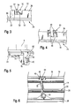
- a recess 44 is provided in the middle in the first longitudinal wall section 36 (FIG. 4), into which two parallel, spaced-apart latching tabs 46 extend.
- the latching tabs 46 protrude beyond the edge of the first longitudinal wall section 36 remote from the base plate 18 and are each provided with a wedge-shaped hook 48 at their end.
- each of the snap tabs 54 is in turn provided with a wedge-shaped hook 56 (FIG. 3).
- an elastic spring web 58 extends from the inside 52 of the second longitudinal wall section 38 to each of the snap tabs 54, each of which has its free end facing the hook 56 from the edge of the recess 50.
- the inner surfaces of the first longitudinal wall section 36 and of the second longitudinal wall section 38 are connected at the level of the recess 44 by the transverse web 30, the transverse web 30 expanding adjacent to the second longitudinal wall section 38 to form a receiving opening 60 (FIG. 6).
- the receiving opening 60 has the shape of a circular cylindrical tube and leads to the underside 24 of the base plate 18.
- a T-shaped antenna 62 having a central beam 64 and a cross beam 66, is attached to the frame 12.
- an extension is provided through which a connecting cable 68 exits the antenna 62.
- the connecting cable 68 is guided through the receiving opening 60, and the extension, which can be cylindrical and conical, for example, is inserted into the receiving opening 60, so that the antenna 62 is centered on the frame 12 in this way.
- the antenna 62 is also fixed to the frame 12 by means of three fastening points, namely in the region of the cutouts 50 between the snap tabs 54 and the spring bars 58 and by lugs 70 formed on the central bar 64, which interact with the latching tabs 46 by removing them from the wedge-shaped hooks 48 be engaged and thus form a locking connection.
- the antenna 62 can be easily and securely and stably mounted and attached to the frame 12.
- the frame 12 of the air vent 10 is preferably made of plastic, so that the electrical field of the antenna 62 is not affected.
- the T-shape of the antenna is particularly advantageous for attachment to the frame 12 since it does not reduce the outflow opening 26.
- the reflector 16 is designed as a cuboid basket made of a metal grid, for example of stamped sheet metal, with a bottom 72 and side surfaces 74.
- the opening of the basket is provided for receiving the frame 12.
- retaining tabs 76 are provided for fastening the reflector 16 (FIG. 5), which extend perpendicularly from the underside 24.
- the front side 78 of the retaining tab 76 pointing away from the throughflow opening 26 is flush with the outer edge of the base plate 18, while the rear side is supported by a web 79 against the underside 24 of the base plate 18.
- a wedge-shaped snap hook 80 is formed on the front side 78 of each retaining tab 76.
- the latter is placed over the holding tabs 76 with the side walls 74, the side walls 74 being elastically bent outwards by the snap hooks 80 until the snap hooks 80 snap into openings 82 in the side walls 74, so that the reflector 16 is secure is attached to the frame 12.
- the connecting cable 68 can simply be led out through the spaces between the metal grids.
- the air vent 10 can, for example, be attached to the trunk of a vehicle in a sheet metal cutout in order to compensate for an increased pressure in the interior of the vehicle through the non-return flaps 14.
- the air vent 10 can be installed very easily in the vehicle by plugging it with the connecting wall 32 into the sheet metal cutout in the vehicle.
- Fastening tabs 84 formed in the connecting wall 32 hold the air vent 10 firmly in the sheet metal cutout.
- a circumferential seal 86 on the top of the base plate seals the air vent 10.
- the antenna 62 is thus protected from mechanical damage and is shielded from interference sources inside the vehicle by the reflector 16.
Landscapes
- Physics & Mathematics (AREA)
- Thermal Sciences (AREA)
- Engineering & Computer Science (AREA)
- Mechanical Engineering (AREA)
- Fittings On The Vehicle Exterior For Carrying Loads, And Devices For Holding Or Mounting Articles (AREA)
- Air-Conditioning For Vehicles (AREA)
- Self-Closing Valves And Venting Or Aerating Valves (AREA)
Applications Claiming Priority (2)
| Application Number | Priority Date | Filing Date | Title |
|---|---|---|---|
| DE10136376 | 2001-07-26 | ||
| DE10136376 | 2001-07-26 |
Publications (2)
| Publication Number | Publication Date |
|---|---|
| EP1279531A2 true EP1279531A2 (fr) | 2003-01-29 |
| EP1279531A3 EP1279531A3 (fr) | 2003-11-05 |
Family
ID=7693139
Family Applications (1)
| Application Number | Title | Priority Date | Filing Date |
|---|---|---|---|
| EP02014963A Withdrawn EP1279531A3 (fr) | 2001-07-26 | 2002-07-09 | Bouche d'air |
Country Status (2)
| Country | Link |
|---|---|
| US (1) | US20030022616A1 (fr) |
| EP (1) | EP1279531A3 (fr) |
Families Citing this family (14)
| Publication number | Priority date | Publication date | Assignee | Title |
|---|---|---|---|---|
| DE60304538T2 (de) * | 2002-10-16 | 2007-04-05 | Trw Automotive Electronics & Components Gmbh & Co. Kg | Belüftungsdüse mit integriertem elektronischen Bauteil |
| CA2497636C (fr) * | 2004-02-18 | 2013-04-16 | Snyder National Corporation | Grille a registre et cadre de raccordement avec connexion detachable |
| US7339482B2 (en) * | 2005-09-30 | 2008-03-04 | The Boeing Company | Shipping container air-vent cover antenna housing |
| EP2046591A4 (fr) * | 2006-07-27 | 2010-04-21 | Collins & Aikman Prod Co | Fenetre d'aeration fournissant une diffusion |
| US7690598B1 (en) * | 2006-09-11 | 2010-04-06 | Plattner Wesley M | Aircraft exhaust vent assembly |
| DE102009050885A1 (de) * | 2009-10-27 | 2011-04-28 | Behr Gmbh & Co. Kg | Luftausströmer |
| DE102010012087B4 (de) * | 2010-03-19 | 2015-04-02 | Trw Automotive Electronics & Components Gmbh | Entlüftungsvorrichtung |
| US8651924B1 (en) * | 2010-05-06 | 2014-02-18 | The Boeing Company | Interlocking vent assembly for equalizing pressure in a compartment |
| US20160121692A1 (en) * | 2014-10-31 | 2016-05-05 | U.S. Farathane Corporation | Ventilation module & assembly with two stage injection molding formation of rigid frame and hingedly attached flaps and die/mold assembly for creating the ventilation module |
| US9845970B2 (en) | 2016-06-20 | 2017-12-19 | Michael Heinrichs | Air vent |
| USD827122S1 (en) | 2016-10-06 | 2018-08-28 | Michael Heinrichs | Air vent |
| US10887776B2 (en) * | 2017-07-21 | 2021-01-05 | Cable Television Laboratories, Inc. | Multiple access point backhaul |
| US10566685B2 (en) | 2017-09-15 | 2020-02-18 | Cnh Industrial America Llc | Integrated mounting for vehicle immobilizer system antenna |
| NL2023734B1 (en) * | 2019-08-30 | 2021-05-11 | Dutch Innovation In Air Treat B V | A gas flow system |
Family Cites Families (5)
| Publication number | Priority date | Publication date | Assignee | Title |
|---|---|---|---|---|
| US6068551A (en) * | 1997-12-04 | 2000-05-30 | Oremland; George Alan | Trunk ventilator |
| JPH11301363A (ja) * | 1998-04-17 | 1999-11-02 | Calsonic Corp | 車両の車載機器用アンテナ取付構造 |
| DE19962736C2 (de) * | 1999-12-23 | 2001-11-22 | Hirschmann Electronics Gmbh | Fahrzeugantenne |
| GB2366453A (en) * | 2000-08-31 | 2002-03-06 | Nokia Mobile Phones Ltd | An antenna device for a communication terminal |
| DE20100157U1 (de) * | 2001-01-05 | 2001-05-17 | TRW Automotive Electronics & Components GmbH & Co.KG, 67677 Enkenbach-Alsenborn | Entlüftungsgitter für Fahrzeuge |
-
2002
- 2002-07-09 EP EP02014963A patent/EP1279531A3/fr not_active Withdrawn
- 2002-07-22 US US10/200,651 patent/US20030022616A1/en not_active Abandoned
Non-Patent Citations (1)
| Title |
|---|
| None |
Also Published As
| Publication number | Publication date |
|---|---|
| US20030022616A1 (en) | 2003-01-30 |
| EP1279531A3 (fr) | 2003-11-05 |
Similar Documents
| Publication | Publication Date | Title |
|---|---|---|
| DE69208653T2 (de) | Verbinder mit Ringverriegelung | |
| EP1279531A2 (fr) | Bouche d'air | |
| DE102006011836B3 (de) | Befestigungselement | |
| EP2057043B1 (fr) | Dispositif pour fixer une unité d'airbag dans un sous-ensemble d'un véhicule automobile, en particulier dans un volant de direction, par enclenchement | |
| DE3633893A1 (de) | Abgedichteter tastschalter | |
| WO2006026956A1 (fr) | Element de fixation | |
| EP0847346B1 (fr) | Lame d'essuie-glace a brise-vent pour systemes essuie-glace de vehicules a moteur | |
| EP1240685A1 (fr) | Antenne pour vehicule | |
| WO2018001406A1 (fr) | Support de pièce plane pour la fixation d'une pièce plane à une structure de cadre d'une armoire électrique et armoire électrique correspondante | |
| DE19534205C2 (de) | Elektrischer Steckverbinder | |
| DE10210628C1 (de) | Vorrichtung zur spielfreien Ein-Mann Montage eines Anbauteils, oder einer Kfz-Dachantenne | |
| DE202017105243U1 (de) | W-förmige, geflügelte Federklammer mit mindestens einem verstärkendem Versteifungsblech | |
| EP1792361B1 (fr) | Dispositif de fixation d'une antenne de vehicule automobile | |
| EP1024061A2 (fr) | Connection entre un logement de gonfleur et un couvercle dans un module de coussin gonflable | |
| EP1681206B1 (fr) | Dispositif incluant un manchon d'étanchéité pour le passage entre des parties de véhicules, mobiles l'une par rapport à l'autre | |
| EP1489712B1 (fr) | Soulagement de contrainte pour câble électrique | |
| DE3927818C2 (fr) | ||
| EP2842204A1 (fr) | Dispositif de fixation et système comprenant un appareil ou un élément et un rail oméga | |
| DE4122898A1 (de) | Befestigungsanordnung | |
| EP3651603B1 (fr) | Assemblage de boucle de ceinture | |
| DE10034862B4 (de) | Elektrisches Kontaktelement | |
| EP0813010B1 (fr) | Calotte en matière plastique | |
| DE102004059815B4 (de) | Montageträger für Unterflurdose | |
| DE69303366T2 (de) | Elektromagnetische abschirmungsvorrichtung | |
| EP0548701B1 (fr) | Boîtier de connecteurs électriques et agencement de connexion |
Legal Events
| Date | Code | Title | Description |
|---|---|---|---|
| PUAI | Public reference made under article 153(3) epc to a published international application that has entered the european phase |
Free format text: ORIGINAL CODE: 0009012 |
|
| AK | Designated contracting states |
Designated state(s): AT BE BG CH CY CZ DE DK EE ES FI FR GB GR IE IT LI LU MC NL PT SE SK TR |
|
| AX | Request for extension of the european patent |
Extension state: AL LT LV MK RO SI |
|
| PUAL | Search report despatched |
Free format text: ORIGINAL CODE: 0009013 |
|
| AK | Designated contracting states |
Kind code of ref document: A3 Designated state(s): AT BE BG CH CY CZ DE DK EE ES FI FR GB GR IE IT LI LU MC NL PT SE SK TR |
|
| AX | Request for extension of the european patent |
Extension state: AL LT LV MK RO SI |
|
| AKX | Designation fees paid | ||
| REG | Reference to a national code |
Ref country code: DE Ref legal event code: 8566 |
|
| STAA | Information on the status of an ep patent application or granted ep patent |
Free format text: STATUS: THE APPLICATION IS DEEMED TO BE WITHDRAWN |
|
| 18D | Application deemed to be withdrawn |
Effective date: 20040506 |