EP1279965A2 - Interrupteur de test de la continuité activé par oscillateur - Google Patents
Interrupteur de test de la continuité activé par oscillateur Download PDFInfo
- Publication number
- EP1279965A2 EP1279965A2 EP02015795A EP02015795A EP1279965A2 EP 1279965 A2 EP1279965 A2 EP 1279965A2 EP 02015795 A EP02015795 A EP 02015795A EP 02015795 A EP02015795 A EP 02015795A EP 1279965 A2 EP1279965 A2 EP 1279965A2
- Authority
- EP
- European Patent Office
- Prior art keywords
- oscillator
- power
- circuit
- timer
- conductors
- Prior art date
- Legal status (The legal status is an assumption and is not a legal conclusion. Google has not performed a legal analysis and makes no representation as to the accuracy of the status listed.)
- Granted
Links
Images



Classifications
-
- G—PHYSICS
- G01—MEASURING; TESTING
- G01R—MEASURING ELECTRIC VARIABLES; MEASURING MAGNETIC VARIABLES
- G01R31/00—Arrangements for testing electric properties; Arrangements for locating electric faults; Arrangements for electrical testing characterised by what is being tested not provided for elsewhere
- G01R31/005—Testing of electric installations on transport means
- G01R31/008—Testing of electric installations on transport means on air- or spacecraft, railway rolling stock or sea-going vessels
-
- G—PHYSICS
- G01—MEASURING; TESTING
- G01R—MEASURING ELECTRIC VARIABLES; MEASURING MAGNETIC VARIABLES
- G01R31/00—Arrangements for testing electric properties; Arrangements for locating electric faults; Arrangements for electrical testing characterised by what is being tested not provided for elsewhere
- G01R31/005—Testing of electric installations on transport means
-
- G—PHYSICS
- G01—MEASURING; TESTING
- G01R—MEASURING ELECTRIC VARIABLES; MEASURING MAGNETIC VARIABLES
- G01R31/00—Arrangements for testing electric properties; Arrangements for locating electric faults; Arrangements for electrical testing characterised by what is being tested not provided for elsewhere
- G01R31/50—Testing of electric apparatus, lines, cables or components for short-circuits, continuity, leakage current or incorrect line connections
- G01R31/52—Testing for short-circuits, leakage current or ground faults
-
- G—PHYSICS
- G01—MEASURING; TESTING
- G01R—MEASURING ELECTRIC VARIABLES; MEASURING MAGNETIC VARIABLES
- G01R31/00—Arrangements for testing electric properties; Arrangements for locating electric faults; Arrangements for electrical testing characterised by what is being tested not provided for elsewhere
- G01R31/50—Testing of electric apparatus, lines, cables or components for short-circuits, continuity, leakage current or incorrect line connections
- G01R31/54—Testing for continuity
Definitions
- the present invention relates generally to test switches/circuits used in conjunction with sensors which monitor the condition or status of important or critical functions in powered vehicles.
- the invention relates to a test switch/circuit which is used to indicate the status of the electrical conductors connecting to a remote sensor and is powered by the same conductors over which the sensor indication is provided.
- the invention relates to a test switch/circuit used to verify the continuity of the conductor connection between a remote sensor and an alert indicator.
- Typical sensors provide an open circuit between two conductors under normal conditions and close the circuit permitting current to flow when a fault condition is sensed.
- the sensors are generally located at some distance from the cockpit and are connected to the status indicators in the cockpit by conductors which may run over great lengths through several bulkheads, conduits, terminal blocks, and connectors.
- a connection failure anywhere along the path from sensor to cockpit indicator provides an open circuit. In such a case, the sensor may properly close the circuit upon detection of an appropriate condition but such information never reaches the cockpit through the open circuit. Failure of the warning system conductors could lead to catastrophic results since a fault condition would not be distinguishable from an open circuit condition.
- sensors which detect contaminant particle accumulation in the lubricating or hydraulic systems. Many of these sensors use a magnet to draw metal particles out of the oil stream into contact with conductive electrodes on the face of the sensor.
- the sensor is normally placed in electrical series connection with a power source and an indicator lamp.
- One of the electrode contacts within the sensor is connected to ground either through a separate wire or by means of connection to the airplane chassis. The contacts within the sensor normally provide an open circuit so that no power is drawn through the indicator lamp.
- aircraft employ systems which check electrical continuity between critical sensors and the cockpit indicators each time the aircraft is powered up.
- indicator lamps in the cockpit associated with critical functions are turned on for a interval of time sufficient for the pilots to notice the failure of any lamp to light.
- These lamps are typically turned on by test means which connect the power and ground conductors of the lamp circuit at or very near the associated sensor; that is, the test means provides an alternate current path (short) in parallel with the sensor which completes the series circuit. After a predetermined time, the test means ceases to short the circuit and the indicator lamp will go off unless the sensor itself completes the circuit.
- the short circuit test means are generally powered from the same conductor that supplies power (voltage) to the sensor. This requires that power be drawn from the sensor conductor for operation of the test means.
- One problem which is encountered is that drawing much power to power the test means from the sensor circuit during the test period reduces the voltage or current available to power the indicator lamp. A dim lamp is less easily detected under bright cockpit conditions. In other undisclosed embodiments of the invention, where additional functionality has been added, available power may be diminished to power the lamp.
- Berrier teaches the use of a clock timer and sequencer in conjunction with a pulsing or intermittent switch which is placed in parallel with the sensor contacts. Closure of the switch across the leads shorts the sensor and permits current to flow through the power line turning on the lamp in the cockpit.
- the clock timer and sequencer control the duration of the test. Power is drawn from the sensor supply to power the clock timer and sequencer, but to avoid drawing too much power and dimming the lamp, the switch is not closed continuously but rather is opened and closed with a long duty cycle of approximately 90%.
- the shorting switch is a MOS-FET transistor and is closed for 29 milliseconds each cycle and open for 1 millisecond each cycle.
- a power supply capacitor to operate the circuit during the closed part of the cycle.
- the current through the lamp is pulsed, but at a rate imperceptible to the human eye.
- the continual opening and closing of the switch and abrupt power surges has the undesirable side effect of generating broadband electro- magnetic interference (EMI), high frequency signals associated with the Fourier transform of the voltage surge delta function each time the switch is opened or closed rapidly and repeatedly.
- EMI broadband electro- magnetic interference
- the invention described in this patent document provides a means for monitoring a piece of equipment such as an aircraft engine or transmission. More specifically, the present invention provides a means of testing the continuity of an electrical connection between an indicator and a remote sensor upon application of power to the circuit.
- the continuity test activates the indicator for a predetermined length of time if there is continuity of the conductor. After the completion of the desired test time, the test circuit no longer functions.
- the indicator lamp is not pulsed during the test time and full current is provided to the lamp generating its designed brightness. Further, the circuit across the sensor leads is not repetitively opened and closed and, therefore, no high frequency EMI is generated.
- the switch/circuit of the invention works in conjunction with monitoring circuits typically found in aircraft.
- the cockpit monitoring circuit may consist of an alarm lamp in series with a direct current power supply, or a logic assembly, or it may be formed from an operational amplifier configured as a voltage comparator.
- the current drawn through the sensor directly powers and illuminates the lamp.
- a logic circuit or voltage comparator When used with a logic circuit or voltage comparator, a low voltage on the sensor line causes the monitoring circuit to light a panel lamp.
- the comparator compares a reference voltage at a first input to the voltage at a second input which depends on the status of the sensor.
- the comparator If the voltage at the second input is lower than the reference voltage, the comparator provides an output signal which can be used to power a warning lamp illumination circuit. If the voltage at the second input is equal to or higher than the reference voltage, no output signal is provided and the lamp illumination circuit is not activated.
- the second input is connected to one side of a normally open sensor and a series resistor to supply voltage.
- the voltage at the second input is determined by whether the sensor is open or closed. In the open position, the sensor does not connect the input to ground, and the voltage remains high. In the closed position, the sensor connects the second input to ground, driving down the voltage, which in turn causes the comparator to activate the lamp illumination circuit.
- the test switch/circuit of this invention is also connected to the second input through the same conductor as the sensor. Upon power up, the oscillator part of the test switch/circuit is activated and appears as a short circuit (current path) to ground. Since the oscillator circuit serves the function of a switch by conducting current to ground, this patent document characterizes the invention by use of the term switch/circuit. If an indicator lamp is in series with the test circuit, current flows through the lamp and the test circuit to ground thereby illuminating the lamp. If a voltage comparator is used with the test circuit, the oscillator short to ground drives down the voltage at the second input and causes the comparator to activate the lamp illumination circuit.
- the test switch/circuit contains a timing function which turns off the oscillator circuit after a predetermined time so that it no longer appears as a short circuit (current path) to ground, voltage at the second input rises and the comparator no longer activates the lamp illumination circuit.
- the oscillator part of the circuit responsible for appearing as a short circuit (current path) to ground may also be used as an electronic switch in conjunction with a mechanical connection which moves the ferromagnetic core of a transformer in the oscillator circuit thereby decoupling the primary and secondary windings of the transformer.
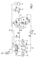
- an indicator lamp B1 in an electrical series circuit through conductor 4 to one side of chip sensor 5 located in the lubricating oil of an engine or power train (not shown) or a hydraulic system. Electrical power is supplied to the circuit when aircraft instruments are switched on at power-up.
- Sensor 5 contains a magnet 7 which draws metallic chips to contacts 6 .
- One plate of sensor 5 is connected to conductor 4 while the other plate is connected to ground. Examples of this sensor type are disclosed in U.S. Patents 3,432,750, 3,753,442 and 4,070,660.
- a second sensor 8 may also be connected to conductor 4 to provide indications of other functions such as loss of oil/hydraulic fluid.
- a direct current voltage source V IN is connected to one side of lamp B1.
- the test switch/circuit is electrically connected to conductor 4 at point 9 which is located in close physical proximity to sensor 5.
- the test circuit has a step up transformer 10 with two primary coils P1 and P2, and a secondary coil S. Each primary coil has M turns and the secondary has N turns.
- Primary coil P1 is connected to the drain of MOS-FET transistor T1 and primary coil P2 is connected to the drain of MOS-FET transistor T2.
- the sources of transistors T1 and T2 are connected to ground.
- the two ends of the secondary coil are connected to the gates of T1 and T2.
- Bias resistor R2 connects conductor 4 directly to the gate of transistor T2 and the gate of T1 through the secondary winding S.
- Diodes D1 and D2 are connected to the gates of T1 and T2 and the common anodes are connected to ground.
- Zener diode Z1 is connected to the gate of T1 and zener diode Z2 is connected to the gate of T2.
- the two Zener diode cathodes are common and connected to line 11 which is in series with resistor R4 to the drain of MOS-FET transistor T3.
- the source of transistor T3 is connected to ground.
- the gate of transistor T3 is connected to the output of counter timer IC1.
- a current limiting resistor R3 connects bias resistor R2 to the clock input of counter timer IC1.
- Diode D3 connects current limiting resistor R3 to one input 12 of capacitor C1, the power input of counter timer IC1, and the power input of voltage monitor IC2.
- the other side of capacitor C1 is connected to ground as is the ground input of counter timer IC1.
- Voltage monitor IC2 is connected across capacitor C1.
- the output of voltage monitor IC2 is connected to the reset input of counter timer IC1.
- Counter timer IC1 has several selection leads indicated at "SELECT" which may be either open or shorted to ground.
- Transformer 10 transistors T1 and T2, diodes D1 and D2, zener diodes Z1 and Z2, and bias resistor R2 comprise a self-powered astable low power oscillator.
- the voltage rises on conductor 4 and is applied to the dual primary windings P1 and P2 of transformer 10 and through them to the drain of MOSFET transistors T1 and T2.
- Simultaneously voltage is applied to the gate of transistor T2 through bias resistor R2.
- the low power oscillator is off until the voltage on conductor 4 reaches several volts when the voltage provided by bias resistor R2 becomes sufficient to turn on transistor T2 .
- Transistor T2 then draws current through primary winding P2 directly to ground. At this point, the low power oscillator starts up and runs generating a periodic waveform of approximately 75 KHz.
- the voltage of the wave form is a function of the turns ratio N/M of the transformer primary and secondary coils. In the preferred embodiment M is 2 and N is 200 yielding a 100:1 voltage step up. Typically the peak to peak voltage will be several volts.
- the waveform output of the secondary at point 25 is shown in Figure 2. Diodes D1 and D2 provide a return path for the drive current from the alternating waveform out of the transformer secondary S into transistor switches T1 and T2.
- Zener diodes Z1 and Z2 provide over-voltage burn out protection to switch transistors T1 and T2. As will be seen, loading resistor R4 and switch transistor T3 are used to turn off the low power oscillator.
- the oscillator circuit When configured in the embodiment with the values of the components set forth above, the oscillator circuit has the unique characteristic of operating with an input voltage drop of less than 200 millivolts across the primary windings P1 and P2 from conductor 4 at point 9 to ground. While the oscillator runs, the lamp is turned on indicating that there is continuity in the sensor conductor circuit up to point 9.
- timing and turning off of the lamp is accomplished as follows.
- the low power oscillator alternating waveform is used as a clocking signal and time reference by applying it through current limiting resistor R3 to the clock input of integrated circuit counter timer IC1.
- Integrated circuit counter timer IC1 is a multi-stage binary counter timer. One of several counter output lines of IC1 can be selected and connected to the output pin of IC1 by the four wire jumper connections indicated at "SELECT".
- the alternating waveform frequency and the value of the counter used to end the timer cycle set the duration time during which the oscillator runs and the panel lamp is illuminated.
- Power is supplied to IC1 both through bias resistor R2 and through the alternating waveform output of the oscillator.
- the alternating oscillator output is rectified by diode D3 and applied to the power input of IC1, the power input of voltage monitor IC2, and capacitor C1.
- Capacitor C1 is slowly charged up and provides even power to IC1.
- Voltage monitor IC2 is used to generate a "clear reset" signal into counter IC1 during power up until IC1 is ready to count clock pulses and begin the timing cycle. When the voltage across capacitor C1 increases above 3.5 volts, the reset signal from IC2 ends which allows counter IC1 to begin counting the clock pulses and begin the timing cycle.
- the output of IC1 goes high.
- the high signal applied to the gate of transistor T3 connects the gates of transistors T1 and T2 to ground through resistor R4 and zener diodes Z1 and Z2 thereby turning off the oscillator. Once the oscillator is turned off, it no longer acts like a short to ground of conductor 4 and no current flows through lamp B1.
- the output of IC1 stays high as long as the power V IN is supplied to the system. Thus the switch/circuit of this invention stays deactivated until the aircraft system is powered down and up again.
- test circuit switch of this invention behaves as follows.
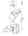
- Figure 3 shows such a voltage comparator circuit. Again, the operation of the monitoring part of the switch/circuit of the invention will first be described assuming that the switch/circuit starting at point 9 is not connected.
- the nominal values of additional voltages and components are as follows:
- V REF is set very low with respect to V IN .
- conductor 4 is not grounded provided that metallic chips do not bridge the contacts 6 in sensor 5.
- voltage V IN is applied to input 2 of comparator A1, and, since it is substantially greater than V REF no signal is produced at the output 3 of comparator A1 to activate the lamp illumination circuit.
- conductor 4 is connected by sensor 5 to ground. In this case current flows through resistor R1 causing the voltage at input 2 of comparator A1 to drop to near zero.
- Comparator A1 now sees a lower voltage on input 2 than on input 1 and provides an output signal at 3 to activate a lamp illuminating circuit and the lamp will stay on continuously.
- the switch of the invention operates as follows.
- the oscillator behaves upon power-up as previously described.
- V REF is set higher than the approximately 200 millivolt drop across the oscillator from conductor 4 to ground, the oscillator switch/circuit looks like a short circuit to comparator A1.
- the voltage at comparator input 2 is below V REF at input 1 so that the comparator produces an output at 3 which activates the lamp illumination circuit.
- the lamp is turned on, again indicating that there is continuity in the sensor circuit up to point 9.
- the timing function also works as previously described.
- the internal oscillator frequency of IC1 is used as a basis for counting to determine the duration of the test cycle instead of the frequency of the waveform output of the oscillator.
- Figure 4 shows the preferred timing circuit used with a series connected panel lamp. Upon the application of V IN the oscillator circuit acts as previously described. Current flows through lamp B1 and the oscillator to ground. Once illuminated, the lamp will stay on until the oscillator is turned off. Power is again provided to IC1 and voltage monitor IC2 through resistor R3 and diode D3 . Additional power may be provided through resistor R5 and diode D4.
- the input voltage to IC1 and IC2 is regulated by zener diode Z3 and capacitor C2 which are connected between the power input conductor and ground.
- voltage monitor IC2 is used to generate a "clear reset" signal into counter IC1 during power-up until IC1 is ready to count the internal oscillator frequency and begin the timing cycle.
- the internal oscillator frequency is determined by the values of C3, R6, and R7.
- the output of the internal oscillator is counted until a predetermined value set by the select lines is reached.
- the output of IC1 goes high and causes transistor T3 to connect the gates of transistors T1 and T2 to ground thereby turning off the oscillator. No current can then flow through lamp B1, and it is no longer illuminated as the end of the timed interval has been reached.
- the nominal values of additional voltages and components are as follows:
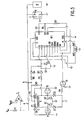
- Figure 5 shows the preferred timing circuit used in conjunction with a voltage comparator illumination circuit.
- the comparator circuit operates as described above for the first timing circuit, the difference being the use of the internal oscillator of IC1 to determine the time during which the oscillator will run.
- the switch/circuit oscillator of this invention provides essentially a constant short circuit (current path) to ground while it is running, the lamp illumination circuit, whether consisting of just a lamp bulb, a logic circuit, a voltage comparator, or some other responsive circuit is constantly operated until the oscillator turns off after a predetermined time. This means that the lamp, when turned on, is provided with a constant voltage and shines at its designed brightness. Also, no repetitive switched voltage pulsing with its associated broadband EMI is generated by the switch/circuit of this invention. In vehicles and especially planes which are not constructed of electrically conducting materials, the ground to the sensor and test switch/circuit can be provided by a second conductor.
- the panel light will not illuminate on power-up thereby indicating a fault which should be resolved before the vehicle is used.
- different monitoring circuits are used in aircraft and may be employed with the test switch of this invention. All that is necessary is that the monitoring circuit be responsive to a voltage drop approximating a short circuit on the power conductor connected to the sensor.
- the oscillator circuit can be used as a switch in other applications where a reliable electronic switch is required.
- Figure 6 shows one such application where the timing circuit has been eliminated.
- the oscillator circuit will turn on as described above when power is applied to conductor 4.
- current flow in the primaries will not induce a voltage in the secondary and the oscillator will not turn on and appear as a short circuit (current path).
- Removal of the ferromagnetic core 12 from transformer 10 can sufficiently decouple the primary and secondary windings.
- the ferromagnetic core 12 is attached to a mechanical activator 13 in a sensor which moves in accordance with the desired status of the sensor.
- such a sensor may be designed to sense the presence of air pressure at a given level.
- the transformer core 12 attached to activator 13 is withdrawn from transformer 10.
- the oscillator can not turn on since no magnetic flux connects the primary and secondary coils.
- the sensor responds causing the transformer coupling to increase between the primary and secondary windings of the transformer. In the embodiment shown, this is achieved by inserting core 12 into transformer 10 .
- the oscillator circuit turns on and appears as a short circuit (current path) permitting current to flow and turning on the panel lamp as described above or activates other appropriate circuits.
Landscapes
- Physics & Mathematics (AREA)
- General Physics & Mathematics (AREA)
- Testing Of Short-Circuits, Discontinuities, Leakage, Or Incorrect Line Connections (AREA)
Applications Claiming Priority (2)
| Application Number | Priority Date | Filing Date | Title |
|---|---|---|---|
| US09/911,941 US6587050B2 (en) | 2001-07-24 | 2001-07-24 | Oscillator activated continuity testing switch |
| US911941 | 2001-07-24 |
Publications (3)
| Publication Number | Publication Date |
|---|---|
| EP1279965A2 true EP1279965A2 (fr) | 2003-01-29 |
| EP1279965A3 EP1279965A3 (fr) | 2004-03-03 |
| EP1279965B1 EP1279965B1 (fr) | 2009-11-25 |
Family
ID=25431132
Family Applications (1)
| Application Number | Title | Priority Date | Filing Date |
|---|---|---|---|
| EP02015795A Expired - Lifetime EP1279965B1 (fr) | 2001-07-24 | 2002-07-15 | Interrupteur de test de la continuité activé par oscillateur |
Country Status (5)
| Country | Link |
|---|---|
| US (1) | US6587050B2 (fr) |
| EP (1) | EP1279965B1 (fr) |
| JP (1) | JP2003177152A (fr) |
| CA (1) | CA2393416C (fr) |
| DE (1) | DE60234488D1 (fr) |
Cited By (1)
| Publication number | Priority date | Publication date | Assignee | Title |
|---|---|---|---|---|
| EP1293786A3 (fr) * | 2001-09-14 | 2004-07-28 | Eaton Corporation | Dispoitif et procédé pour tester la continuité et pour indiquer l'état d'un capteur |
Families Citing this family (8)
| Publication number | Priority date | Publication date | Assignee | Title |
|---|---|---|---|---|
| US7095283B2 (en) * | 2003-10-28 | 2006-08-22 | Axiom Microdevices, Inc. | Supply circuit for power amplifier drivers |
| DE10351387A1 (de) * | 2003-11-04 | 2005-06-23 | Fraunhofer-Gesellschaft zur Förderung der angewandten Forschung e.V. | Schaltervorrichtung |
| WO2009026038A1 (fr) * | 2007-08-16 | 2009-02-26 | Radian Research, Inc. | Appareil et procédé pour tester un transformateur d'instruments |
| US8981265B2 (en) | 2008-12-30 | 2015-03-17 | Ppg Industries Ohio, Inc. | Electric circuit and sensor for detecting arcing and a transparency having the circuit and sensor |
| GB201200493D0 (en) * | 2012-01-12 | 2012-02-22 | Jaguar Cars | Vehicle test and diagnostics arrangement and method (switch pack actuation) |
| US10705039B2 (en) * | 2017-03-27 | 2020-07-07 | Nabtesco Corporation | Sensor for detecting magnetic powders in a lubricant |
| CN112785812B (zh) * | 2021-01-13 | 2022-07-05 | 铜陵市金鑫人防工程防护设备有限公司 | 一种地铁区间防护密闭门监测系统 |
| US12553957B2 (en) | 2024-01-05 | 2026-02-17 | BorgWarner US Technologies LLC | Systems and methods for testing a capacitor in a circuit |
Family Cites Families (48)
| Publication number | Priority date | Publication date | Assignee | Title |
|---|---|---|---|---|
| US838823A (en) | 1904-10-22 | 1906-12-18 | Safety Car Heating & Lighting | Low-water alarm. |
| US2782401A (en) | 1953-09-03 | 1957-02-19 | King Seeley Corp | Plural condition responsive signal system with initial testing |
| US2928037A (en) | 1954-12-02 | 1960-03-08 | Avien Inc | Thermistor liquid level switch |
| US2845614A (en) | 1956-09-19 | 1958-07-29 | Gen Motors Corp | Signal device test circuit |
| US3059443A (en) | 1959-01-29 | 1962-10-23 | Arthur Berryman | Alarm apparatus for refrigeration systems and the like |
| NL275018A (fr) | 1961-02-24 | |||
| US3149319A (en) | 1961-05-26 | 1964-09-15 | Ripley Ind Inc | Bowling foul indicator |
| US3155956A (en) | 1963-02-15 | 1964-11-03 | Beloit Corp | Bearing failure predicting device |
| US3335334A (en) | 1963-07-08 | 1967-08-08 | Molson Breweries Ltd | Liquid level sensing device |
| US3246517A (en) | 1963-07-15 | 1966-04-19 | Ford Motor Co | Transducer system |
| FR1389869A (fr) | 1964-03-24 | 1965-02-19 | Dispositif formant sonde ou analogue pour le contrôle de niveau de liquides électroconducteurs dans un réservoir et ses diverses applications | |
| GB1096278A (en) | 1964-04-28 | 1967-12-20 | Dipstix Ltd | Improvements in or relating to liquid level indicators |
| US3461446A (en) | 1965-07-02 | 1969-08-12 | Scully Signal Corp | Fluid-level detecting apparatus |
| US3498131A (en) | 1967-08-29 | 1970-03-03 | Eltop Corp | Liquid level measuring or indicating device |
| GB1232020A (fr) | 1967-10-18 | 1971-05-19 | ||
| US3588891A (en) | 1968-03-07 | 1971-06-28 | Beta Corp | Self-monitoring field-contacts for automatic alarm systems |
| US3601655A (en) | 1970-05-25 | 1971-08-24 | Chrysler Corp | Circuit continuity monitoring, warning and proving device |
| US3766537A (en) | 1971-05-03 | 1973-10-16 | Theodore D Bross Line Construc | A.c. powered surveillance system |
| BE793396A (fr) | 1972-01-24 | 1973-06-28 | Siemens Ag | Montage de surveillance de liaison |
| SE375395B (fr) | 1972-04-13 | 1975-04-14 | Impulsregulator Lycksele Ab | |
| JPS53145Y2 (fr) | 1973-12-14 | 1978-01-06 | ||
| US3963981A (en) | 1974-10-09 | 1976-06-15 | J. M. Richards Laboratories | Leakage and continuity tester |
| US3955183A (en) | 1975-01-06 | 1976-05-04 | The Mosler Safe Company | Alarm condition sensing and indicating circuit with test capability |
| JPS51122751A (en) | 1975-04-21 | 1976-10-27 | Yokogawa Hokushin Electric Corp | D-c control currint supply means |
| US3978477A (en) | 1975-05-29 | 1976-08-31 | Westinghouse Electric Corporation | Automatic test sequence circuit for a security system |
| US4070660A (en) * | 1976-02-20 | 1978-01-24 | Tauber Thomas E | Wear particle detector |
| US4150369A (en) | 1976-10-22 | 1979-04-17 | Gaspari Russell A | Intrusion alarm system |
| US4176350A (en) | 1977-05-18 | 1979-11-27 | Patterson Billy J | Indicator to show whether a switch has opened |
| US4127808A (en) | 1977-10-07 | 1978-11-28 | The United States Of America As Represented By The Secretary Of The Air Force | Engine chip detector |
| US4166243A (en) | 1978-04-21 | 1979-08-28 | General Motors Corporation | Thermocouple failure detector |
| US4219805A (en) | 1978-10-13 | 1980-08-26 | Technical Development Company | Lubricating oil debris monitoring system |
| DE2851333A1 (de) | 1978-11-28 | 1980-06-12 | Bosch Gmbh Robert | Pruefschaltung fuer die ausloesevorrichtung einer den schutz der insassen eines fahrzeugs waehrend eines unfalles dienenden sicherheitseinrichtung |
| US4302754A (en) | 1979-02-12 | 1981-11-24 | Technical Development Co. | Wear particle disintegrator monitor |
| US4236146A (en) | 1979-04-09 | 1980-11-25 | S. A. Clark & Associates | Switchless circuit malfunction sensor |
| US4354180A (en) | 1980-12-19 | 1982-10-12 | Genelco, Inc. | Electro-optical liquid level sensor |
| JPS6017157B2 (ja) | 1981-02-25 | 1985-05-01 | ニツタン株式会社 | 選択作動可能な火災感知器 |
| GB2094487B (en) * | 1981-03-09 | 1984-08-22 | Ml Aviation Co Ltd | Explosive device including an ignition circuit monitor |
| EP0063011A3 (fr) | 1981-04-09 | 1983-06-29 | Imperial Chemical Industries Plc | Dispositif d'essai |
| US4544910A (en) * | 1982-05-10 | 1985-10-01 | Max Hoberman | Exit sign lamp flashing system with self-checking provisions |
| GB2123567A (en) * | 1982-06-29 | 1984-02-01 | Redland Automation Ltd | A method and apparatus for checking the integrity of a wire |
| US4517161A (en) | 1982-09-29 | 1985-05-14 | Grumman Aerospace Corp. | Combustible vapor detection system |
| US4574266A (en) * | 1983-06-13 | 1986-03-04 | Motorola, Inc. | Electrical load monitoring system and method |
| US4667187A (en) | 1986-01-08 | 1987-05-19 | Ford Motor Company | Lamp failure monitoring system |
| US4831362A (en) | 1986-05-16 | 1989-05-16 | Aeroquip Corporation | Failure detection system for a metallic debris detection system |
| US4799019A (en) | 1987-03-02 | 1989-01-17 | Charles Cooley | Electrical continuity load monitoring circuit |
| US5045840A (en) * | 1989-06-06 | 1991-09-03 | Benz Companies, Inc. | Device for sensing continuity in a circuit having an open circuited apparatus |
| US5294909A (en) | 1993-01-07 | 1994-03-15 | Barber-Colman Company | Resistive sensor for position detection of manifold failures |
| WO1996004630A1 (fr) * | 1994-08-03 | 1996-02-15 | Drexelbrook Controls, Inc. | Systeme de controle extremement fiable |
-
2001
- 2001-07-24 US US09/911,941 patent/US6587050B2/en not_active Expired - Fee Related
-
2002
- 2002-07-15 DE DE60234488T patent/DE60234488D1/de not_active Expired - Lifetime
- 2002-07-15 CA CA002393416A patent/CA2393416C/fr not_active Expired - Fee Related
- 2002-07-15 EP EP02015795A patent/EP1279965B1/fr not_active Expired - Lifetime
- 2002-07-24 JP JP2002215156A patent/JP2003177152A/ja active Pending
Cited By (1)
| Publication number | Priority date | Publication date | Assignee | Title |
|---|---|---|---|---|
| EP1293786A3 (fr) * | 2001-09-14 | 2004-07-28 | Eaton Corporation | Dispoitif et procédé pour tester la continuité et pour indiquer l'état d'un capteur |
Also Published As
| Publication number | Publication date |
|---|---|
| JP2003177152A (ja) | 2003-06-27 |
| US6587050B2 (en) | 2003-07-01 |
| US20030020620A1 (en) | 2003-01-30 |
| EP1279965A3 (fr) | 2004-03-03 |
| CA2393416A1 (fr) | 2003-01-24 |
| DE60234488D1 (de) | 2010-01-07 |
| EP1279965B1 (fr) | 2009-11-25 |
| CA2393416C (fr) | 2009-10-27 |
Similar Documents
| Publication | Publication Date | Title |
|---|---|---|
| US6201318B1 (en) | Headlight warning system | |
| EP0053130B1 (fr) | Detecteur d'ondulation pour systemes de charge de batterie alternateur de vehicule automabile | |
| US5446444A (en) | Capacitive threshold detector test circuit | |
| US5959537A (en) | Variable trip fault indicator | |
| US6587050B2 (en) | Oscillator activated continuity testing switch | |
| US4689573A (en) | On-vehicle diagnostic unit for electronic ignition systems | |
| US6523400B1 (en) | Method and apparatus for detecting timing belt damage using link-coupled feedback | |
| US7561396B2 (en) | Apparatus for monitoring open state of the secondary terminals of a current transformer | |
| JPH01172710A (ja) | 液面位置を測定する装置及び方法 | |
| US20150137679A1 (en) | Led signal lamp | |
| US5406208A (en) | Method and apparatus for eliminating chips in a chip detection circuit and for determining chip size | |
| US5247280A (en) | Combination vehicle flasher having first and second flash rates and duty rates | |
| US5250909A (en) | Automatic fault detection system in electrical sensing circuit | |
| CA2403069C (fr) | Verificateur multifonctions de continuite et autres parametres | |
| US4656464A (en) | Liquid level detector | |
| US4823625A (en) | Contaminant sensing system | |
| US4134101A (en) | Protective circuit for electronic motor vehicle engine operating timers | |
| US4539547A (en) | Low liquid level sensing and warning circuit | |
| US4668946A (en) | System for detecting the failure of a filament lamp | |
| CN207832935U (zh) | 电子部件短路检测装置 | |
| CA1279697C (fr) | Verificateur de resistances de bornes d'element de stockage d'energie monte dans un circuit electrique | |
| EP0360405A2 (fr) | Capteur du niveau du réfrigérant à deux fils | |
| US4862094A (en) | Stroboscopic light circuit diagnostic system | |
| KR930011101B1 (ko) | 모니터 회로 | |
| US5304919A (en) | Electronic constant current and current pulse signal generator for nuclear instrumentation testing |
Legal Events
| Date | Code | Title | Description |
|---|---|---|---|
| PUAI | Public reference made under article 153(3) epc to a published international application that has entered the european phase |
Free format text: ORIGINAL CODE: 0009012 |
|
| AK | Designated contracting states |
Designated state(s): AT BE BG CH CY CZ DE DK EE ES FI FR GB GR IE IT LI LU MC NL PT SE SK TR |
|
| AX | Request for extension of the european patent |
Extension state: AL LT LV MK RO SI |
|
| PUAL | Search report despatched |
Free format text: ORIGINAL CODE: 0009013 |
|
| AK | Designated contracting states |
Kind code of ref document: A3 Designated state(s): AT BE BG CH CY CZ DE DK EE ES FI FR GB GR IE IT LI LU MC NL PT SE SK TR |
|
| AX | Request for extension of the european patent |
Extension state: AL LT LV MK RO SI |
|
| RIC1 | Information provided on ipc code assigned before grant |
Ipc: 7G 01R 31/28 B Ipc: 7G 01R 31/00 B Ipc: 7G 01R 31/02 A |
|
| 17P | Request for examination filed |
Effective date: 20040426 |
|
| AKX | Designation fees paid |
Designated state(s): BE DE FR GB IT |
|
| 17Q | First examination report despatched |
Effective date: 20050408 |
|
| 17Q | First examination report despatched |
Effective date: 20050408 |
|
| GRAP | Despatch of communication of intention to grant a patent |
Free format text: ORIGINAL CODE: EPIDOSNIGR1 |
|
| GRAS | Grant fee paid |
Free format text: ORIGINAL CODE: EPIDOSNIGR3 |
|
| GRAA | (expected) grant |
Free format text: ORIGINAL CODE: 0009210 |
|
| AK | Designated contracting states |
Kind code of ref document: B1 Designated state(s): BE DE FR GB IT |
|
| REG | Reference to a national code |
Ref country code: GB Ref legal event code: FG4D |
|
| REF | Corresponds to: |
Ref document number: 60234488 Country of ref document: DE Date of ref document: 20100107 Kind code of ref document: P |
|
| PLBE | No opposition filed within time limit |
Free format text: ORIGINAL CODE: 0009261 |
|
| STAA | Information on the status of an ep patent application or granted ep patent |
Free format text: STATUS: NO OPPOSITION FILED WITHIN TIME LIMIT |
|
| 26N | No opposition filed |
Effective date: 20100826 |
|
| PGFP | Annual fee paid to national office [announced via postgrant information from national office to epo] |
Ref country code: GB Payment date: 20140624 Year of fee payment: 13 |
|
| PGFP | Annual fee paid to national office [announced via postgrant information from national office to epo] |
Ref country code: DE Payment date: 20140731 Year of fee payment: 13 |
|
| PGFP | Annual fee paid to national office [announced via postgrant information from national office to epo] |
Ref country code: FR Payment date: 20140624 Year of fee payment: 13 |
|
| PGFP | Annual fee paid to national office [announced via postgrant information from national office to epo] |
Ref country code: IT Payment date: 20140717 Year of fee payment: 13 |
|
| PGFP | Annual fee paid to national office [announced via postgrant information from national office to epo] |
Ref country code: BE Payment date: 20140708 Year of fee payment: 13 |
|
| REG | Reference to a national code |
Ref country code: DE Ref legal event code: R119 Ref document number: 60234488 Country of ref document: DE |
|
| GBPC | Gb: european patent ceased through non-payment of renewal fee |
Effective date: 20150715 |
|
| PG25 | Lapsed in a contracting state [announced via postgrant information from national office to epo] |
Ref country code: IT Free format text: LAPSE BECAUSE OF NON-PAYMENT OF DUE FEES Effective date: 20150715 Ref country code: DE Free format text: LAPSE BECAUSE OF NON-PAYMENT OF DUE FEES Effective date: 20160202 Ref country code: GB Free format text: LAPSE BECAUSE OF NON-PAYMENT OF DUE FEES Effective date: 20150715 |
|
| REG | Reference to a national code |
Ref country code: FR Ref legal event code: ST Effective date: 20160331 |
|
| PG25 | Lapsed in a contracting state [announced via postgrant information from national office to epo] |
Ref country code: FR Free format text: LAPSE BECAUSE OF NON-PAYMENT OF DUE FEES Effective date: 20150731 |
|
| PG25 | Lapsed in a contracting state [announced via postgrant information from national office to epo] |
Ref country code: BE Free format text: LAPSE BECAUSE OF NON-PAYMENT OF DUE FEES Effective date: 20150731 |