EP1280032A1 - Spannungsregler mit kleiner Verlustspannung - Google Patents
Spannungsregler mit kleiner Verlustspannung Download PDFInfo
- Publication number
- EP1280032A1 EP1280032A1 EP01402036A EP01402036A EP1280032A1 EP 1280032 A1 EP1280032 A1 EP 1280032A1 EP 01402036 A EP01402036 A EP 01402036A EP 01402036 A EP01402036 A EP 01402036A EP 1280032 A1 EP1280032 A1 EP 1280032A1
- Authority
- EP
- European Patent Office
- Prior art keywords
- voltage
- transistor
- circuit
- current source
- regulator
- Prior art date
- Legal status (The legal status is an assumption and is not a legal conclusion. Google has not performed a legal analysis and makes no representation as to the accuracy of the status listed.)
- Withdrawn
Links
- 230000001105 regulatory effect Effects 0.000 claims abstract description 13
- 230000007423 decrease Effects 0.000 description 3
- 238000000034 method Methods 0.000 description 3
- 230000033228 biological regulation Effects 0.000 description 1
Images


Classifications
-
- G—PHYSICS
- G05—CONTROLLING; REGULATING
- G05F—SYSTEMS FOR REGULATING ELECTRIC OR MAGNETIC VARIABLES
- G05F1/00—Automatic systems in which deviations of an electric quantity from one or more predetermined values are detected at the output of the system and fed back to a device within the system to restore the detected quantity to its predetermined value or values, i.e. retroactive systems
- G05F1/10—Regulating voltage or current
- G05F1/46—Regulating voltage or current wherein the variable actually regulated by the final control device is DC
- G05F1/56—Regulating voltage or current wherein the variable actually regulated by the final control device is DC using semiconductor devices in series with the load as final control devices
- G05F1/575—Regulating voltage or current wherein the variable actually regulated by the final control device is DC using semiconductor devices in series with the load as final control devices characterised by the feedback circuit
Definitions
- the present invention is related to supply regulators, more particularly to voltage regulator circuits of the low drop type.
- Supply regulators are commonly used throughout electric and electronic equipment to provide a stable voltage or current supply from an input that may vary in time and over different load conditions.
- Low drop regulators are known to perform well and are in high demand due to their high stability and low energy losses.
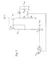
- Current low-drop regulators (see fig. 1) have a standard basic output circuit consisting of a p-type current mirror (T 4 , T 5 ) wherein the driving circuit (T 4 ) is in saturation.
- the voltage drop across T 5 can only be reduced by having a small on-resistance R on , thus by a combination of a high V GS , and by a large W/L ratio.
- V GS very high V GS is difficult due to the quadratic I/V relationship of the current through T 4 (the gain in V GS is very small compared to the current increase that is needed). So a very large PMOS for T 5 and/or a very big current through T 4 is needed to obtain a satisfying result.
- the regulator device is a regulator transistor
- said regulator transistor has a fixed gate voltage
- said first current source is directly coupled to the gate of said follower transistor.
- the voltage regulator circuit further comprises a biasing transistor and a second current source arranged to provide the fixed gate voltage of the regulator transistor.
- the fixed gate voltage is preferably selected such that for a certain maximal current I max through the driver transistor, the driver transistor is in linear mode of operation.
- a voltage regulator circuit can further comprise an input terminal for applying a reference voltage.
- the comparator circuit is an error amplifier arranged to generate an output voltage at an output node based upon a voltage difference between said regulated output voltage and said reference voltage.
- a voltage regulator circuit has preferably said driver transistor and said follower transistor interconnected at their gate, both transistors being connected with their source to said input terminal, the output terminal being the drain of the follower transistor.
- Said first current source is preferably interposed between said output node of said error amplifier and the drain of said driver transistor.
- the current mirror circuit is of the p-type.
- Fig. 1 represents the standard basic low-drop regulator circuit from the prior art. bipolar transistors. The latter therefore requires the availability of an expensive BICMOS process.
- the present invention aims to provide a new low drop regulator which is low-cost, can be realised using CMOS processing, which is stable, modest in power consumption and which performs well.
- the present invention concerns a voltage regulator circuit for providing a regulated output voltage (V out ) at an output terminal, said regulator circuit comprising
- circuit operatively linked as to regulate an input voltage V in to said regulated output voltage by comparing said output voltage with a reference voltage and adjusting said first current source to maintain said regulated output voltage at said output terminal, characterised in that the circuit further comprises a regulator device interposed between said first current source and said driver transistor.
- Said regulator device is preferably selected from the group consisting of a regulator resistor and regulator transistor.
- Fig. 2 represents a preferred embodiment of the new regulator circuit according to the present invention.
- Fig. 3 represents another embodiment of the new regulator circuit according to the present invention.
- the present invention provides a low-cost pure CMOS alternative to the solutions known in the art.
- One of the prior art low-drop regulators is,by means of reference, shown in Fig. 1.
- Such a low-drop regulator provides a regulated output voltage V out at a same named output terminal, from an input voltage Vin, which is an input signal to this voltage regulator circuit at a same named input terminal, by comparing said output voltage with a reference voltage V ref , provided to the voltage regulator at a same named input terminal, and by adjusting a first current source, denoted I2, to maintain the regulated output voltage at the output terminal.
- a first current source denoted I2
- the voltage regulator circuit further comprises a current mirror circuit, comprising a driver transistor (T 4 ) and a follower transistor (T 5 ), interposed between said first current source and said output terminal.
- the main feature of the present invention consists in the addition to this prior art circuit, of a regulator device for creating a more suitable current/voltage characteristic for driving the follower transistor T 5
- This current/voltage characteristic is preferably an s-type voltage/current characteristic.
- Said regulator device can e.g. be a resistor or, more preferably, a transistor circuit.
- an additional transistor (T sol ) is added in series with T 4 , whereby this additional transistor is driven by a fixed gate voltage denoted V G .
- This gate voltage V G is such that for a certain maximum current I max through T 4 , T 4 will be driven in its linear mode of operation such that the current source I 2 will force the voltage on the gate of T 5 low.
- V GS of T 5 will thus increase substantially more compared to the saturation region. This thus allows T 5 to conduct much larger currents compared to the prior art case, such that T 5 can accordingly be made much smaller for having the same output current as in the prior art.
- the fixed V G can be obtained by a transistor T bias biased from a fixed current source I 1 .
- the stability of the loop for currents through the first current source, I 2 larger than I max is achieved mainly by following factors:
- the present invention provides a very simple solution to the low drop regulator problem: only 2 extra transistors and a current source are needed.
- a low drop regulator according to the present invention also shows smaller current consumption, as the drain current for T 4 is limited to I max .
- resistor As the regulator device. This can be seen in figure 3.
- An additional resistor (R sol ) is added between the driver transistor T 4 and the current source.
- resistor and transistor Both embodiments (resistor and transistor) will result in an s-shape characteristic of T5.
- the resistor embodiment will provide an s-shape that is not as steep as in case the transistor embodiment is used, and I max is not process independent anymore.
Landscapes
- Engineering & Computer Science (AREA)
- Physics & Mathematics (AREA)
- Electromagnetism (AREA)
- General Physics & Mathematics (AREA)
- Radar, Positioning & Navigation (AREA)
- Automation & Control Theory (AREA)
- Continuous-Control Power Sources That Use Transistors (AREA)
- Control Of Electrical Variables (AREA)
Priority Applications (3)
| Application Number | Priority Date | Filing Date | Title |
|---|---|---|---|
| EP01402036A EP1280032A1 (de) | 2001-07-26 | 2001-07-26 | Spannungsregler mit kleiner Verlustspannung |
| JP2002202235A JP2003099135A (ja) | 2001-07-26 | 2002-07-11 | ロードロップ電圧調整装置 |
| US10/195,555 US20030020444A1 (en) | 2001-07-26 | 2002-07-16 | Low drop voltage regulator |
Applications Claiming Priority (1)
| Application Number | Priority Date | Filing Date | Title |
|---|---|---|---|
| EP01402036A EP1280032A1 (de) | 2001-07-26 | 2001-07-26 | Spannungsregler mit kleiner Verlustspannung |
Publications (1)
| Publication Number | Publication Date |
|---|---|
| EP1280032A1 true EP1280032A1 (de) | 2003-01-29 |
Family
ID=8182829
Family Applications (1)
| Application Number | Title | Priority Date | Filing Date |
|---|---|---|---|
| EP01402036A Withdrawn EP1280032A1 (de) | 2001-07-26 | 2001-07-26 | Spannungsregler mit kleiner Verlustspannung |
Country Status (3)
| Country | Link |
|---|---|
| US (1) | US20030020444A1 (de) |
| EP (1) | EP1280032A1 (de) |
| JP (1) | JP2003099135A (de) |
Cited By (3)
| Publication number | Priority date | Publication date | Assignee | Title |
|---|---|---|---|---|
| EP1658544A4 (de) * | 2003-08-29 | 2006-11-15 | Ricoh Kk | Konstantspannungsschaltung |
| WO2007020293A1 (en) * | 2005-08-18 | 2007-02-22 | Texas Instruments Deutschland Gmbh | Voltage regulator with low dropout voltage |
| CN103823499A (zh) * | 2014-03-03 | 2014-05-28 | 西安华芯半导体有限公司 | 一种随温度自动调节线性稳压器输出电压的装置 |
Families Citing this family (8)
| Publication number | Priority date | Publication date | Assignee | Title |
|---|---|---|---|---|
| EP1439444A1 (de) * | 2003-01-16 | 2004-07-21 | Dialog Semiconductor GmbH | Spannungsregulierungseinrichtung mit kleiner Verlustspannung mit Kaskoden-Struktur |
| US6867640B2 (en) * | 2003-07-01 | 2005-03-15 | Ami Semiconductor, Inc. | Double-sided extended drain field effect transistor, and integrated overvoltage and reverse voltage protection circuit that uses the same |
| WO2006067890A1 (ja) * | 2004-12-22 | 2006-06-29 | Matsushita Electric Industrial Co., Ltd. | 光送信回路 |
| US7382180B2 (en) * | 2006-04-19 | 2008-06-03 | Ememory Technology Inc. | Reference voltage source and current source circuits |
| TWI317056B (en) * | 2006-08-01 | 2009-11-11 | Novatek Microelectronics Corp | Voltage regulator |
| DE102008011603B4 (de) * | 2008-02-28 | 2009-12-31 | Semikron Elektronik Gmbh & Co. Kg | Schaltung und Verfahren zur Signalspannungsübertragung innerhalb eines Treibers eines Leistungshalbleiterschalters |
| CN114564068B (zh) * | 2022-03-02 | 2023-07-14 | 重庆吉芯科技有限公司 | 应用于高速adc输入缓冲器的自适应电流产生电路及方法 |
| WO2024018815A1 (ja) * | 2022-07-22 | 2024-01-25 | ローム株式会社 | リニア電源回路及び車両 |
Citations (3)
| Publication number | Priority date | Publication date | Assignee | Title |
|---|---|---|---|---|
| EP0735452A2 (de) * | 1995-03-28 | 1996-10-02 | STMicroelectronics, Inc. | Strombegrenzungsschaltung |
| EP0851332A2 (de) * | 1996-12-19 | 1998-07-01 | Texas Instruments Incorporated | Spannungsregler |
| US6188211B1 (en) * | 1998-05-13 | 2001-02-13 | Texas Instruments Incorporated | Current-efficient low-drop-out voltage regulator with improved load regulation and frequency response |
Family Cites Families (12)
| Publication number | Priority date | Publication date | Assignee | Title |
|---|---|---|---|---|
| US4808907A (en) * | 1988-05-17 | 1989-02-28 | Motorola, Inc. | Current regulator and method |
| US5646518A (en) * | 1994-11-18 | 1997-07-08 | Lucent Technologies Inc. | PTAT current source |
| US5850139A (en) * | 1997-02-28 | 1998-12-15 | Stmicroelectronics, Inc. | Load pole stabilized voltage regulator circuit |
| JP3323119B2 (ja) * | 1997-11-28 | 2002-09-09 | 株式会社東芝 | 半導体集積回路装置 |
| US6285246B1 (en) * | 1998-09-15 | 2001-09-04 | California Micro Devices, Inc. | Low drop-out regulator capable of functioning in linear and saturated regions of output driver |
| US6087820A (en) * | 1999-03-09 | 2000-07-11 | Siemens Aktiengesellschaft | Current source |
| JP2003518309A (ja) * | 1999-12-21 | 2003-06-03 | コーニンクレッカ フィリップス エレクトロニクス エヌ ヴィ | 電流制限器を備えた電圧発生器 |
| JP4697997B2 (ja) * | 2000-04-13 | 2011-06-08 | エルピーダメモリ株式会社 | 内部電圧発生回路 |
| US6343024B1 (en) * | 2000-06-20 | 2002-01-29 | Stmicroelectronics, Inc. | Self-adjustable impedance line driver with hybrid |
| US6359427B1 (en) * | 2000-08-04 | 2002-03-19 | Maxim Integrated Products, Inc. | Linear regulators with low dropout and high line regulation |
| US6448750B1 (en) * | 2001-04-05 | 2002-09-10 | Saifun Semiconductor Ltd. | Voltage regulator for non-volatile memory with large power supply rejection ration and minimal current drain |
| US6426613B1 (en) * | 2001-05-04 | 2002-07-30 | Semiconductor Components Industries Llc | Reduced drop out driver and method of using |
-
2001
- 2001-07-26 EP EP01402036A patent/EP1280032A1/de not_active Withdrawn
-
2002
- 2002-07-11 JP JP2002202235A patent/JP2003099135A/ja not_active Withdrawn
- 2002-07-16 US US10/195,555 patent/US20030020444A1/en not_active Abandoned
Patent Citations (3)
| Publication number | Priority date | Publication date | Assignee | Title |
|---|---|---|---|---|
| EP0735452A2 (de) * | 1995-03-28 | 1996-10-02 | STMicroelectronics, Inc. | Strombegrenzungsschaltung |
| EP0851332A2 (de) * | 1996-12-19 | 1998-07-01 | Texas Instruments Incorporated | Spannungsregler |
| US6188211B1 (en) * | 1998-05-13 | 2001-02-13 | Texas Instruments Incorporated | Current-efficient low-drop-out voltage regulator with improved load regulation and frequency response |
Cited By (4)
| Publication number | Priority date | Publication date | Assignee | Title |
|---|---|---|---|---|
| EP1658544A4 (de) * | 2003-08-29 | 2006-11-15 | Ricoh Kk | Konstantspannungsschaltung |
| WO2007020293A1 (en) * | 2005-08-18 | 2007-02-22 | Texas Instruments Deutschland Gmbh | Voltage regulator with low dropout voltage |
| US7339416B2 (en) | 2005-08-18 | 2008-03-04 | Texas Instruments Incorporated | Voltage regulator with low dropout voltage |
| CN103823499A (zh) * | 2014-03-03 | 2014-05-28 | 西安华芯半导体有限公司 | 一种随温度自动调节线性稳压器输出电压的装置 |
Also Published As
| Publication number | Publication date |
|---|---|
| US20030020444A1 (en) | 2003-01-30 |
| JP2003099135A (ja) | 2003-04-04 |
Similar Documents
| Publication | Publication Date | Title |
|---|---|---|
| US5867015A (en) | Low drop-out voltage regulator with PMOS pass element | |
| US7737674B2 (en) | Voltage regulator | |
| US6225857B1 (en) | Non-inverting driver circuit for low-dropout voltage regulator | |
| US9645594B2 (en) | Voltage regulator with dropout detector and bias current limiter and associated methods | |
| CN113448372B (zh) | 低压差稳压器的补偿 | |
| EP0715238B1 (de) | Schaltung und Verfahren zur Spannungsregelung | |
| US7973525B2 (en) | Constant current circuit | |
| US6737908B2 (en) | Bootstrap reference circuit including a shunt bandgap regulator with external start-up current source | |
| US7285942B2 (en) | Single-transistor-control low-dropout regulator | |
| US10579084B2 (en) | Voltage regulator apparatus offering low dropout and high power supply rejection | |
| US5811993A (en) | Supply voltage independent bandgap based reference generator circuit for SOI/bulk CMOS technologies | |
| CN105940609B (zh) | 缓冲器电路和方法 | |
| CN105992981B (zh) | 低压差电压调节器电路 | |
| US6380799B1 (en) | Internal voltage generation circuit having stable operating characteristics at low external supply voltages | |
| US6642791B1 (en) | Self-biased amplifier circuit and method for self-basing amplifier circuit | |
| CN115777089B (zh) | 用于低压应用的低压差稳压器 | |
| US10558232B2 (en) | Regulator circuit and control method | |
| US20070139030A1 (en) | Bandgap voltage generating circuit and relevant device using the same | |
| US20030020444A1 (en) | Low drop voltage regulator | |
| US7564299B2 (en) | Voltage regulator | |
| US6686795B2 (en) | Compact self-biasing reference current generator | |
| US12547195B2 (en) | Pole frequency tracking in load compensated amplifiers | |
| US6753724B2 (en) | Impedance enhancement circuit for CMOS low-voltage current source | |
| US12613542B2 (en) | Regulator circuit and operating method for the same | |
| US20190384344A1 (en) | Circuit for Generating a Negative Higher Order Temperature Coefficient Current |
Legal Events
| Date | Code | Title | Description |
|---|---|---|---|
| PUAI | Public reference made under article 153(3) epc to a published international application that has entered the european phase |
Free format text: ORIGINAL CODE: 0009012 |
|
| AK | Designated contracting states |
Designated state(s): AT BE CH CY DE DK ES FI FR GB GR IE IT LI LU MC NL PT SE TR |
|
| AX | Request for extension of the european patent |
Extension state: AL LT LV MK RO SI |
|
| RAP1 | Party data changed (applicant data changed or rights of an application transferred) |
Owner name: AMI SEMICONDUCTOR BELGIUM BVBA |
|
| 17P | Request for examination filed |
Effective date: 20030708 |
|
| 17Q | First examination report despatched |
Effective date: 20030806 |
|
| AKX | Designation fees paid |
Designated state(s): DE FR |
|
| STAA | Information on the status of an ep patent application or granted ep patent |
Free format text: STATUS: THE APPLICATION IS DEEMED TO BE WITHDRAWN |
|
| 18D | Application deemed to be withdrawn |
Effective date: 20041214 |