EP1280170A1 - Schalter mit induktiver Kupplung - Google Patents
Schalter mit induktiver Kupplung Download PDFInfo
- Publication number
- EP1280170A1 EP1280170A1 EP02360225A EP02360225A EP1280170A1 EP 1280170 A1 EP1280170 A1 EP 1280170A1 EP 02360225 A EP02360225 A EP 02360225A EP 02360225 A EP02360225 A EP 02360225A EP 1280170 A1 EP1280170 A1 EP 1280170A1
- Authority
- EP
- European Patent Office
- Prior art keywords
- circuit
- contact
- signal
- state
- detecting
- Prior art date
- Legal status (The legal status is an assumption and is not a legal conclusion. Google has not performed a legal analysis and makes no representation as to the accuracy of the status listed.)
- Granted
Links
- 230000008878 coupling Effects 0.000 title description 9
- 238000010168 coupling process Methods 0.000 title description 9
- 238000005859 coupling reaction Methods 0.000 title description 9
- 230000001939 inductive effect Effects 0.000 title description 4
- 238000000034 method Methods 0.000 claims abstract description 11
- 238000012545 processing Methods 0.000 claims description 23
- 239000003990 capacitor Substances 0.000 claims description 14
- 230000008859 change Effects 0.000 claims description 6
- 230000010363 phase shift Effects 0.000 claims description 4
- 238000005070 sampling Methods 0.000 claims description 4
- 230000003111 delayed effect Effects 0.000 claims description 3
- 230000007257 malfunction Effects 0.000 claims description 2
- 238000005259 measurement Methods 0.000 description 7
- 238000001514 detection method Methods 0.000 description 4
- 101100536354 Drosophila melanogaster tant gene Proteins 0.000 description 3
- 230000002123 temporal effect Effects 0.000 description 3
- 230000008901 benefit Effects 0.000 description 2
- 239000011521 glass Substances 0.000 description 2
- 230000006698 induction Effects 0.000 description 2
- 230000010355 oscillation Effects 0.000 description 2
- 229910000859 α-Fe Inorganic materials 0.000 description 2
- 241000135309 Processus Species 0.000 description 1
- 230000006978 adaptation Effects 0.000 description 1
- 230000005540 biological transmission Effects 0.000 description 1
- 239000000919 ceramic Substances 0.000 description 1
- 210000000038 chest Anatomy 0.000 description 1
- 239000012141 concentrate Substances 0.000 description 1
- 238000010586 diagram Methods 0.000 description 1
- 230000000694 effects Effects 0.000 description 1
- 238000011156 evaluation Methods 0.000 description 1
- 238000012423 maintenance Methods 0.000 description 1
- 238000012544 monitoring process Methods 0.000 description 1
- 230000008569 process Effects 0.000 description 1
- 239000010453 quartz Substances 0.000 description 1
- 230000000630 rising effect Effects 0.000 description 1
- 230000035945 sensitivity Effects 0.000 description 1
- VYPSYNLAJGMNEJ-UHFFFAOYSA-N silicon dioxide Inorganic materials O=[Si]=O VYPSYNLAJGMNEJ-UHFFFAOYSA-N 0.000 description 1
- 239000007787 solid Substances 0.000 description 1
- 230000001360 synchronised effect Effects 0.000 description 1
- 238000012360 testing method Methods 0.000 description 1
Images

Classifications
-
- H—ELECTRICITY
- H01—ELECTRIC ELEMENTS
- H01H—ELECTRIC SWITCHES; RELAYS; SELECTORS; EMERGENCY PROTECTIVE DEVICES
- H01H9/00—Details of switching devices, not covered by groups H01H1/00 - H01H7/00
- H01H9/16—Indicators for switching condition, e.g. "on" or "off"
- H01H9/167—Circuits for remote indication
Definitions
- the present invention relates to an electronic device and a method for detecting the state of a contact placed in the circuit of a secondary coil and magnetically coupled to a coil of a primary circuit to which the detection circuit is connected.
- switches mounted on their traditional openings such as doors and / or removable windows. These switches are external to the body, so as to be activated from the outside by a user of the vehicle to allow the power supply of the electric unlocking device of the opening.
- This electrical connection can take various forms, depending on the structure of the opening. For example, when the latter consists of a window, it is in most cases by metallized tracks deposited on the glass, and cooperating with specific connectors.
- One of the weak links of the electrical connections between the buttons or control members on the one hand and the unlocking electronics on the other hand is moreover constituted by adjacent connectors of the mechanical joints.
- the metallized tracks traced on the glass are sensitive to scratches, which can deteriorate and render the electrical circuit inoperative.
- the present invention overcomes these drawbacks, and proposes a switching device without electrical connection or mechanical connection between the button or the switch and the release control circuit of the opening.
- this device comprises a contact connected to a coil and mounted directly on the opening, constituting an electrically insulated and mechanically independent medium.
- the electronic device of the invention which comprises a so-called primary coil magnetically coupled to the aforementioned secondary one, the circuit of which is permanently supplied with at least one alternating signal, is essentially characterized in that the circuits of the primary and secondary coils are tuned resonant circuits, an intermediate sinusoidal signal taken from the primary circuit being sent into an electronic processing circuit provided for detecting the phase variations of said intermediate signal reflecting the state of the contact.
- the inductively coupled primary and secondary coils form a transformer whose operation depends on the positioning of one with respect to the other.
- the primary coil is excited by an alternating electric signal, it emits a magnetic field in the secondary coil.
- By closing the contact located in the circuit of the secondary coil it creates conversely a magnetic field variation that will oppose the field emitted by the primary coil.
- This effect is reflected in the primary coil by a change in current because the impedance of the primary coil changes depending on the state of contact, due to the existence of mutual induction.
- the advantage of this structure is to allow the removal of any electrical connection between a mobile part and a fixed part, in particular because it allows mechanical independence between the two coils. It is indeed possible to provide a device in which the primary coil is fixed on the frame or a fixed part of the vehicle, while the secondary coil is secured to the opening. Thus, when the latter is closed, the two coils are coupled and allow the transmission of the contact information by magnetic coupling. When the unlocking device is activated, the opening of the opening separates the two coils and breaks the magnetic connection between them.
- the coupling of the coils can also be improved using a ferrite core disposed between them, or by equipping each coil of such a core. It then becomes possible to increase the coupling distance.
- the resonant circuit of the primary coil consists of a capacitor in series with said coil, the free ends of these two components being supplied by alternating voltages in phase opposition of frequency close to the resonant frequency of the primary circuit. , the intermediate signal sinusoidal pace being then taken between them.
- the primary circuit is therefore a conventional LC series resonant circuit, whose power mode makes it possible to know the value of the phase shift, close to the quadrature, of the signal taken between the two components.
- the resonant circuit of the secondary coil consists of a capacitor placed in parallel with the secondary coil, the contact being connected in parallel with said components.
- Closing the contact for example a push button located in the circuit of the secondary coil, is to short circuit thereof, resulting in the occurrence of a sudden change in magnetic field.
- the resonant frequency of the secondary coil circuit is set at about half the resonant frequency of the primary coil circuit.
- the resonant circuits allow stable frequency operation, which will be seen in the following text that it is controlled by the electronic processing circuit.
- the frequency differences, as well as the location of the signal sampling point in the primary circuit, are chosen to allow an optimal evaluation of the phase variation induced in the primary circuit by the change in the secondary circuit during the closing of the circuit. contact.
- the double resonant circuit also has the function of increasing the detection sensitivity of the opening / closing of the contact.
- the resonance frequencies of the primary and secondary circuits are between 1 kHz and 1000 kHz.
- the electronic processing circuit comprises an initial comparator of the phase of the intermediate signal and a supply signal of the primary circuit, said initial comparator delivering a signal marking their phase shift, sent to a window comparator comparing it to two stored and adjustable reference values, the output signal of the window comparator being fed to an analyzer stage delivering an active level signal to the output of said circuit when the button is closed, or a reference value recalibration signal in case malfunction of the circuit.
- the principle is based on a double comparison, knowing that the terms of the comparison are each time related to the operating conditions of the device, and adjustable if the internal tests indicate that their value is no longer compatible with proper operation from the whole.
- the power supply signal generator of the primary circuit is connected to an initialization circuit allowing, on power up, the adjustment of said signal as a function of the signal from the initial comparator to which it is connected.
- the supply signal must be close to the resonance frequency of the latter, and the frequency of the signal taken between the components of the latter has a phase shift with the supply frequency which is therefore known.
- the initialization circuit is further connected to the output of the analyzer stage emitting a recalibration signal.
- Such an emission occurs when the analyzer stage indicates that the offset between the resonant frequency of the primary circuit and the frequency of the intermediate signal is lower than the lowest threshold value.
- the other output of the analyzer stage emitting an active signal in the event of closure of the contact, is in turn connected to an integrating filter, to which is connected a directly usable output of the processing circuit.
- This integrator makes it possible to validate the information of the signal after a certain number of cycles has repeated it. It acts in particular as a contact debounce filter, by quantifying the number of periods during which the comparator has detected an active state.
- this integrating filter may be followed by a delay stage providing a delayed output to the processing circuit, which makes it possible to deliver a pulse of fixed duration at the instant of closure of the contact.
- the analysis circuit described above that is to say the one which is in charge of the electronic processing of the signals, is preferably based on logical components or on a microprocessor.
- the initial comparator of this circuit may be preceded by a diode clipping device, which may be associated with a fronts detector circuit.
- This internal clipping device makes it possible to take the phase information on the oscillating circuit of the primary coil independently of its amplitude.
- a resistance greater than 10,000 ⁇ is placed between the intermediate signal sampling point and the input of said processing circuit.
- phase variations only depend on the impedance of the circuit, and no longer on the amplitude variations caused by the variations of this same impedance and the amplitude of the input signal.
- the idea underlying the invention is in summary that by eliminating the amplitude factor of the measurement, the phase variations arising from the changes in the contact state of the secondary circuit can be analyzed in the time domain, each oscillation cycle of the oscillating signal delivered by the power generator, in a way very accurate and very reliable with the aid of logic circuits, or even a microprocessor.
- the resonance of the primary circuit and the secondary circuit also eliminates primary current detection.
- the impedance of the primary circuit capacitor remains constant regardless of whether the button is open or closed. Only the impedance of the primary coil and the coefficient of mutual induction associated with it vary according to the state of the contact.
- the invention also relates to a method for detecting the state of a contact placed in the circuit of a secondary coil inductively coupled to a primary coil, the circuits of said coils each comprising a capacitor to constitute tuned resonant oscillating circuits. , said method being very generally characterized by measuring the variation of the phase of an intermediate signal taken between the coil and the capacitor of the primary circuit.
- this method is particularly characterized in that the phase of said intermediate signal is compared with the phase of a signal supplying said circuit, the measured offset being then compared with two respective upper and lower threshold values. lower whose upper and lower crossing respectively means the closure of the contact and a drift of the phase requiring recalibration of said threshold values, the maintenance in the range signifying that said contact is open.
- the supply signal (s) of the primary circuit are adjusted, at the time of power-up, to obtain a frequency close to the resonant frequency of the primary circuit.
- said adjustment is performed using a signal from the comparison of the offset between the intermediate signal and the supply signal or signals.
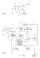
- the secondary circuit is composed of a coil (L2), arranged in parallel with a capacitor (C2), and a contact of the pushbutton type referenced (SW).
- the coil (L2) is electromagnetically coupled to the coil (L1) of the primary circuit, which is arranged in series with a capacitor (C1).
- the primary circuit is powered by two outputs (S1 and S2) whose voltages are in phase opposition. The frequency of these supplies substantially corresponds to the resonant frequency of the primary circuit, which is approximately double the resonant frequency of the secondary circuit.
- the components are chosen for this purpose.
- An alternating sinusoidal signal is taken between the coil (L1) and the capacitor (C1). Given the structure of the circuit, this signal is in phase quadrature with respect to the voltage of the outputs (S1 and S2).
- a high resistance (Ri), preferably greater than 10,000 ⁇ , is arranged between the sampling point of said intermediate signal and its input into the electronic processing circuit (E). As stated before, this resistance plays an important role in suppressing the amplitude factor in the measurement.
- a clipping device (D) located at the input of the circuit (E) allows the surplus to minimize the aspects of the signal related to the amplitude.
- FIG. 2 Downstream of the clipping device (D) is an edge detector circuit (14) which produces an output pulse at each rising or falling edge of the signal coming from the resistor (Ri), that is to say coming from the point common to the resonant circuit L1C1.
- the output of the edge detector circuit (14) is connected to one of the inputs of a phase comparator (15), the other input of which is connected to the generator supplying the primary circuit, the operation of which will be seen in more detail hereinafter in the text.
- the digital quantity obtained at the output of the phase comparator (15) corresponds to the temporary offset between the signal of the generator (13) and the signal of the point common to the circuit L1C1.
- This digital quantity constitutes a signal used to fulfill several functions in the circuit (E). Firstly, it adjusts the frequency of the voltages emitted by the power generator (13) after powering up the circuit (E).
- This generator (13) is simply a flip-flop, whose two outputs Q and Q ⁇ are respectively used for supplying one of the terminals of the coil (L1) and one of the terminals of the capacitor (C1).
- the change of state of the flip-flop is obtained via a binary counter (12) whose counting capacity is at least 8 bits, and which is connected to an oscillator (10) based on a quartz or a ceramic resonator (11). ) which guarantee the stability of the time base in the medium term.
- the counter is set in such a way that it provides each cycle with an excess signal C V of periodicity equal to half the signal delivered on the primary resonant circuit L1C1.
- the flip-flop (13) guarantees the provision of a signal perfectly symmetrical in duration at each change of state on the outputs S1 and S2, which therefore convey signals in phase opposition.
- phase comparator circuit (15) is sent to an initialization circuit (16) which adjusts, at the time of power-up, the counting capacity of the counter (12) to obtain a signal from the latch. a frequency approaching as close as possible the natural resonance frequency of the circuit L1 C1 associated by inductive coupling to the circuit L2C2.
- the state of the signal from the comparator (17) is analyzed by an analyzer stage (20), responsible for recalibrating the high and low reference levels, and for delivering an active state when the contact (SW) is closed.
- This stage is thus connected on the one hand to the initialization circuit (16), whose functions include adjustments and recalibrations, and on the other hand via another of its outputs, to an integrating filter (21) whose output is activated only after a certain amount of active states of valid measurement cycles has been measured.
- the integrable quantity can be parameterized from 2 to 250 cycles of oscillation of the generator (13).
- the output signal of the integrating filter (21) can be directly operated via a direct output (23).
- the output of the integrating filter (21) can be connected to a delay circuit (22), a delayed signal then being available at the output (24) of the processing circuit (E). This delay serves in particular to emit a pulse signal of fixed duration as soon as the contact (SW) is closed in the secondary circuit.
- the circuit (E) comprises according to a possibility a certain number of logic components based on synchronous or asynchronous elementary circuits. Alternatively, it may consist of a microprocessor or microcontroller, an essentially logical processing being made possible by the temporal nature of the measurement.
- One of the advantages of the circuit of the invention is that it allows a constant self-monitoring of the reliability of the measurements, as well as an adaptation of the supply frequencies and the threshold values according to the actual operating parameters, including the primary circuit.
- the circuit of the invention can be applied, in the automotive field, to the detection of the opening of a solid contact of a mobile part such as a rag (1). essentially consisting of a glazed surface which pivots with respect to a frame (2) of the vehicle frame.
- the contact (3) is in the circuit of the secondary coil (4), also attached to the hanger (1), while the primary coil (5) is fixed to the frame, as is the electronic circuit (6) for processing and the lock (7) electrically controlled.
- the coils (4, 5) are arranged such that when the rag (1) is closed, they are in an electromagnetic coupling situation. As already indicated, this coupling can be improved by means of a ferrite core fixed on the side of one or other of the coils (4, 5), or by means of two cores each equipping a coil ( 4, 5).
Landscapes
- Electronic Switches (AREA)
- Measurement Of Length, Angles, Or The Like Using Electric Or Magnetic Means (AREA)
Applications Claiming Priority (2)
| Application Number | Priority Date | Filing Date | Title |
|---|---|---|---|
| FR0110140 | 2001-07-27 | ||
| FR0110140A FR2828005B1 (fr) | 2001-07-27 | 2001-07-27 | Interrupteur a couplage inductif |
Publications (2)
| Publication Number | Publication Date |
|---|---|
| EP1280170A1 true EP1280170A1 (de) | 2003-01-29 |
| EP1280170B1 EP1280170B1 (de) | 2010-06-16 |
Family
ID=8866043
Family Applications (1)
| Application Number | Title | Priority Date | Filing Date |
|---|---|---|---|
| EP20020360225 Expired - Lifetime EP1280170B1 (de) | 2001-07-27 | 2002-07-26 | Schalter mit induktiver Kupplung |
Country Status (3)
| Country | Link |
|---|---|
| EP (1) | EP1280170B1 (de) |
| DE (1) | DE60236711D1 (de) |
| FR (1) | FR2828005B1 (de) |
Families Citing this family (2)
| Publication number | Priority date | Publication date | Assignee | Title |
|---|---|---|---|---|
| FR2948812B1 (fr) * | 2009-07-29 | 2011-08-19 | Leroy Automation | Dispositif actif de lecture de contact sec sous haute tension |
| FR2951313B1 (fr) * | 2009-10-12 | 2012-10-19 | Leroy Automation | Dispositif actif de lecture de contact sec sous haute tension |
Citations (3)
| Publication number | Priority date | Publication date | Assignee | Title |
|---|---|---|---|---|
| US4350971A (en) * | 1979-09-13 | 1982-09-21 | Lucas Industries Limited | Circuit for use in the detection of the condition of an isolated switch contact |
| US4556882A (en) * | 1982-11-15 | 1985-12-03 | Eaton Corporation | Remote control circuit breaker system with on-off-tripped-problem status storage and indication |
| EP0435686A2 (de) * | 1989-12-29 | 1991-07-03 | Kaye Instruments, Inc. | Kontaktsensormodul |
-
2001
- 2001-07-27 FR FR0110140A patent/FR2828005B1/fr not_active Expired - Fee Related
-
2002
- 2002-07-26 DE DE60236711T patent/DE60236711D1/de not_active Expired - Lifetime
- 2002-07-26 EP EP20020360225 patent/EP1280170B1/de not_active Expired - Lifetime
Patent Citations (3)
| Publication number | Priority date | Publication date | Assignee | Title |
|---|---|---|---|---|
| US4350971A (en) * | 1979-09-13 | 1982-09-21 | Lucas Industries Limited | Circuit for use in the detection of the condition of an isolated switch contact |
| US4556882A (en) * | 1982-11-15 | 1985-12-03 | Eaton Corporation | Remote control circuit breaker system with on-off-tripped-problem status storage and indication |
| EP0435686A2 (de) * | 1989-12-29 | 1991-07-03 | Kaye Instruments, Inc. | Kontaktsensormodul |
Also Published As
| Publication number | Publication date |
|---|---|
| FR2828005B1 (fr) | 2003-09-26 |
| EP1280170B1 (de) | 2010-06-16 |
| FR2828005A1 (fr) | 2003-01-31 |
| DE60236711D1 (de) | 2010-07-29 |
Similar Documents
| Publication | Publication Date | Title |
|---|---|---|
| FR3047808B1 (fr) | Procede de detection d'approche et/ou de contact d'une main d'un utilisateur vers une poignee de portiere de vehicule et dispositif de detection associe | |
| FR2624618A1 (fr) | Dispositif de mesure de valeurs electromagnetiques d'une bobine et, en particulier, de mesure de la position de l'armature d'un systeme magnetique a bobine/armature | |
| EP0918309B2 (de) | Verriegelungssystem für Kraftfahrzeuge mit Detektor zum Feststellen der Annäherung des Benutzers | |
| EP0522949A1 (de) | Annäherungsdetektor | |
| EP0762147A1 (de) | Universeller induktiver Näherungsschalter | |
| FR3067529B1 (fr) | Dispositif de tele-alimentation, de capteur de position et de communication sans fil pour une porte a poignee deployante de vehicule automobile | |
| EP3084962A2 (de) | Präsenzsensor für einen öffnungsfähigen karosserieabschnitt eines kraftfahrzeugs | |
| EP1280170B1 (de) | Schalter mit induktiver Kupplung | |
| FR3006793A1 (fr) | Dispositif, capteur et procede de detection de la presence d'un utilisateur pour l'ouverture d'un acces a un vehicule automobile | |
| EP1423917B1 (de) | Anwesenheitssensor | |
| FR2582880A1 (fr) | Dispositif de surveillance d'etat d'un commutateur electrique et relais electrique en comportant application | |
| FR2663751A1 (fr) | Magnetometre directionnel a resonance. | |
| WO2003050368A1 (fr) | Systeme de detection de presence d'un utilisateur notamment pour vehicule automobile | |
| CH690936A5 (fr) | Dispositif de détection ultra-sonore, notamment pour un système de nettoyage de pare-brise à commande automatique. | |
| EP0090689B1 (de) | Verfahren und Gerät zur Detektion eines magnetischen Stücks in einer definierten Nahzone | |
| WO1999062040A1 (fr) | Dispositif de detection de presence d'un corps humain | |
| WO2020048764A1 (fr) | Dispositif et procédé de détection d'intention de verrouillage ou de déverrouillage d'un ouvrant de véhicule automobile | |
| FR2722287A1 (fr) | Dispositif de detection d'objets. | |
| FR2927108A1 (fr) | Dispositif de detection de toucher d'une poignee de porte de vehicule automobile | |
| FR2785703A1 (fr) | Dispositif pour detecter la presence d'un individu et systeme de deverrouillage d'ouvrant(s) de vehicule, notamment automobile, comportant un tel dispositif | |
| FR2581200A1 (fr) | Dispositif de controle pour capteur de proximite. | |
| FR3046677B1 (fr) | Capteur, systeme et procede de detection de variation d'une capacite d'un condensateur de mesure | |
| FR2864377A1 (fr) | Boucle a asservissement de phase | |
| FR2998235A1 (fr) | Dispositif de detection d'un badge d'acces « main libre » autour d'un vehicule et de detection de presence d'un utilisateur a proximite d'un ouvrant d'un vehicule et procede de detection associe | |
| CH434774A (fr) | Dispositif pour mesurer l'intensité d'un champ magnétique faible, notamment du champ magnétique terrestre |
Legal Events
| Date | Code | Title | Description |
|---|---|---|---|
| PUAI | Public reference made under article 153(3) epc to a published international application that has entered the european phase |
Free format text: ORIGINAL CODE: 0009012 |
|
| 17P | Request for examination filed |
Effective date: 20021029 |
|
| AK | Designated contracting states |
Designated state(s): AT BE BG CH CY CZ DE DK EE ES FI FR GB GR IE IT LI LU MC NL PT SE SK TR |
|
| AX | Request for extension of the european patent |
Extension state: AL LT LV MK RO SI |
|
| AKX | Designation fees paid |
Designated state(s): DE FR |
|
| GRAP | Despatch of communication of intention to grant a patent |
Free format text: ORIGINAL CODE: EPIDOSNIGR1 |
|
| GRAS | Grant fee paid |
Free format text: ORIGINAL CODE: EPIDOSNIGR3 |
|
| GRAA | (expected) grant |
Free format text: ORIGINAL CODE: 0009210 |
|
| AK | Designated contracting states |
Kind code of ref document: B1 Designated state(s): DE FR |
|
| REF | Corresponds to: |
Ref document number: 60236711 Country of ref document: DE Date of ref document: 20100729 Kind code of ref document: P |
|
| PLBE | No opposition filed within time limit |
Free format text: ORIGINAL CODE: 0009261 |
|
| STAA | Information on the status of an ep patent application or granted ep patent |
Free format text: STATUS: NO OPPOSITION FILED WITHIN TIME LIMIT |
|
| 26N | No opposition filed |
Effective date: 20110317 |
|
| REG | Reference to a national code |
Ref country code: DE Ref legal event code: R097 Ref document number: 60236711 Country of ref document: DE Effective date: 20110316 |
|
| REG | Reference to a national code |
Ref country code: FR Ref legal event code: PLFP Year of fee payment: 15 |
|
| REG | Reference to a national code |
Ref country code: FR Ref legal event code: PLFP Year of fee payment: 16 |
|
| REG | Reference to a national code |
Ref country code: FR Ref legal event code: PLFP Year of fee payment: 17 |
|
| REG | Reference to a national code |
Ref country code: DE Ref legal event code: R082 Ref document number: 60236711 Country of ref document: DE Representative=s name: MANITZ FINSTERWALD PATENT- UND RECHTSANWALTSPA, DE Ref country code: DE Ref legal event code: R082 Ref document number: 60236711 Country of ref document: DE Representative=s name: MANITZ FINSTERWALD PATENTANWAELTE PARTMBB, DE Ref country code: DE Ref legal event code: R081 Ref document number: 60236711 Country of ref document: DE Owner name: APTIV TECHNOLOGIES LIMITED, BB Free format text: FORMER OWNER: DELPHI TECHNOLOGIES, INC., TROY, MICH., US |
|
| PGFP | Annual fee paid to national office [announced via postgrant information from national office to epo] |
Ref country code: FR Payment date: 20190726 Year of fee payment: 18 |
|
| PG25 | Lapsed in a contracting state [announced via postgrant information from national office to epo] |
Ref country code: FR Free format text: LAPSE BECAUSE OF NON-PAYMENT OF DUE FEES Effective date: 20200731 |
|
| PGFP | Annual fee paid to national office [announced via postgrant information from national office to epo] |
Ref country code: DE Payment date: 20210726 Year of fee payment: 20 |
|
| REG | Reference to a national code |
Ref country code: DE Ref legal event code: R071 Ref document number: 60236711 Country of ref document: DE |