EP1280672B1 - Eine erste stufe bildende trommel zur herstellung eines mit notlaufeigenschaften versehenen luftreifens und verfahren zu deren verwendung - Google Patents
Eine erste stufe bildende trommel zur herstellung eines mit notlaufeigenschaften versehenen luftreifens und verfahren zu deren verwendung Download PDFInfo
- Publication number
- EP1280672B1 EP1280672B1 EP01934983A EP01934983A EP1280672B1 EP 1280672 B1 EP1280672 B1 EP 1280672B1 EP 01934983 A EP01934983 A EP 01934983A EP 01934983 A EP01934983 A EP 01934983A EP 1280672 B1 EP1280672 B1 EP 1280672B1
- Authority
- EP
- European Patent Office
- Prior art keywords
- spacer
- drum
- pair
- tire
- receiving
- Prior art date
- Legal status (The legal status is an assumption and is not a legal conclusion. Google has not performed a legal analysis and makes no representation as to the accuracy of the status listed.)
- Expired - Lifetime
Links
Images


Classifications
-
- B—PERFORMING OPERATIONS; TRANSPORTING
- B29—WORKING OF PLASTICS; WORKING OF SUBSTANCES IN A PLASTIC STATE IN GENERAL
- B29D—PRODUCING PARTICULAR ARTICLES FROM PLASTICS OR FROM SUBSTANCES IN A PLASTIC STATE
- B29D30/00—Producing pneumatic or solid tyres or parts thereof
- B29D30/06—Pneumatic tyres or parts thereof (e.g. produced by casting, moulding, compression moulding, injection moulding, centrifugal casting)
- B29D30/08—Building tyres
- B29D30/20—Building tyres by the flat-tyre method, i.e. building on cylindrical drums
- B29D30/24—Drums
- B29D30/244—Drums for manufacturing substantially cylindrical tyre components with cores or beads, e.g. carcasses
- B29D30/246—Drums for the multiple stage building process, i.e. the building-up of the cylindrical carcass is realised on one drum and the toroidal expansion is realised after transferring on another drum
-
- B—PERFORMING OPERATIONS; TRANSPORTING
- B29—WORKING OF PLASTICS; WORKING OF SUBSTANCES IN A PLASTIC STATE IN GENERAL
- B29D—PRODUCING PARTICULAR ARTICLES FROM PLASTICS OR FROM SUBSTANCES IN A PLASTIC STATE
- B29D30/00—Producing pneumatic or solid tyres or parts thereof
- B29D30/06—Pneumatic tyres or parts thereof (e.g. produced by casting, moulding, compression moulding, injection moulding, centrifugal casting)
- B29D30/08—Building tyres
- B29D30/20—Building tyres by the flat-tyre method, i.e. building on cylindrical drums
- B29D2030/201—Manufacturing run-flat tyres
Definitions
- the invention relates to a tire building drum and a method of building a body ply carcass for a run flat tire according to the preamble of claim 1 and of claim 11 respectively.
- Such a drum and method are known from the WO 9854008-A.
- the present invention provides a first stage run flat tire building drum and method using a spacer or sleeve mounted on the center of a usual tire building drum, wherein the spacer has a width the same as the distance between the inside edges of the inbound and outbound sidewall rubber inserts of a run flat tire and a height equal to that of the rubber insert at its thickest point.
- the tire building drum of the present invention enables the building of a uniform first stage tire carcass free of interruptions from the sidewall inserts and which provides a relatively smooth body contour for receiving the other tire components.
- the tire building drum of the invention enables the innerliner to be placed radially inwardly or outwardly of the sidewall inserts without changing the structure of the tire building drum and without special assembly procedures.
- Another aspect of the invention includes forming the spacer sleeve in same number of arcuate segments as is the expandable tire building drum so as to be compatible therewith, and in which the spacer segments can be formed of a rigid, lightweight material such as polyurethane.
- Another feature of the invention is to provide building the first stage body ply without trapping air between the plies and inserts and without bumps or protrusions being formed thereby.
- a further advantage of the invention is to enable a usual first stage tire building drum to be usable for building various sizes of run flat tires, having various size sidewall inserts, by changing the axial length and height of the spacer sleeve placed on the tire building drum, and without changing the method of manufacture of the first stage body ply carcass.
- Fig. 1 is a generally diagrammatic view of a usual prior art first stage tire building drum indicated generally at 1.
- Drum 1 is formed by a plurality of arcuate segments 2, six of which are shown for the particular construction of drum 1 of Fig. 1, which are connected by various well known types of linkage means (not shown), which enable the segments to be expanded outwardly from the contracted position of Fig. 1 to an expandable position as shown in Fig. 2.
- linkage means not shown
- the particular construction of the drum segments, linkages and expansion mechanisms, as well as the bead ring clamping mechanism, are well known in the art and thus are not further described in detail.
- Prior art examples of tire building drums in which the present invention can be incorporated are shown in U.S. Patent No. 4,402,783; 5,591,288; 4,229,246; 3,915,788; 4,108,707; 4,278,484; and 5,308,384.
- Drum 5 is similar to prior art drum 1 discussed above, in that it has a plurality of the same expandable segments 2 and is rotated by a usual shaft 6, and has an appropriate expansion mechanism and linkages, as shown diagrammatically by rod 3 and connector block 4 (Fig. 5), for expanding the drum from the contracted position of Fig. 1 to an expanded position shown in Fig. 2.
- spacer 7 is located at the centerline 8 of the building drum.
- spacer 7 is comprised of six, preferably equal arcuate segments 8, which collectively form spacer 7.
- Segments 8 can be formed of various metals or of a plastic material such as a polyurethane, enabling the same to be easily machined or molded.
- Segments 8 can be fixed onto the plurality of drum segments 2 which collectively form a smooth, cylindrical central portion 10 of the drum, by various types of fasteners such as bolts 9 (Fig. 5), or by an adhesive or other type of fasteners, in order to be in a fixed position on each of the arcuate segments 2.
- Each arcuate segment 8 includes a smooth, curved outer surface 11 which terminates in a pair of tapered arcuate edges 12.
- Spacer 7, and in particular, arcuate segments 8, will have a height T (Fig. 5), which will be generally equal to the maximum thickness of elastomeric sidewall inserts 15 as shown particularly in Figs. 3, 4 and 6.
- the axial length or width W of spacer 7 will be the distance D (Figs. 7 and 8) between the inside edges 16 of the inboard and outboard sidewall inserts 15 when incorporated into the sidewalls 18 of a usual pneumatic tire 20.
- spacer 7 forms a pair of adjacent cylindrical recessed areas 22 extending about drum 5 having a depth equal to height T of spacer 7.
- Fig. 3 shows the use of drum 5 to form a first stage tire carcass.
- a pair of sidewall inserts 15 are placed in recessed areas 22 and extend axially therealong from tapered edges 12 and circumferentially about the drum. inserts 15 form the pair of spaced crescent-shaped annular sidewall reinforcement in the final tire as shown in Figs. 7 and 8.
- an air impervious innerliner 23 is placed in the usual manner about the drum and will extend generally along a predetermined axial length of the drum.
- a first body ply 24, which will usually contain reinforcing cords, is placed about innerliner 23. Additional body plies can be placed over innerliner 23 if desired, although, only one is shown in Figs. 3 and 4.
- bead rings 25 will be moved axially inward along and about drum 5, ultimately being positioned above U-shaped annular grooves 26 which form bead receiving recesses.
- the drum segments are expanded outwardly as shown by arrows A Fig. 4 bringing the components into tight engagement with each other and securely trapping beads rings 25 within grooves 26, as shown particularly in Fig. 4.
- top surfaces 28 of elastomeric inserts 15 lie in a substantially flat common plane when viewed in cross section, with the smooth top surface 11 of spacer 7. This provides for a relatively smooth, continuous, flat annular surface extending about the drum between bead rings 25 which prevents the formation of spaces between the various components and in particular with the sidewall inserts which heretofore trapped air which cause problems during vulcanization.
- the outer ends 29 and 30 of innerliner 23 and body ply 24 respectively, are then turned up about bead rings 25 in a well known tire forming operation.
- the drum is then retracted to a collapsed position and this first body ply carcass indicated at 32, is then removed from the drum for-further incorporation into a final tire construction at a second stage tire building drum.
- first body ply carcass 32 the main difference from a usual tire building procedure is the placement of inserts 15 in recessed areas 22 which provides the generally smooth, continuous, flat body ply layup surface extending along the majority of the axial drum length and circumferentially about the drum.
- Fig. 6 shows a slightly modified method of forming a first stage body ply carcass which involves placing innerliner 23 on the drum building surface prior to the placement of elastomeric inserts 15 in recessed areas 22.
- the thickness of innerliner 23 is so slight that is still enables the top surfaces 28 of inserts 15 to form the generally flat, continuous body ply layup surface throughout the majority of the axial length of drum 5.
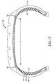
- Figs. 7 and 8 diagrammatically show run flat tires 20 produced by the body ply carcasses formed in Figs. 3-4 and 6 respectively.
- the length of elastomeric inserts 15 is chosen so as to extend generally from the shoulder area of the tire to adjacent the bead area and with the distance D between the inboard ends 16 of sidewall inserts 15, being equal to the axial length of spacer 7.
- spacer 7 which can be mounted or affixed in various manners at the center of cylindrical portion 10 of a usual expandable tire building drum, provides for a pair of adjacent recessed areas for receiving the pair of elastomeric inserts which will form the crescent shaped sidewall inserts of a run flat tire.
- Spacer 7, in combination with the outer surface of inserts 15, provide for a generally smooth, continuous ply receiving surface extending throughout the majority of the axial length of the tire building drum and circumferentially thereabout, which will property space the sidewall inserts by the selected axial length of spacer 7, as well as the desired thickness of the sidewall inserts, which will be approximately equal to the height T of spacer 7. All of this can be accomplished relatively easily and inexpensively by forming spacer 7 from a plurality of arcuate segments which are attached by various types of fastening means to each of the individual segments 2 of a usual expandable segmented tire building drum.
Landscapes
- Engineering & Computer Science (AREA)
- Manufacturing & Machinery (AREA)
- Mechanical Engineering (AREA)
- Tyre Moulding (AREA)
- Tires In General (AREA)
Claims (16)
- Reifenaufbautrommel (5), die einen zylindrischen mittigen Teil besitzt, der durch eine Vielzahl nach außen expandierbarer Segmente (2) und ein Paar Wulst aufnehmender Bereiche gebildet wird, die an den mittigem Teil zum aufnehmen der Wulstringe (25) darauf nach außen gerichteter Expansion der Segmente (2) gebildet wird, wobei ein ringförmiges Abstandsstück (7) auf dem mittigen Teil der Trommel (5) befestigt ist und eine im wesentlichen glatte zylindrische Außenfläche (11) mit einem größeren Radius als ein Radius des zylindrischen mittigen Teils (10) der Trommel (5) besitzt und ein Paar beabstandeter ringförmiger ausgesparter Bereiche (22) angrenzend an das Abstandsstück (7) besitzt, um ein Paar elastomerer Einsätze (15) darauf aufzunehmen, wobei das ringförmige Abstandsstück (7) durch eine Vielzahl nach außen expandierbarer bogenförmiger Segmente (8) gebildet wird.
- Reifenaufbautrommel nach Anspruch 1, bei der jeder Wulst aufnehmende Bereich eine generell U-förmige Ausnehmung (26) darstellt, die in den Segmenten (8) ausgebildet ist.
- Reifenaufbautrommel nach Anspruch 1, bei dem jedes nach außen expandierbares Abstandsstück (7) zugespitzte Kanten (12) besitzt.
- Reifenaufbautrommel nach Anspruch 1, einschließlich einer Welle (6) zum Drehen der Trommel (5).
- Kombination einer Vielzahl von Reifenkomponenten, einschließlich eines Paares elastomerer Einsätze (15), eines Innerliners oder Futters (23) und mindestens einer Unterbaulage (24) zum Ausbilden einer erststufigen Reifenkarkasse (32) für einen Notlaufreifen, und eine Reifenaufbautrommel (5) nach Anspruch 1, wobei die Trommel (5) ein mittiges ringförmiges Abstandsstück (7) umfaßt, das eine glatte zylindrische Außenfläche (11) und ein Paar ausgesparter Flächen (22) angrenzend an das Abstandsstück (7) besitzt, wobei das Abstandsstück (7) eine Höhe besitzt, die im wesentlichen der Dicke der elastomeren Einsätze (15) gleicht, die auf den ausgesparten Flächen (22) befestigt sind, wobei die Einsätze (15) im wesentlichen glatte Außenflächen besitzen, die generell zu der Außenfläche des Abstandsstücks (7) ausgerichtet sind, um eine generell glatte kontinuierliche zylindrische Lagenauflegefläche zum Aufnehmen mindestens der Unterbaulage (24) darauf vorzusehen.
- Kombination nach Anspruch 5, einschließlich eines Paares von Wulst (25) aufnehmenden Nuten (26), die in der Reifenaufbautrommel (5) außerhalb der ausgesparten Flächen (22) zum Aufnehmen der Wulste darin ausgebildet sind.
- Kombination nach Anspruch 5, bei der der Innerliner zwischen der Unterbaulage (24) und der Lagenauflegefläche angeordnet ist, die durch die Außenfläche der elastomeren Einsätze (15) und der Außenfläche des mittigen Abstandsstücks (7) ausgebildet wird.
- Kombination nach Anspruch 5, bei der das mittige Abstandsstück in einem Paar nach unten und außen sich zuspitzender Endkanten endet.
- Kombination nach Anspruch 5, bei der der Innerliner zwischen den elastomeren Einsätzen (15) und dem beabstandeten Paar ausgesparter Trommelflächen angeordnet ist.
- Kombination nach Anspruch 5, bei der die Trommel (5) eine Vielzahl bogenförmiger Segmente (8) umfaßt.
- Verfahren zum Aufbauen einer Unterbaulagenkarkasse (32) für einen Notlaufreifen, einschließlich folgender Stufen:Vorsehen einer expandierbaren Reifenaufbautrommel (5), die ein ringförmiges Abstandsstück (7) besitzt, das eine glatte mittige äußere Zylinderfläche und ein Paar angrenzender ausgesparter Einsatz aufnehmender Bereiche angrenzend an das Abstandsstück (7) und ein Paar äußerer Wulst aufnehmender Bereiche besitzt,Einsetzen eines elastomeren Einsatzes (15), die jeweils einer generell glatte Außenfläche in jeder der ausgesparten Einsatz aufnehmenden Bereiche besitzen, wodurch die mittige äußere Zylinderfläche des Abstandsstücks und die Außenfläche des Einsatzpaares eine generell glatte kontinuierliche Lagen aufnehmende Fläche bilden, Einsetzen des Innerliners (23) über das Abstandsstück (7), die Einsatz aufnehmenden Bereiche und die Wulst aufnehmenden Bereiche,Einsetzen einer Unterbaulage (24) über den Innerliner (23) und die Lagen aufnehmende Fläche unter Ausbildung einer generell geraden glatten Unterbaulagenkarkasse (32), undEinsetzen eines Ringwulstes in jeden der Wulst aufnehmenden Bereiche auf einer Reifenaufbautrommel nach Anspruch 1.
- Verfahren nach Anspruch 11, einschließlich der Stufe des Einsetzens des Innerliners (23) direkt in Kontakt mit der Lagen aufnehmenden Fläche.
- Verfahren nach Anspruch 11, einschließlich der Stufe des Einsetzens des Innerliners zwischen die elastomeren Einsätze (15) und die ausgesparten Einsatz aufnehmenden Bereiche der Trommel (5).
- Verfahren nach Anspruch 11, einschließlich der Stufe des Vorsehens des Abstandsstücks (7) mit einer radialen Höhe, die im wesentlichen der maximalen Dicke des elastomeren Einsatzes (15) gleicht.
- Verfahren nach Anspruch 11, einschließlich der Stufe des Vorsehens des Abstandsstücks (7) mit einer axialen Breite, die im wesentlichen der Entfernung zwischen den Innenkanten der elastomeren Einsätze (15) gleicht.
- Verfahren nach Anspruch 11, einschließlich der Stufe des Expandierens der Trommel (5) radial nach außen, um die Wulste in den Wulst aufnehmenden Bereichen zu befestigen.
Applications Claiming Priority (3)
| Application Number | Priority Date | Filing Date | Title |
|---|---|---|---|
| US09/570,083 US6488797B1 (en) | 2000-05-12 | 2000-05-12 | First stage run flat tire building drum and method of using same |
| US570083 | 2000-05-12 | ||
| PCT/US2001/014111 WO2001085475A1 (en) | 2000-05-12 | 2001-05-02 | First stage building drum for manufacturing run-flat tyres and method of using the same |
Publications (2)
| Publication Number | Publication Date |
|---|---|
| EP1280672A1 EP1280672A1 (de) | 2003-02-05 |
| EP1280672B1 true EP1280672B1 (de) | 2004-03-17 |
Family
ID=24278147
Family Applications (1)
| Application Number | Title | Priority Date | Filing Date |
|---|---|---|---|
| EP01934983A Expired - Lifetime EP1280672B1 (de) | 2000-05-12 | 2001-05-02 | Eine erste stufe bildende trommel zur herstellung eines mit notlaufeigenschaften versehenen luftreifens und verfahren zu deren verwendung |
Country Status (5)
| Country | Link |
|---|---|
| US (1) | US6488797B1 (de) |
| EP (1) | EP1280672B1 (de) |
| JP (1) | JP4777585B2 (de) |
| DE (1) | DE60102370T2 (de) |
| WO (1) | WO2001085475A1 (de) |
Families Citing this family (23)
| Publication number | Priority date | Publication date | Assignee | Title |
|---|---|---|---|---|
| JP4603736B2 (ja) * | 2001-09-06 | 2010-12-22 | 株式会社ブリヂストン | タイヤの製造方法 |
| TW564226B (en) * | 2003-02-18 | 2003-12-01 | Shuei-Jen Shiu | Enhanced method for manufacturing anti-puncturing tires |
| DE102004008273B4 (de) * | 2004-02-20 | 2012-09-20 | Continental Reifen Deutschland Gmbh | Vorrichtung zum Konfektionieren von Reifenbauteilen und Verfahren zu deren Betrieb |
| RU2337823C2 (ru) * | 2004-04-30 | 2008-11-10 | Пирелли Тайр С.П.А. | Способ и устройство для изготовления шины, способной обеспечивать движение в спущенном состоянии, для колес транспортных средств |
| WO2005105419A1 (en) * | 2004-04-30 | 2005-11-10 | Pirelli Tyre S.P.A. | Method and apparatus for manufacturing a run-flat tyre for vehicle wheels |
| JP4277826B2 (ja) * | 2005-06-23 | 2009-06-10 | 住友電気工業株式会社 | 窒化物結晶、窒化物結晶基板、エピ層付窒化物結晶基板、ならびに半導体デバイスおよびその製造方法 |
| JP4962833B2 (ja) * | 2005-11-30 | 2012-06-27 | 横浜ゴム株式会社 | 成形ドラム |
| DE602005023916D1 (de) | 2005-12-28 | 2010-11-11 | Pirelli | Verfahren und vorrichtung zur herstellung von luftreifen |
| FR2900093B1 (fr) * | 2006-04-21 | 2008-07-04 | Michelin Soc Tech | Perfectionnement d'un tambour d'assemblage destine a la fabrication des pneumatiques autoporteurs. |
| JP4757699B2 (ja) * | 2006-04-24 | 2011-08-24 | 株式会社ブリヂストン | 空気入りタイヤの製造方法および空気入りタイヤ |
| JP4616905B2 (ja) * | 2008-08-26 | 2011-01-19 | 住友ゴム工業株式会社 | 成形ドラム装置及びそれを用いたランフラットタイヤの製造方法 |
| RU2478483C1 (ru) * | 2011-11-08 | 2013-04-10 | Виктор Васильевич Калинин | Способ регулирования силы трения колес транспортного средства на камерах-шинах |
| US9908302B2 (en) * | 2012-06-21 | 2018-03-06 | Compagnie Generale Des Etablissements Michelin | Method for adhering an innerliner to a carcass ply of a tire |
| JP6153845B2 (ja) * | 2013-10-25 | 2017-06-28 | 東洋ゴム工業株式会社 | タイヤ成型ドラム用スリーブ、タイヤ成型装置、及びタイヤ成型方法 |
| RU2548995C1 (ru) * | 2014-01-09 | 2015-04-20 | Виктор Васильевич Калинин | Способ регулирования силы трения колес транспортного средства на камерах-шинах |
| WO2016130347A1 (en) | 2015-02-11 | 2016-08-18 | Bridgestone Americas Tire Operations, Llc | A runflat tire with sidewall-reinforcing inserts |
| EP3541640B1 (de) | 2016-11-17 | 2022-08-24 | Bridgestone Americas Tire Operations, LLC | Luftreifen mit an eine luftsperrschicht angehaftetes dämpfungselement |
| DE102017214675A1 (de) | 2017-08-22 | 2019-02-28 | Continental Reifen Deutschland Gmbh | Verfahren zur Herstellung eines Fahrzeugluftreifens mit Notlaufeigenschaften |
| JP6993874B2 (ja) * | 2017-12-28 | 2022-01-14 | Toyo Tire株式会社 | シート部材の巻き取り方法及び巻き取り筒 |
| KR102053736B1 (ko) * | 2018-11-20 | 2019-12-09 | 문형철 | 런플랫 타이어의 사이드월인서트 성형드럼 장치 및 이것을 이용한 런플랫 타이어 조립 방법 |
| CN113840877A (zh) | 2019-04-29 | 2021-12-24 | 株式会社普利司通 | 用于充气轮胎的侧壁支撑件 |
| NL2024329B1 (en) * | 2019-11-28 | 2021-08-31 | Vmi Holland Bv | Transfer wheel, transfer device and method for transferring a strip to a tire building drum |
| CN111002611B (zh) * | 2019-12-26 | 2025-03-07 | 山东宏盛橡胶科技有限公司 | 一种缺气保用成型鼓 |
Family Cites Families (32)
| Publication number | Priority date | Publication date | Assignee | Title |
|---|---|---|---|---|
| DE166792C (de) | ||||
| US607991A (en) | 1898-07-26 | guthrie | ||
| FR1311160A (fr) | 1961-06-15 | 1962-12-07 | Dunlop Sa | Machine à replier sur eux-mêmes des manchons en matières souples telles que des tissus gommés |
| US3402090A (en) | 1965-05-14 | 1968-09-17 | Gen Tire & Rubber Co | Tire shaping apparatus |
| US3556891A (en) | 1969-04-21 | 1971-01-19 | Uniroyal Inc | Pneumatic tire method of fabrication and intermediate article |
| US3813271A (en) | 1972-06-28 | 1974-05-28 | Goodyear Tire & Rubber | Belt building drum |
| JPS5116074B2 (de) | 1972-11-09 | 1976-05-21 | ||
| CA1062594A (en) | 1974-05-22 | 1979-09-18 | Frank R. Jellison | Building machine having an infinite number of drum settings |
| US3963394A (en) | 1975-06-25 | 1976-06-15 | Uniroyal Inc. | Bladder for shaping pneumatic tire |
| US4052237A (en) | 1976-01-05 | 1977-10-04 | The Goodyear Tire & Rubber Company | Closed torus tire |
| FR2347216A1 (fr) | 1976-04-08 | 1977-11-04 | Wolber | Boyau pour cycle et son procede de fabrication |
| US4152191A (en) | 1977-10-11 | 1979-05-01 | The Goodyear Tire & Rubber Company | Curing a replaceable tread for a big tire |
| JPS5463184A (en) * | 1977-10-28 | 1979-05-21 | Bridgestone Tire Co Ltd | Tire forming drum |
| US4229246A (en) | 1978-12-18 | 1980-10-21 | The Steelastic Company | Building drum assembly |
| US4263083A (en) | 1979-07-20 | 1981-04-21 | The Goodyear Tire & Rubber Company | Building and curing an inextensible belt structure for a tire assembly |
| US4278484A (en) | 1979-12-26 | 1981-07-14 | Mccreary Tire & Rubber Company | Pneumatic side wall bonding in radial tire manufacture |
| US4325764A (en) | 1980-06-19 | 1982-04-20 | The Goodyear Tire & Rubber Company | Drum and method of shaping a radial tire |
| JPS57174236A (en) | 1981-04-20 | 1982-10-26 | Mitsubishi Heavy Ind Ltd | Feeder for tire molding machine |
| US4402783A (en) | 1981-04-30 | 1983-09-06 | Nrm Corporation | Axially collapsible and expandable tire building drum |
| JPS5912834A (ja) | 1982-07-13 | 1984-01-23 | Bridgestone Corp | ラジアルタイヤ成形機用成形ドラム |
| US4510002A (en) | 1982-11-02 | 1985-04-09 | W & A Bates Limited | Manufacture of pneumatic tires |
| US4859272A (en) | 1988-06-22 | 1989-08-22 | The Goodyear Tire & Rubber Company | Radial tire belt folding drum |
| JPH03101922A (ja) | 1989-09-18 | 1991-04-26 | Bridgestone Corp | タイヤの製造方法 |
| US5268057A (en) | 1989-12-14 | 1993-12-07 | Sumitomo Rubber Industries Ltd. | Tire building apparatus |
| JPH0644674Y2 (ja) | 1990-03-30 | 1994-11-16 | 住友ゴム工業株式会社 | フォーマー |
| SU1717402A2 (ru) | 1990-07-09 | 1992-03-07 | Научно-исследовательский институт крупногабаритных шин | Барабан дл сборки покрышек пневматических шин |
| US5116449A (en) | 1990-09-04 | 1992-05-26 | The Uniroyal Goodrich Tire Company | Grooved drum for tire building machine |
| RU2011534C1 (ru) | 1992-07-16 | 1994-04-30 | Научно-исследовательский институт крупногабаритных шин | Устройство для сборки и формования покрышек пневматических шин |
| ES2117207T3 (es) | 1993-03-04 | 1998-08-01 | Bridgestone Corp | Metodo para la fabricacion de neumaticos sin vulcanizar. |
| CA2121159C (en) * | 1993-07-16 | 2005-03-29 | Kenneth Dean Conger | Contoured tire building drum and method of building an extended mobility tire |
| US5795416A (en) | 1996-08-02 | 1998-08-18 | Michelin Recherche Et Technique | Run-flat tire having partial carcass layers |
| ATE218449T1 (de) | 1997-05-29 | 2002-06-15 | Goodyear Tire & Rubber | Reifen mit einer gürtelverbundstruktur und verfahren zur herstellung |
-
2000
- 2000-05-12 US US09/570,083 patent/US6488797B1/en not_active Expired - Lifetime
-
2001
- 2001-05-02 JP JP2001582105A patent/JP4777585B2/ja not_active Expired - Fee Related
- 2001-05-02 DE DE60102370T patent/DE60102370T2/de not_active Expired - Lifetime
- 2001-05-02 EP EP01934983A patent/EP1280672B1/de not_active Expired - Lifetime
- 2001-05-02 WO PCT/US2001/014111 patent/WO2001085475A1/en not_active Ceased
Also Published As
| Publication number | Publication date |
|---|---|
| JP4777585B2 (ja) | 2011-09-21 |
| DE60102370T2 (de) | 2004-07-29 |
| EP1280672A1 (de) | 2003-02-05 |
| WO2001085475A8 (en) | 2001-12-13 |
| WO2001085475A1 (en) | 2001-11-15 |
| DE60102370D1 (de) | 2004-04-22 |
| US6488797B1 (en) | 2002-12-03 |
| JP2003532566A (ja) | 2003-11-05 |
Similar Documents
| Publication | Publication Date | Title |
|---|---|---|
| EP1280672B1 (de) | Eine erste stufe bildende trommel zur herstellung eines mit notlaufeigenschaften versehenen luftreifens und verfahren zu deren verwendung | |
| CA2121159C (en) | Contoured tire building drum and method of building an extended mobility tire | |
| KR20040041052A (ko) | 환형의 탄성중합체 타이어 콤포넌트의 형성 방법 | |
| US6123132A (en) | Tire with shoulders having a ply support strip between carcass and inner liner | |
| US20020157753A1 (en) | Self-supporting tyre for vehicle wheels, and method for manufacturing the same | |
| JP2003237314A (ja) | クラウン強化のためのアンダーレイ構造 | |
| EP1429928B1 (de) | Notlaufreifen für fahrzeugräder, und verfahren zur herstellung desselben | |
| EP0053997B1 (de) | Luftreifen und Verfahren zu seiner Herstellung | |
| JP2003094913A (ja) | 冬用ランフラットタイヤ及びその製造方法 | |
| EP1543999B1 (de) | Reifen mit tiefer Laufflächenrille in der ein undehnbarer Ring angeordnet ist | |
| JPH08230072A (ja) | トラック、バス用の更生タイヤの製造方法 | |
| JP3735447B2 (ja) | 空気入りタイヤ | |
| EP0317318B1 (de) | Verfahren zur Herstellung von Reifen | |
| CA1110957A (en) | Closed tube simplified radial tire, tire/rim assembly and method of making same | |
| JP3726085B2 (ja) | 建設車両用ラジアルタイヤの製造方法 | |
| JP3124931B2 (ja) | ラジアルタイヤの製造方法 | |
| EP0894614B1 (de) | Verfahren zur Herstellung eines Luftreifens für Fahrzeugräder | |
| EP1525105A1 (de) | Fahrzeugradreifen mit verstärktem wulst | |
| JP2005212278A (ja) | タイヤの製造方法 | |
| EP0047711A2 (de) | Erneuerung von Radialreifen | |
| JP3051456B2 (ja) | 空気入りラジアルタイヤの更生方法 | |
| EP0894645B1 (de) | Luftreifen für Fahrzeugräder und Felge verwendet in Kombination mit diesem Reifen | |
| JP2026510389A (ja) | 非空気式タイヤ用のトレッドバンド組立体を硬化させるためのシステム及び方法 | |
| CN120882570A (zh) | 成型用于轮胎的带组件的系统和方法 | |
| JPH04216035A (ja) | 空気入りラジアルタイヤの更生方法 |
Legal Events
| Date | Code | Title | Description |
|---|---|---|---|
| PUAI | Public reference made under article 153(3) epc to a published international application that has entered the european phase |
Free format text: ORIGINAL CODE: 0009012 |
|
| 17P | Request for examination filed |
Effective date: 20021016 |
|
| AK | Designated contracting states |
Designated state(s): AT BE CH CY DE DK ES FI FR GB GR IE IT LI LU MC NL PT SE TR |
|
| AX | Request for extension of the european patent |
Extension state: AL LT LV MK RO SI |
|
| 17Q | First examination report despatched |
Effective date: 20030313 |
|
| GRAP | Despatch of communication of intention to grant a patent |
Free format text: ORIGINAL CODE: EPIDOSNIGR1 |
|
| GRAS | Grant fee paid |
Free format text: ORIGINAL CODE: EPIDOSNIGR3 |
|
| GRAA | (expected) grant |
Free format text: ORIGINAL CODE: 0009210 |
|
| AK | Designated contracting states |
Kind code of ref document: B1 Designated state(s): DE FR GB IT LU |
|
| REG | Reference to a national code |
Ref country code: GB Ref legal event code: FG4D |
|
| REG | Reference to a national code |
Ref country code: IE Ref legal event code: FG4D |
|
| REF | Corresponds to: |
Ref document number: 60102370 Country of ref document: DE Date of ref document: 20040422 Kind code of ref document: P |
|
| LTIE | Lt: invalidation of european patent or patent extension |
Effective date: 20040317 |
|
| ET | Fr: translation filed | ||
| PLBE | No opposition filed within time limit |
Free format text: ORIGINAL CODE: 0009261 |
|
| STAA | Information on the status of an ep patent application or granted ep patent |
Free format text: STATUS: NO OPPOSITION FILED WITHIN TIME LIMIT |
|
| REG | Reference to a national code |
Ref country code: IE Ref legal event code: MM4A |
|
| 26N | No opposition filed |
Effective date: 20041220 |
|
| PGFP | Annual fee paid to national office [announced via postgrant information from national office to epo] |
Ref country code: GB Payment date: 20140425 Year of fee payment: 14 |
|
| GBPC | Gb: european patent ceased through non-payment of renewal fee |
Effective date: 20150502 |
|
| REG | Reference to a national code |
Ref country code: FR Ref legal event code: PLFP Year of fee payment: 16 |
|
| PG25 | Lapsed in a contracting state [announced via postgrant information from national office to epo] |
Ref country code: GB Free format text: LAPSE BECAUSE OF NON-PAYMENT OF DUE FEES Effective date: 20150502 |
|
| PGFP | Annual fee paid to national office [announced via postgrant information from national office to epo] |
Ref country code: LU Payment date: 20160518 Year of fee payment: 16 |
|
| PGFP | Annual fee paid to national office [announced via postgrant information from national office to epo] |
Ref country code: DE Payment date: 20160524 Year of fee payment: 16 |
|
| PGFP | Annual fee paid to national office [announced via postgrant information from national office to epo] |
Ref country code: FR Payment date: 20160428 Year of fee payment: 16 Ref country code: IT Payment date: 20160517 Year of fee payment: 16 |
|
| PG25 | Lapsed in a contracting state [announced via postgrant information from national office to epo] |
Ref country code: LU Free format text: LAPSE BECAUSE OF NON-PAYMENT OF DUE FEES Effective date: 20170531 |
|
| REG | Reference to a national code |
Ref country code: DE Ref legal event code: R119 Ref document number: 60102370 Country of ref document: DE |
|
| REG | Reference to a national code |
Ref country code: FR Ref legal event code: ST Effective date: 20180131 |
|
| PG25 | Lapsed in a contracting state [announced via postgrant information from national office to epo] |
Ref country code: LU Free format text: LAPSE BECAUSE OF NON-PAYMENT OF DUE FEES Effective date: 20170502 |
|
| PG25 | Lapsed in a contracting state [announced via postgrant information from national office to epo] |
Ref country code: DE Free format text: LAPSE BECAUSE OF NON-PAYMENT OF DUE FEES Effective date: 20171201 |
|
| PG25 | Lapsed in a contracting state [announced via postgrant information from national office to epo] |
Ref country code: IT Free format text: LAPSE BECAUSE OF NON-PAYMENT OF DUE FEES Effective date: 20170502 Ref country code: FR Free format text: LAPSE BECAUSE OF NON-PAYMENT OF DUE FEES Effective date: 20170531 |