EP1280687B1 - Dispositif de positionnement sans contact pour baie de lavage automatique de vehicule - Google Patents
Dispositif de positionnement sans contact pour baie de lavage automatique de vehicule Download PDFInfo
- Publication number
- EP1280687B1 EP1280687B1 EP01931056A EP01931056A EP1280687B1 EP 1280687 B1 EP1280687 B1 EP 1280687B1 EP 01931056 A EP01931056 A EP 01931056A EP 01931056 A EP01931056 A EP 01931056A EP 1280687 B1 EP1280687 B1 EP 1280687B1
- Authority
- EP
- European Patent Office
- Prior art keywords
- vehicle
- sensor
- control unit
- overhead
- wash
- Prior art date
- Legal status (The legal status is an assumption and is not a legal conclusion. Google has not performed a legal analysis and makes no representation as to the accuracy of the status listed.)
- Expired - Lifetime
Links
- 239000007921 spray Substances 0.000 claims description 44
- 238000000034 method Methods 0.000 claims description 24
- 238000005259 measurement Methods 0.000 claims description 10
- 238000005406 washing Methods 0.000 claims description 8
- 230000011664 signaling Effects 0.000 claims 2
- 230000008878 coupling Effects 0.000 claims 1
- 238000010168 coupling process Methods 0.000 claims 1
- 238000005859 coupling reaction Methods 0.000 claims 1
- 239000000344 soap Substances 0.000 description 6
- XLYOFNOQVPJJNP-UHFFFAOYSA-N water Substances O XLYOFNOQVPJJNP-UHFFFAOYSA-N 0.000 description 6
- 230000008030 elimination Effects 0.000 description 3
- 238000003379 elimination reaction Methods 0.000 description 3
- 208000019901 Anxiety disease Diseases 0.000 description 2
- 230000036506 anxiety Effects 0.000 description 2
- 238000004140 cleaning Methods 0.000 description 1
- 230000000977 initiatory effect Effects 0.000 description 1
- 238000009434 installation Methods 0.000 description 1
- 238000012423 maintenance Methods 0.000 description 1
- 238000004519 manufacturing process Methods 0.000 description 1
- 238000011022 operating instruction Methods 0.000 description 1
Images
Classifications
-
- B—PERFORMING OPERATIONS; TRANSPORTING
- B60—VEHICLES IN GENERAL
- B60S—SERVICING, CLEANING, REPAIRING, SUPPORTING, LIFTING, OR MANOEUVRING OF VEHICLES, NOT OTHERWISE PROVIDED FOR
- B60S3/00—Vehicle cleaning apparatus not integral with vehicles
- B60S3/04—Vehicle cleaning apparatus not integral with vehicles for exteriors of land vehicles
Definitions
- the present invention is related to a method and apparatus for properly positioning a vehicle in the wash bay of an automatic vehicle wash system. More specifically, the present invention relates to a vehicle-loading system that utilizes a series of sensors to detect and position a vehicle in the wash bay and thus does not require a floor-mounted target that captures a tire of the vehicle to properly position the vehicle within the wash bay of an in-bay, vehicle wash system.
- the vehicle-loading system includes a floor-mounted "target" that captures the tire of the vehicle to be washed.
- the floor-mounted target is typically an inclined ramp or raised member on the wash bay floor.
- the operator of the vehicle being washed must guide the left front tire of his or her vehicle onto the ramp.
- the floor-mounted target is used to accurately position the vehicle relative to the operating components of the in-bay, vehicle washing system such that the control system for the vehicle wash can operate an overhead spray arch in the correct manner to wash the vehicle.
- Floor-mounted target systems can cause new customers a great deal of anxiety, since the customer must align the front tire with the target while at the same time watching instruction signs mounted within the wash bay. Additionally, if the floor-mounted target system is missed initially, it is difficult for the customer to back onto the ramp to move into the correct position.
- Floor-mounted target systems also have problems that are associated with the variety of production tires that are available on the market. Since the floor-mounted target captures the front tire of the vehicle being washed, floor-mounted target systems constantly have issues with being able to accommodate the variety of widths and heights of different types of tires. Additionally, may high performance vehicles have low profile tires creating a possibility that expensive, polished rims can be scratched or damaged by the floor-mounted target system.
- an object of the present invention to provide an open bay loading system that does not include any type of floor-mounted target to position the vehicle within the wash bay. It is an additional object of the present invention to provide a vehicle-loading system that utilizes a plurality of through-bream sensors and position sensors to accurately determine the position of a vehicle within the open wash bay without any contact with a tire of the vehicle. It is an additional object of the present invention to provide a vehicle-loading system that includes left and right side vehicle position sensors that no only detect the position of the vehicle within the open wash bay, but also determine the side profile of the vehicle as it is driven into the open wash bay.
- DE-U-297 18 440 describes a vehicle wash system that includes a control unit for controlling movement of wash sprays in accordance with signals from vehicle position sensors.
- a vehicle wash system as defined in claim 1, and a method of loading a vehicle into a wash bay as defined in claim 12.
- the present invention is a vehicle-loading system for positioning a vehicle within an open wash bay of a vehicle wash system.
- the vehicle-loading system does not include any floor-mounted target device to position the vehicle within the wash bay.
- the vehicle-loading system of the invention includes at least a pair of front sensors that each emit a through beam spaced from each other by a distance of approximately 18 inches (460 mm).
- a pair of right and left vehicle position sensors sense the side profile of the vehicle and the distance of the vehicle from both the right and left sides of the wash bay.
- the vehicle wash system of the present invention includes a sensor positioned on the overhead gantry to detect the height of the vehicle as the overhead gantry makes an initial pass over the vehicle.
- the overhead sensor is preferably an ultrasonic sensor.
- the overhead sensor is able to determine the top profile of the vehicle, which can be used to control the operation of the side and top portions of the spray arch.
- the overhead sensor mounted to the gantry, as well as the right and left vehicle position sensors and the front sensors are coupled to a common control unit that is able to determine an accurate profile of the vehicle prior to initiating the wash process. In this manner, the control unit for the vehicle wash system can control operation of the spray arch based on a detailed profile of the vehicle being washed.
- a floor mounted target device receives the left front wheel of the vehicle.
- the target device is an inclined ramp that receives the front tire of the vehicle as the vehicle is driven onto the ramp.
- the ramp includes side rails that aid in the guiding of the front wheel into the proper position, which may scuff or damage the vehicle tire as the vehicle is being properly positioned.
- prior art touchless vehicle wash systems require the vehicle operator to line up the front wheel with the floor mounted target while at the same time watching instructions on bay-mounted signage.
- the prior art system that includes a floor mounted target device causes a great deal of customer anxiety and is difficult to use. Additionally, if the vehicle is driven too far forward, the front tire of the vehicle drives down the back side of the ramp and the vehicle is unable to reposition itself correctly within the vehicle wash bay.
- an overhead gantry moves along a pair of parallel side rails to wash the vehicle when the vehicle is positioned within the wash bay.
- the overhead gantry typically includes a spray arch that passes around the outside of the vehicle to apply soap and water to clean the vehicle.
- the overhead gantry is unable to determine the position of the front bumper of the vehicle extending forward from the front wheel.
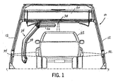
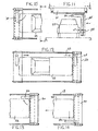
- the vehicle wash system 10 includes four spaced uprights 12 that are connected by a pair of top, side supports 14 that define the longitudinal length of the wash system 10.
- the side supports 14 are each joined by an end rail 16 to define a top frame for the vehicle wash system.
- each of the uprights 12 supports a pair of spaced guide rails 18.
- the spaced guide rails 18 are used to support an overhead gantry 20.
- the overhead gantry 20 is movable longitudinally along the pair of guide rails 18 to wash the vehicle 22 contained within the open wash bay.
- the frame for the vehicle wash system 10 is self-supporting and can be positioned within an open wash bay to wash the vehicle 22.
- the overhead gantry 20 includes a spray arch 24 that includes a series of spray nozzles used to wash the vehicle 22.
- the spray arch 24 is rotatable about a central axis and is movable along the length of the gantry 20. Thus, the spray arch 24 is movable across the width of the wash bay.
- the spray arch 24 includes a top arm 26 and a side arm 28 that each include a series of nozzles used to apply both water and soap to the vehicle 22 during the wash process.
- the side arm 28 is angled to generally correspond to the side profile of a vehicle.
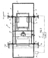
- the vehicle wash system 10 includes an instruction sign 30 that includes operational instructions for the driver of the vehicle 22 as the vehicle is positioned within the wash bay of the vehicle wash system.
- the instruction sign 30 includes various individual areas that can be lit to provide the vehicle driver the proper instructions, such as to drive forward, drive back, and stop, as well as an indication of when the wash process has been completed.
- the vehicle loading system 10 of the present invention includes a right vehicle position sensor 32 and a left vehicle position sensor 34 that are used to detect the vehicle as it enters into the open wash bay between the rear pair of uprights 12.
- the right and left vehicle position sensors 32 and 34 are each mounted to one of the rear uprights 12 and are positioned above the floor at a height to detect the side of a vehicle 22 being driven into the open wash bay.
- the right and left sensors 32 and 34 are positioned near the entry to the wash system such that they detect the entire length of the vehicle, as will be described below.
- Both the right sensor 32 and the left sensor 34 are coupled to a control unit 35 that controls the operation of the wash system.
- the right vehicle position sensor 32 and the left vehicle position sensor 34 are each an ultrasonic proximity sensor that can determine the distance between the individual sensor and the side of the vehicle.
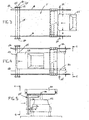
- the right vehicle position sensor 32 determines the distance between the sensor 32 and the side of the vehicle, as indicated by Y.
- the left vehicle position sensor 34 determines the distance between the sensor 34 and the left side of the vehicle, as indicated by X.
- each of the sensors 32 and 34 are connected to the control unit 35 for the vehicle wash system 10.
- Each of the sensors 32 and 34 determines the distance between itself and either the right or left side of the vehicle at numerous discrete time periods as the vehicle 22 enters into the wash bay.
- the vehicle loading system of the present invention measures and records the full side profiles of the vehicle as the vehicle enters into the wash system.
- the vehicle loading system of the present invention allows the control unit 35 of the vehicle wash system to generate a side profile for the vehicle and detect protrusions or contours in the vehicle and adjust the wash operations accordingly.
- the best example of this type of side sensing is evident in Fig. 4, in which the vehicle 22 includes rear fenders 36 that extend from the otherwise constant side profile of the vehicle. As indicated in Fig. 4, each of the rear bumpers 36 generate a measurement Y' and X' that is different from the initial front measurements X and Y made in Fig. 3.
- the control unit used to operate the vehicle wash can control the operation of the spray arch 24 and the overhead gantry based on the position of the vehicle and the side profile.
- the overhead gantry 20 includes an overhead sensor 38 that detects the height of the vehicle as the vehicle enters into the wash bay.
- the overhead sensor 38 is an ultrasonic proximity sensor that is connected to the control unit for the vehicle wash system such that the overhead sensor 38 senses the distance between the sensor 38 and the top of the vehicle at discrete time periods as the vehicle enters into the wash bay. Again, the control unit can then determine the top profile of the vehicle prior to initializing the wash process.
- the control unit 35 can control the operation of the soap and water supplied to both the top arm 26 and the side arm 28 of the spray arch 24 depending upon the top profile sensed by the overhead sensor 38. For example, if the control unit determines from the overhead sensor 38 that the vehicle being washed is a small, compact car, the control unit can turn off operation of the top arm 26 and only emit soap and water from the side arm 28, since the side arm 28 is high enough to adequately cover the entire compact car. Conversely, if the overhead sensor 38 determines that the vehicle is a large truck or sport utility vehicle, the control unit can turn on the soap and water conduits for the top arm 26 to make sure that the roof and hood of the vehicle are adequately covered. In this manner, the vehicle wash system can more efficiently distribute soap and water on vehicles based upon sensing the type of vehicle being washed.
- the overhead sensor 38 is able to positively determine the position of the back bumper of the vehicle as the overhead gantry 20 initially moves over the vehicle.
- the control unit 35 can accurately determine the position of the back of the vehicle, as well as the position of each side prior to beginning the wash process.
- the vehicle wash system 10 includes a front sensor array 40 mounted to each of the front uprights 12.
- the front sensor array 40 includes three individual through-beam sensors that each generate a through beam transmitted across the width of the vehicle wash bay.
- the front sensor array 40 includes a first front sensor 42, a second front sensor 44 and a third front sensor 46 that are spaced from each other along a mounting block 48.
- the first, second and third front sensors 42-46 include an emitter contained on the left mounting block 48 and a corresponding receiver contained on the right mounting block 50.
- each of the sensors 42-46 generates a through-beam across the width of the vehicle wash bay.
- the front bumper 52 breaks a first through-beam 54 generated by the first front sensor 42.
- the control unit for the vehicle wash system operates the sign 30 (Fig. 2) to instruct the customer to slow down.
- the front bumper 52 will break a second beam 56 generated by the second front sensor 44.
- the control unit operates the sign 30 to instruct the customer to stop. If the customer stops the vehicle before breaking the third beam 58, the sign will indicate to the customer that the vehicle is correctly positioned within the vehicle wash bay.
- the front bumper 52 will break the third beam 58 generated by the third front sensor 46. If the third beam 58 is broken, the control unit will indicate to the consumer that the vehicle has travelled too far within the wash bay and request that the vehicle be backed up until only the first and second beams 54 and 56 are broken. Once the vehicle is correctly positioned, the sign 30 indicates that the vehicle should be placed in park and the wash process will begin.
- the elimination of the "target" device on the floor of the wash bay allows the consumer to easily back up in the wash bay to correctly position the vehicle.
- the prior art system which utilized a ramp to position the front end of the vehicle, the reversal of the vehicle direction created problems in the wash process.
- the vehicle loading system of the present invention allows the control unit for the vehicle wash system to accurately locate the front bumper, rear bumper, make a side profile determination for the vehicle, and a top profile determination for the vehicle before the wash process begins. Based on the readings from the individual sensors, the control unit for the vehicle wash system can adjust the operation of the overhead gantry and the spray arch such that the spray arch is correctly positioned relative to the vehicle during the wash operation.
- An additional advantage of the present system is that the vehicle is positioned within the wash bay based on the front bumper of the vehicle. By knowing the accurate position of the front bumper, the vehicle wash system can more accurately locate the front of the car to improve cleaning. Current systems that locate the front tire positions have problems associated with the different vehicle dimensions between the front bumper and the front tire.
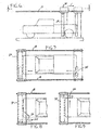
- the control unit is able to make a complete and accurate profile of the position of the vehicle as well as a determination of the distance of the vehicle between the right vehicle position sensor 32 and the left vehicle position sensor 34. Based on this determination, the control unit moves the spray arch 24 until the side arm 28 is the desired distance X" from the outermost side portion of the vehicle 22. In the embodiment of the invention illustrated in Fig. 5, the outermost portion is the extended rear bumper 36.
- the overhead gantry 20 is moved in the direction illustrated by arrow 60 of Fig. 6 to a home position, as illustrated in phantom.
- the overhead sensor 38 can locate the back bumper of the vehicle. From the home position, the gantry 20 moves along the guide rails 18 such that the spray arch 24 washes the side of the vehicle 22.
- the spray arch 24 is rotated 90° and the spray arch is moved laterally across the front of the vehicle, as illustrated in Figs. 8 and 9.
- the spray arch again rotates 90° into the position shown in Fig. 10.
- the control unit moves the spray arch 24 until the side arm 28 is the required distance Y" from the outermost side portion of the vehicle 22.
- the gantry 20 moves in the direction illustrated by arrow 62 to its rear position, as illustrated in Fig. 12. During this movement, the spray arch 24 washes the right side of the vehicle.
- the spray arch is rotated 90° to the position illustrated in Fig. 13. Once in position, the spray arch is moved laterally across the rear of the vehicle, as illustrated in Fig. 14. In this manner, the spray arch and gantry 20 are able to wash the entire vehicle while it is positioned within the wash bay.
- the vehicle loading system of the present invention is able to accurately position the vehicle within an open wash bay without the use of a "target device", such as a ramp that receives the front tire of a vehicle.
- the vehicle loading system of the present invention is thus able to more quickly load a vehicle within the open wash bay. This is due to the customer being allowed much more freedom to position themselves within the wash bay, since the system of the present invention can detect the position of the vehicle and adjust the operation of the gantry accordingly.
- the vehicle positioning system of the present invention has over thirty-two times the parking tolerance of current floor-mounted system, which allows the customer to proceed into the wash bay faster and improves the customer's wash experience.
- An additional advantage of the present invention is that the elimination of the floor-mounted "target" alignment system eliminates the large amount of maintenance and installation costs for the vehicle wash machine. Additionally, the elimination of the target system reduces any limitations to the physical size, width, or tire size of the vehicle being washed within the system.
Landscapes
- Engineering & Computer Science (AREA)
- Mechanical Engineering (AREA)
- Vehicle Cleaning, Maintenance, Repair, Refitting, And Outriggers (AREA)
Claims (23)
- Système de lavage d'un véhicule (10) pour laver un véhicule positionné dans une baie de lavage, le système comprenant:un portique mobile surplombant (20) englobant un arceau de pulvérisation (24) pour laver un véhicule (22) dans la baie de lavage;une unité de commande (35) destinée à contrôler le déplacement du portique surplombant (20) et de l'arceau de pulvérisation (24) dans la baie de lavage au cours du lavage du véhicule (22);un premier capteur de la position du véhicule (32) destiné à déterminer la distance entre le premier capteur de la position du véhicule (32) et un premier côté du véhicule (22), le premier capteur de la position du véhicule (32) étant connecté à l'unité de commande (35);un deuxième capteur de la position du véhicule (34) destiné à déterminer la distance entre le deuxième capteur de la position du véhicule (34) et un deuxième côté du véhicule (22), le deuxième capteur de la position du véhicule (34) étant connecté à l'unité de commande (35); etun ensemble de capteurs frontaux (40) positionné de sorte à détecter l'avant du véhicule (22) lors de l'entrée du véhicule (22) dans la baie de lavage, l'ensemble de capteurs frontaux étant accouplé à l'unité de commande (35);l'unité de commande (35) contrôlant le fonctionnement du portique surplombant (20) et de l'arceau de pulvérisation (24) sur la base des distances détectées entre le véhicule (22) et le premier capteur de la position du véhicule (32) et le deuxième capteur de la position du véhicule (34), l'unité de commande (35) transmettant un signal pour arrêter le déplacement du véhicule (22) lors de la détection de l'extrémité avant du véhicule (22) par l'ensemble de capteurs.
- Système selon la revendication 1, dans lequel le premier capteur de la position du véhicule (32) et le deuxième capteur de la position du véhicule (34) sont chacun constitués par des capteurs de proximité à ultrasons.
- Système selon la revendication 2, dans lequel le premier capteur de la position du véhicule (32) et le deuxième capteur de la position du véhicule (34) déterminent la distance entre le capteur respectif et le véhicule (22) à des moments multiples, de sorte que l'unité de commande (35) reçoit de multiples mesures de la distance des premier et deuxième capteurs du véhicule (34) lors de l'entrée du véhicule (22) dans la baie de lavage.
- Système selon la revendication 1, comprenant en outre un capteur surélevé (38) monté sur le portique mobile surplombant (20), le capteur surélevé (38) étant destiné à déterminer la distance entre le capteur surélevé (38) et la partie supérieure du véhicule (22) positionné dans la baie de lavage.
- Système selon la revendication 4, dans lequel le capteur surélevé (38) est constitué par un capteur de proximité à ultrasons.
- Système selon la revendication 5, dans lequel le capteur surélevé (38) est connecté à l'unité de commande (35), de sorte que l'unité de commande (35) actionne le portique surplombant (20) et l'arceau de pulvérisation (24) sur la base de la distance entre le capteur surélevé (38) et le véhicule (22).
- Système selon la revendication 6, dans lequel le capteur surélevé (38) effectue de multiples mesures au cours du déplacement relatif entre le portique surplombant (20) et le véhicule (22), de sorte que le capteur surélevé (38) détermine le profil supérieur du véhicule (22).
- Système selon la revendication 4, dans lequel le capteur surélevé (38) est monté sur le portique surplombant (20).
- Système selon la revendication 1, dans lequel l'ensemble de capteurs avant (40) englobe un premier capteur frontal (42) et un deuxième capteur frontal (46) destinés chacun à détecter la présence du véhicule (22), l'unité de commande (35) signalant le positionnement approprié du véhicule (22) lorsque seul le premier capteur (42) détecte le véhicule (22), l'unité de commande (35) signalant le positionnement non approprié du véhicule (22) lorsque le premier capteur frontal et le deuxième capteur frontal (46) détectent la présence du véhicule (22).
- Système selon la revendication 9, dans lequel le premier capteur frontal (42) et le deuxième capteur frontal (46) sont constitués par des capteurs à faisceau traversant.
- Système selon la revendication 9, comprenant en outre un affichage électronique (30) positionné dans la baie de lavage et accouplé à l'unité de commande (35), l'unité de commande (35) actionnant l'affichage de sorte à indiquer la position appropriée et non appropriée du véhicule (22).
- Procédé de chargement d'un véhicule (22) dans une baie de lavage et de commande du fonctionnement du système de lavage du véhicule (10) selon l'une quelconque des revendications précédentes pour laver le véhicule (22) lorsque le véhicule (22) est à l'arrêt dans la baie de lavage, le procédé comprenant les étapes ci-dessous:signalisation du positionnement approprié du véhicule (22) dans la baie de lavage lorsqu'un premier capteur frontal (42) de l'ensemble des capteurs frontaux (40) détecte le véhicule (22) et signalisation de la position non appropriée du véhicule (22) lorsque le premier capteur frontal (42) et le deuxième capteur frontal (46) du groupe de capteurs frontaux (40) détectent la présence du véhicule (22);détermination de la distance entre le premier capteur de la position du véhicule (32) et un premier côté du véhicule (22);détermination de la distance entre le deuxième capteur de la position du véhicule (34) et un deuxième côté du véhicule (22);réception des distances déterminées par le premier capteur de la position du véhicule (32) et le deuxième capteur de la position du véhicule (34) dans l'unité de commande (35); etcontrôle du déplacement du portique surplombant (20) et de l'arceau de pulvérisation (24) par rapport au véhicule à l'arrêt sur la base des distances déterminées.
- Procédé selon la revendication 12, comprenant en outre les étapes ci-dessous:détection de la hauteur du véhicule (22) dans la baie de lavage; etcontrôle du fonctionnement de l'arceau de pulvérisation (24) sur la base de la hauteur du véhicule (22) dans la baie de lavage.
- Procédé selon la revendication 13, dans lequel l'étape de détermination de la hauteur du véhicule (22) dans la baie de lavage englobe les étapes ci-dessous:détermination de la distance entre un capteur surélevé (38) et la partie supérieure du véhicule (22); etréception de la distance mesurée du capteur surélevé (38) dans l'unité de commande (235), l'unité de commande (35) contrôlant le fonctionnement de l'arceau de pulvérisation (24) sur la base de la distance mesurée par le capteur surélevé (38).
- Procédé selon la revendication 14, dans lequel le capteur surélevé (38) effectue de multiples mesures de la distance par rapport à la longueur longitudinale du véhicule (22), de sorte que l'unité de commande (35) peut établir un profil supérieur basé sur les multiples mesures de la distance.
- Procédé selon la revendication 12, dans lequel l'unité de commande (35) contrôle le déplacement de l'arceau de pulvérisation (24) vers les premier et deuxième côtés du véhicule (22) et à l'écart de ceux-ci sur la base des distances mesurées par le premier capteur de la position du véhicule (32) et le deuxième capteur de la position du véhicule (34).
- Procédé selon la revendication 12, dans lequel le premier capteur de la position du véhicule (32) et le deuxième capteur de la position du véhicule (34) sont constitués par des capteurs de proximité à ultrasons stationnaires.
- Procédé selon la revendication 12, dans lequel le premier capteur de la position du véhicule (32) et le deuxième capteur de la position du véhicule (34) sont chacun actionnés à des intervalles prédéterminés, de sorte que le premier capteur de la position du véhicule (32) et le deuxième capteur de la position du véhicule (34) effectuent de multiples mesures de la distance le long des premier et deuxième côtés du véhicule (22), les multiples mesures de la distance étant enregistrées dans l'unité de commande (35).
- Procédé selon la revendication 18, dans lequel les multiples mesures de la distance sont reçues dans l'unité de commande (35) avant le déplacement du portique surplombant (20) et de l'arceau de pulvérisation (24).
- Procédé selon la revendication 18, dans lequel le profil latéral de chaque côté du véhicule (22) est établi avant le déplacement du portique surplombant (20) et de l'arceau de pulvérisation (24) par l'unité de commande (35) pour laver le véhicule (22).
- Procédé selon la revendication 12, dans lequel l'unité de commande (35) reçoit les distances mesurées par le premier capteur de la position du véhicule (32) et par le deuxième capteur de la position du véhicule (34) avant le déplacement du portique surplombant (20) et de l'arceau de pulvérisation (24).
- Procédé selon la revendication 12, comprenant en outre les étapes ci-dessous:positionnement d'un capteur surélevé (38) sur le portique surplombant (20), le capteur surélevé (38), étant destiné à détecter la position d'une extrémité arrière du véhicule (22); etaccouplement du capteur surélevé (38) à l'unité de commande (35), de sorte que l'unité de commande (35) peut déterminer la position de l'extrémité arrière du véhicule (22) dans la baie de lavage.
- Procédé selon la revendication 22, dans lequel le capteur surélevé (38) est constitué par un capteur de proximité à ultrasons.
Applications Claiming Priority (3)
| Application Number | Priority Date | Filing Date | Title |
|---|---|---|---|
| US20323200P | 2000-05-08 | 2000-05-08 | |
| US203232P | 2000-05-08 | ||
| PCT/US2001/014427 WO2001085507A1 (fr) | 2000-05-08 | 2001-05-04 | Dispositif de positionnement sans contact pour baie de lavage automatique de vehicule |
Publications (2)
| Publication Number | Publication Date |
|---|---|
| EP1280687A1 EP1280687A1 (fr) | 2003-02-05 |
| EP1280687B1 true EP1280687B1 (fr) | 2005-11-02 |
Family
ID=22753073
Family Applications (1)
| Application Number | Title | Priority Date | Filing Date |
|---|---|---|---|
| EP01931056A Expired - Lifetime EP1280687B1 (fr) | 2000-05-08 | 2001-05-04 | Dispositif de positionnement sans contact pour baie de lavage automatique de vehicule |
Country Status (8)
| Country | Link |
|---|---|
| US (5) | US6425407B2 (fr) |
| EP (1) | EP1280687B1 (fr) |
| AU (2) | AU5753101A (fr) |
| CA (1) | CA2415613C (fr) |
| DE (1) | DE60114602T2 (fr) |
| ES (1) | ES2252226T3 (fr) |
| NZ (1) | NZ522776A (fr) |
| WO (1) | WO2001085507A1 (fr) |
Families Citing this family (46)
| Publication number | Priority date | Publication date | Assignee | Title |
|---|---|---|---|---|
| EP1280687B1 (fr) * | 2000-05-08 | 2005-11-02 | Delaware Capital Formation, Inc. | Dispositif de positionnement sans contact pour baie de lavage automatique de vehicule |
| US6508260B2 (en) * | 2001-02-27 | 2003-01-21 | Hydrobotic Technologies, Inc. | Vehicle washing system |
| US7318442B2 (en) * | 2004-04-14 | 2008-01-15 | Macdowell Michael | Automatic car wash system |
| US7337791B1 (en) * | 2004-04-20 | 2008-03-04 | Belanger, Inc. | Rollover car wash for large vehicles |
| US20080190445A1 (en) * | 2004-05-24 | 2008-08-14 | R. Lewis Technologies, Inc. | Method and Apparatus for Cleaning Vehicles |
| US20050279385A1 (en) * | 2004-06-16 | 2005-12-22 | Ryko Manufacturing Company | Apparatus and method for positioning a vehicle in the wash area of a vehicle wash system |
| US20060065292A1 (en) * | 2004-09-30 | 2006-03-30 | Moore Kenneth S | Automatic car wash with high pressure wand |
| US7438075B1 (en) | 2004-12-30 | 2008-10-21 | Washworld, Inc. | Spray arch controller for a carwash |
| HK1074346A2 (en) * | 2005-01-13 | 2005-11-04 | Hutchison International Ports Enterprises Limited | Parking aid apparatus |
| USD532525S1 (en) * | 2005-05-31 | 2006-11-21 | Caldwell Russell L | Building structure for a carwash |
| DE102005027721A1 (de) * | 2005-06-16 | 2007-01-04 | Dürr Ecoclean GmbH | Reinigungsvorrichtung und Verfahren zum Reinigen von Werkstücken |
| US7797881B2 (en) * | 2005-06-22 | 2010-09-21 | Loitherstein Joel S | Garage door control system |
| USD534659S1 (en) * | 2005-07-06 | 2007-01-02 | Caldwell Russell L | Building structure for a carwash |
| USD533671S1 (en) * | 2005-07-06 | 2006-12-12 | Caldwell Russell L | Building structure for a carwash |
| USD535756S1 (en) * | 2005-07-06 | 2007-01-23 | Caldwell Russell L | Building structure for a carwash |
| USD532526S1 (en) * | 2005-07-06 | 2006-11-21 | Caldwell Russell L | Building structure for a carwash |
| US20070034235A1 (en) * | 2005-08-12 | 2007-02-15 | Belanger, Inc. | Method and apparatus for washing cars |
| ES2283193B1 (es) * | 2005-09-22 | 2008-08-16 | Lavados Laving, S.A. | Sistema para el lavado de vehiculos. |
| EP1767418A3 (fr) * | 2005-09-22 | 2007-06-06 | Lavados Laving, S.A. | Dispositif de lavage pour véhicules automobiles |
| PL1806265T3 (pl) * | 2006-01-10 | 2009-04-30 | Financiere Clairac | Zrobotyzowany układ mycia pojazdu |
| US20080066790A1 (en) * | 2006-09-20 | 2008-03-20 | Rems Brian J | Autonomous Personal Vehicle Washing and Drying System |
| ITAN20070012U1 (it) * | 2007-05-16 | 2008-11-17 | O M G Di Geminiani Gino | Impianto per lavaggio automezzi, con rilevazione tirdimensionale della forma geometrica degli stessi, con ugelli orientabili automaticamente in funzione delle superfici rilevate |
| ITMI20071038A1 (it) * | 2007-05-23 | 2008-11-24 | Ceccato & Co | Impianto del tipo senza spazzole e procedimento di lavaggio automatico di veicoli |
| US7784475B2 (en) * | 2008-02-19 | 2010-08-31 | Motor City Wash Works, Inc. | High pressure arch for a vehicle wash system |
| US7770588B2 (en) * | 2008-02-29 | 2010-08-10 | Harrell's Equipment & Supply Co., Inc. | Automated motorcycle wash |
| US8813765B2 (en) * | 2008-05-01 | 2014-08-26 | Petit Auto Wash, Inc. | Vehicle wash systems and methods |
| DE102008034571A1 (de) * | 2008-07-24 | 2010-02-04 | Wash Tec Holding Gmbh | Radleitschiene, Fahrzeugwaschanlage und Verfahren zum mittigen Positionieren eines Fahrzeugs |
| ES2322930B1 (es) * | 2009-03-30 | 2010-05-25 | Barin, S.A. | Sistema de lavado de vehiculos sin contacto. |
| US8383207B2 (en) * | 2009-04-28 | 2013-02-26 | Zep Ip Holding Llc | Configurable application of a tire dressing |
| US8379925B2 (en) * | 2009-04-28 | 2013-02-19 | Zep Ip Holding Llc | Determination of tire parameters for configurable application of a tire dressing |
| CN102385434B (zh) * | 2010-08-31 | 2015-11-25 | 富泰华工业(深圳)有限公司 | 电子装置及电子装置关机方法 |
| US9634977B2 (en) | 2012-10-01 | 2017-04-25 | Salesforce.Com, Inc. | Systems and methods of redactive messaging |
| ES2398275B1 (es) * | 2012-10-18 | 2013-10-11 | Guzmán DE L'HOTELLERIE DE FALLOIS ALBALAT | Equipo limpiador autónomo |
| US9802579B2 (en) | 2013-02-14 | 2017-10-31 | Peter J. Anderson | Vehicle wash system |
| CA2886427C (fr) | 2014-03-28 | 2022-10-18 | Ryan D. Oliver | Lave-auto sans contact equipe d'un systeme de convoyeur |
| DE102015212316A1 (de) * | 2015-07-01 | 2017-01-05 | Robert Bosch Gmbh | Sensorgerät für einen Parkplatz |
| US20170100499A1 (en) * | 2015-10-07 | 2017-04-13 | Integrated Solutions for Systems, Inc. | Decontamination Systems and Methods |
| WO2018097759A1 (fr) * | 2016-11-28 | 2018-05-31 | Андрей Васильевич ЧЕРЕДНИЧЕНКО | Dispositif de lavage de voitures |
| CN107363011B (zh) * | 2017-08-28 | 2023-09-05 | 中信戴卡股份有限公司 | 一种智能轮毂清洗装置 |
| DE102018108343A1 (de) * | 2018-04-09 | 2019-10-10 | Washtec Holding Gmbh | Verfahren zum automatischen Erkennen einer Ladefläche |
| US11540443B2 (en) | 2019-01-31 | 2023-01-03 | Deere & Company | System and method for measurement of harvested material in a cleaning assembly |
| CN109668523B (zh) * | 2019-02-14 | 2022-06-03 | 宁波中令清洁技术有限公司 | 一种车辆外轮廓的检测装置 |
| KR102257065B1 (ko) * | 2020-09-18 | 2021-05-26 | 양석원 | 자동 세차장치 |
| GB2610211A (en) * | 2021-08-26 | 2023-03-01 | The Orange Train Wash Ltd | Train wash |
| US12427951B2 (en) | 2022-11-09 | 2025-09-30 | AutoMap Vehicle Wash Systems, Inc. | Vehicle wash system |
| KR102607769B1 (ko) * | 2023-07-28 | 2023-11-29 | 주식회사 디케이워시 | 회전 및 좌우 이동노즐이 적용된 세차시스템 |
Family Cites Families (59)
| Publication number | Priority date | Publication date | Assignee | Title |
|---|---|---|---|---|
| US3042303A (en) | 1959-04-24 | 1962-07-03 | Gen Railway Signal Co | Object or vehicle detection system |
| US3167797A (en) * | 1962-05-23 | 1965-02-02 | Om Edwards Co Inc | Apparatus for vehicle washing |
| US3299901A (en) * | 1965-04-07 | 1967-01-24 | Om Edwards Co Inc | Car washing apparatus |
| US3533422A (en) * | 1967-05-29 | 1970-10-13 | Washindrive Intern Corp | Automatic vehicle washing mechanism |
| US3474801A (en) * | 1967-07-28 | 1969-10-28 | Robert J Stotts | Automatic car wash |
| US3529611A (en) * | 1968-03-15 | 1970-09-22 | Delta Mfg & Eng Corp | Vehicle washing apparatus |
| US3596241A (en) * | 1969-02-04 | 1971-07-27 | Maurice Migneault | Signalling apparatus and method for car washes and the like |
| US3604434A (en) * | 1969-03-21 | 1971-09-14 | Malsbary Mfg Co | Automatic carwash apparatus |
| US3543774A (en) * | 1969-09-18 | 1970-12-01 | Homestead Ind Inc | Vehicle washing apparatus |
| US3736948A (en) * | 1971-07-28 | 1973-06-05 | B Crosswhite | Washing and sanitizing apparatus for carts such as hospital carts |
| GB1443146A (en) * | 1972-09-07 | 1976-07-21 | Ultrasonic Machines Ltd | Vehicle washing machines |
| US4674069A (en) | 1982-12-16 | 1987-06-16 | Omron Tateisi Electronics Co. | System for collecting and processing data relating to moving bodies |
| JPS6015156A (ja) * | 1983-07-08 | 1985-01-25 | 高島屋日発工業株式会社 | 積層内装品の端末処理方法およびこれに使用するパツド材剥離装置 |
| JPS60151156A (ja) * | 1984-01-19 | 1985-08-09 | Nippon Sharyo Senjiyouki Kk | 洗車機の噴水装置 |
| US4726388A (en) | 1984-07-13 | 1988-02-23 | Swinehart Lonn L | Automatic vehicle washing equipment |
| US4587688A (en) | 1985-03-04 | 1986-05-13 | Gougoulas Harry K | Proximity detector system for automatic car washer/dryer equipment |
| US4719932A (en) * | 1985-05-21 | 1988-01-19 | Pdq Manufacturing Inc. | Automatic vehicle washing system |
| US4852593A (en) * | 1985-06-14 | 1989-08-01 | Magic Spray Inc. | Apparatus and method for washing vehicles |
| US4718439A (en) | 1985-12-04 | 1988-01-12 | Syndet Products, Inc. | Vehicle washing system having apparatus for following a vehicle surface contour |
| US4857113A (en) * | 1985-12-23 | 1989-08-15 | Grace-Lee Products, Inc. | Vehicle cleansing method |
| US4716916A (en) * | 1985-12-23 | 1988-01-05 | Grace-Lee Products, Inc. | Vehicle cleansing |
| US4981523A (en) | 1986-05-09 | 1991-01-01 | Sherman Industries, Inc. | Vehicle cleaning system and method |
| DE3635213A1 (de) | 1986-10-16 | 1988-04-28 | Kaercher Gmbh & Co Alfred | Fahrzeugwaschanlage |
| US4856543A (en) | 1987-04-10 | 1989-08-15 | Petit Thomas J | Vehicle washing device |
| US4850379A (en) | 1987-04-10 | 1989-07-25 | Petit Thomas J | Vehicle washing device |
| US4794938A (en) | 1987-04-10 | 1989-01-03 | Petit Thomas J | Vehicle washing device |
| US4949423A (en) | 1987-06-08 | 1990-08-21 | Sherman Industries, Inc. | Dryer for automatic car wash equipment |
| US4946513A (en) | 1990-04-20 | 1990-08-07 | Sherman Industries, Inc. | Automated car wash system |
| US4988042A (en) | 1987-08-12 | 1991-01-29 | Sherman Industries, Inc. | Automated car wash system |
| US4933016A (en) * | 1989-01-18 | 1990-06-12 | Mark Carlson | Car wash |
| US5040485A (en) * | 1990-02-23 | 1991-08-20 | National Pride Co. | Automatic car wash system |
| US5033490A (en) | 1990-02-23 | 1991-07-23 | Wade Jerry D | Car wash adjustable to car size |
| US5173692A (en) | 1990-08-13 | 1992-12-22 | Ai Computer Services, Inc. | System and method of vehicle detection |
| DE4025937A1 (de) * | 1990-08-16 | 1992-02-20 | Hoechst Ag | Verfahren zur herstellung von phosphoriger saeure |
| US5161557A (en) * | 1990-11-15 | 1992-11-10 | D & S Manufacturing Co. | Brushless vehicle washing apparatus |
| US5255695A (en) * | 1991-03-01 | 1993-10-26 | Emil Downey | Vehicle washing apparatus |
| US5226436A (en) * | 1992-05-29 | 1993-07-13 | Ryko Manufacturing Co. | Wheel position sensor for car wash car sizing |
| US5291906A (en) * | 1992-12-21 | 1994-03-08 | S.N.M. Manufacturing , Inc. | Automatic vehicle cleaning system |
| JP2834385B2 (ja) | 1993-05-10 | 1998-12-09 | 株式会社 ニッポー技研 | 自動洗車方法及びその装置 |
| US5528234A (en) | 1994-02-01 | 1996-06-18 | Mani; Siva A. | Traffic monitoring system for determining vehicle dimensions, speed, and class |
| US5482212A (en) * | 1994-07-05 | 1996-01-09 | Kobryn; Scott | Vehicle washing machine |
| JP3488751B2 (ja) * | 1994-09-01 | 2004-01-19 | エムケー精工株式会社 | 洗車方法および装置 |
| FI101277B1 (fi) * | 1995-04-21 | 1998-05-29 | Tammermatic Oy | Ajoneuvonpesulaite |
| JPH0924802A (ja) * | 1995-07-10 | 1997-01-28 | Mk Seiko Co Ltd | 超音波洗浄ノズルを備えた洗車機 |
| JP3269961B2 (ja) * | 1996-02-06 | 2002-04-02 | 三菱電機株式会社 | マルチビーム衛星通信システムにおけるビーム自動選択切替方法および装置 |
| JP3785249B2 (ja) * | 1997-06-26 | 2006-06-14 | アベテック株式会社 | 自動洗車機 |
| DE29723828U1 (de) | 1997-10-17 | 1999-03-25 | California Kleindienst Holding GmbH, 86153 Augsburg | Fahrzeugbehandlungsanlage mit Meßeinrichtungen |
| US6134735A (en) | 1998-11-02 | 2000-10-24 | Miracle Industries, Inc. | Vehicle washing apparatus |
| US5886648A (en) | 1998-02-02 | 1999-03-23 | Proto-Vest, Inc. | Automated vehicle wash system with vehicle type recognition |
| FI111450B (fi) * | 1998-02-05 | 2003-07-31 | Tammermatic Oy | Menetelmä ajoneuvojen pesemiseksi |
| WO1999061295A1 (fr) * | 1998-05-26 | 1999-12-02 | California Kleindienst Holding Gmbh | Installation de traitement de vehicule et son procede de fonctionnement |
| DE29809426U1 (de) | 1998-05-26 | 1999-10-07 | California Kleindienst Holding GmbH, 86153 Augsburg | Einfahrhilfe |
| DE29903300U1 (de) | 1998-11-05 | 2000-03-23 | California Kleindienst Holding GmbH, 86153 Augsburg | Einfahrhilfe für Fahrzeugbehandlungsanlagen |
| DE29821066U1 (de) * | 1998-11-25 | 2000-03-30 | Wesumat Fahrzeugwaschanlagen GmbH, 86156 Augsburg | Vorrichtung zur Positionierung von Kraftfahrzeugen vor Fahrzeugwaschanlagen, insbesondere Portalwaschanlagen |
| JP4341864B2 (ja) * | 1999-07-26 | 2009-10-14 | 澁谷工業株式会社 | 気液混合流の噴射装置 |
| US6277207B1 (en) * | 1999-08-02 | 2001-08-21 | Mark Vii Equipment, Inc. | Control system for vehicle washing system |
| US6372053B1 (en) | 1999-10-01 | 2002-04-16 | Michael J. Belanger | Rollover pressure car wash apparatus and methods of operating same |
| EP1280687B1 (fr) * | 2000-05-08 | 2005-11-02 | Delaware Capital Formation, Inc. | Dispositif de positionnement sans contact pour baie de lavage automatique de vehicule |
| US6508260B2 (en) * | 2001-02-27 | 2003-01-21 | Hydrobotic Technologies, Inc. | Vehicle washing system |
-
2001
- 2001-05-04 EP EP01931056A patent/EP1280687B1/fr not_active Expired - Lifetime
- 2001-05-04 DE DE60114602T patent/DE60114602T2/de not_active Expired - Fee Related
- 2001-05-04 WO PCT/US2001/014427 patent/WO2001085507A1/fr not_active Ceased
- 2001-05-04 AU AU5753101A patent/AU5753101A/xx active Pending
- 2001-05-04 ES ES01931056T patent/ES2252226T3/es not_active Expired - Lifetime
- 2001-05-04 US US09/848,918 patent/US6425407B2/en not_active Expired - Fee Related
- 2001-05-04 CA CA002415613A patent/CA2415613C/fr not_active Expired - Fee Related
- 2001-05-04 AU AU2001257531A patent/AU2001257531B2/en not_active Ceased
- 2001-05-04 NZ NZ522776A patent/NZ522776A/en unknown
-
2002
- 2002-05-03 US US10/137,883 patent/US20020124870A1/en not_active Abandoned
- 2002-09-13 US US10/242,971 patent/US6551415B2/en not_active Expired - Fee Related
-
2003
- 2003-02-25 US US10/374,841 patent/US6769440B2/en not_active Expired - Fee Related
-
2004
- 2004-07-02 US US10/884,518 patent/US20050000552A1/en not_active Abandoned
Also Published As
| Publication number | Publication date |
|---|---|
| CA2415613C (fr) | 2006-11-28 |
| WO2001085507A1 (fr) | 2001-11-15 |
| CA2415613A1 (fr) | 2001-11-15 |
| AU2001257531B2 (en) | 2004-08-19 |
| DE60114602T2 (de) | 2006-08-03 |
| US20030015222A1 (en) | 2003-01-23 |
| AU5753101A (en) | 2001-11-20 |
| US6551415B2 (en) | 2003-04-22 |
| US20020124870A1 (en) | 2002-09-12 |
| DE60114602D1 (de) | 2005-12-08 |
| EP1280687A1 (fr) | 2003-02-05 |
| ES2252226T3 (es) | 2006-05-16 |
| US6769440B2 (en) | 2004-08-03 |
| US20050000552A1 (en) | 2005-01-06 |
| US20020002986A1 (en) | 2002-01-10 |
| NZ522776A (en) | 2003-10-31 |
| US20030145877A1 (en) | 2003-08-07 |
| US6425407B2 (en) | 2002-07-30 |
Similar Documents
| Publication | Publication Date | Title |
|---|---|---|
| AU2001257531B2 (en) | Touch free loading system for an automatic in-bay vehicle wash system | |
| AU2001257531A2 (en) | Touch free loading system for an automatic in-bay vehicle wash system | |
| AU2001257531A1 (en) | Touch free loading system for an automatic in-bay vehicle wash system | |
| US7100621B2 (en) | Sidetrack vehicle washer with rotating spray arm | |
| US7438075B1 (en) | Spray arch controller for a carwash | |
| CN101980904B (zh) | 轮引导轨道、车辆清洗设备和用于居中定位车辆的方法 | |
| US20050279385A1 (en) | Apparatus and method for positioning a vehicle in the wash area of a vehicle wash system | |
| US20070034235A1 (en) | Method and apparatus for washing cars | |
| JP6742762B2 (ja) | 停車補助装置及びそれを備えた洗車装置 | |
| US11173880B2 (en) | Method for operating a vehicle washing system, and vehicle washing system | |
| CN210402733U (zh) | 一种洗车机停车引导系统 | |
| JP2017210007A (ja) | 洗車装置 | |
| CN112033322B (zh) | 一种自动停车系统及其底盘高度检测装置 | |
| JP4621387B2 (ja) | 洗車装置 | |
| JP3152817B2 (ja) | 門型洗車機 | |
| US6992595B2 (en) | Device for detecting the position of a vehicle for a vehicle treatment facility | |
| JPH10287213A (ja) | 洗車装置 | |
| JP2023029018A (ja) | 洗車機 | |
| CN113859182A (zh) | 停车定位系统、停车定位方法及洗车方法 | |
| JP6961357B2 (ja) | 洗車装置およびタイヤ検出装置 | |
| KR101824591B1 (ko) | 차량용 휠 세척 방법 | |
| JPH06278577A (ja) | 洗車装置 | |
| CN2893818Y (zh) | 泊车辅助装置 | |
| JPH06321068A (ja) | 洗車装置 | |
| JP2001042938A (ja) | 移動車運行制御システムと移動車と移動車運行方法 |
Legal Events
| Date | Code | Title | Description |
|---|---|---|---|
| PUAI | Public reference made under article 153(3) epc to a published international application that has entered the european phase |
Free format text: ORIGINAL CODE: 0009012 |
|
| 17P | Request for examination filed |
Effective date: 20021202 |
|
| AK | Designated contracting states |
Designated state(s): AT BE CH CY DE DK ES FI FR GB GR IE IT LI LU MC NL PT SE TR |
|
| AX | Request for extension of the european patent |
Extension state: AL LT LV MK RO SI |
|
| RBV | Designated contracting states (corrected) |
Designated state(s): DE ES FI FR GB IT |
|
| 17Q | First examination report despatched |
Effective date: 20040929 |
|
| GRAP | Despatch of communication of intention to grant a patent |
Free format text: ORIGINAL CODE: EPIDOSNIGR1 |
|
| RAP1 | Party data changed (applicant data changed or rights of an application transferred) |
Owner name: DELAWARE CAPITAL FORMATION, INC. |
|
| GRAS | Grant fee paid |
Free format text: ORIGINAL CODE: EPIDOSNIGR3 |
|
| GRAA | (expected) grant |
Free format text: ORIGINAL CODE: 0009210 |
|
| AK | Designated contracting states |
Kind code of ref document: B1 Designated state(s): DE ES FI FR GB IT |
|
| PG25 | Lapsed in a contracting state [announced via postgrant information from national office to epo] |
Ref country code: FI Free format text: LAPSE BECAUSE OF FAILURE TO SUBMIT A TRANSLATION OF THE DESCRIPTION OR TO PAY THE FEE WITHIN THE PRESCRIBED TIME-LIMIT Effective date: 20051102 |
|
| REG | Reference to a national code |
Ref country code: GB Ref legal event code: FG4D |
|
| REF | Corresponds to: |
Ref document number: 60114602 Country of ref document: DE Date of ref document: 20051208 Kind code of ref document: P |
|
| REG | Reference to a national code |
Ref country code: ES Ref legal event code: FG2A Ref document number: 2252226 Country of ref document: ES Kind code of ref document: T3 |
|
| PLBE | No opposition filed within time limit |
Free format text: ORIGINAL CODE: 0009261 |
|
| STAA | Information on the status of an ep patent application or granted ep patent |
Free format text: STATUS: NO OPPOSITION FILED WITHIN TIME LIMIT |
|
| 26N | No opposition filed |
Effective date: 20060803 |
|
| EN | Fr: translation not filed | ||
| PG25 | Lapsed in a contracting state [announced via postgrant information from national office to epo] |
Ref country code: FR Free format text: LAPSE BECAUSE OF FAILURE TO SUBMIT A TRANSLATION OF THE DESCRIPTION OR TO PAY THE FEE WITHIN THE PRESCRIBED TIME-LIMIT Effective date: 20061222 |
|
| PGFP | Annual fee paid to national office [announced via postgrant information from national office to epo] |
Ref country code: DE Payment date: 20080530 Year of fee payment: 8 Ref country code: ES Payment date: 20080528 Year of fee payment: 8 |
|
| PG25 | Lapsed in a contracting state [announced via postgrant information from national office to epo] |
Ref country code: FR Free format text: LAPSE BECAUSE OF FAILURE TO SUBMIT A TRANSLATION OF THE DESCRIPTION OR TO PAY THE FEE WITHIN THE PRESCRIBED TIME-LIMIT Effective date: 20051102 |
|
| PGFP | Annual fee paid to national office [announced via postgrant information from national office to epo] |
Ref country code: IT Payment date: 20080531 Year of fee payment: 8 |
|
| PGFP | Annual fee paid to national office [announced via postgrant information from national office to epo] |
Ref country code: GB Payment date: 20080521 Year of fee payment: 8 |
|
| GBPC | Gb: european patent ceased through non-payment of renewal fee |
Effective date: 20090504 |
|
| PG25 | Lapsed in a contracting state [announced via postgrant information from national office to epo] |
Ref country code: GB Free format text: LAPSE BECAUSE OF NON-PAYMENT OF DUE FEES Effective date: 20090504 |
|
| PG25 | Lapsed in a contracting state [announced via postgrant information from national office to epo] |
Ref country code: DE Free format text: LAPSE BECAUSE OF NON-PAYMENT OF DUE FEES Effective date: 20091201 |
|
| REG | Reference to a national code |
Ref country code: ES Ref legal event code: FD2A Effective date: 20090505 |
|
| PG25 | Lapsed in a contracting state [announced via postgrant information from national office to epo] |
Ref country code: ES Free format text: LAPSE BECAUSE OF NON-PAYMENT OF DUE FEES Effective date: 20090505 |
|
| PG25 | Lapsed in a contracting state [announced via postgrant information from national office to epo] |
Ref country code: IT Free format text: LAPSE BECAUSE OF NON-PAYMENT OF DUE FEES Effective date: 20090504 |