EP1280720B1 - Förderer mit zuführungssystem - Google Patents
Förderer mit zuführungssystem Download PDFInfo
- Publication number
- EP1280720B1 EP1280720B1 EP01940467A EP01940467A EP1280720B1 EP 1280720 B1 EP1280720 B1 EP 1280720B1 EP 01940467 A EP01940467 A EP 01940467A EP 01940467 A EP01940467 A EP 01940467A EP 1280720 B1 EP1280720 B1 EP 1280720B1
- Authority
- EP
- European Patent Office
- Prior art keywords
- article
- conveyor
- speed
- gap
- photo
- Prior art date
- Legal status (The legal status is an assumption and is not a legal conclusion. Google has not performed a legal analysis and makes no representation as to the accuracy of the status listed.)
- Expired - Lifetime
Links
- 238000000034 method Methods 0.000 claims description 45
- 238000011144 upstream manufacturing Methods 0.000 claims description 26
- 230000008859 change Effects 0.000 claims description 23
- 230000001133 acceleration Effects 0.000 claims description 9
- 230000007704 transition Effects 0.000 claims description 8
- 108091008695 photoreceptors Proteins 0.000 claims description 4
- 238000005259 measurement Methods 0.000 claims description 3
- 238000012544 monitoring process Methods 0.000 claims description 3
- 238000009825 accumulation Methods 0.000 description 10
- 230000006698 induction Effects 0.000 description 6
- 238000001514 detection method Methods 0.000 description 5
- 108020003175 receptors Proteins 0.000 description 5
- 230000001419 dependent effect Effects 0.000 description 4
- 230000006870 function Effects 0.000 description 4
- 230000008569 process Effects 0.000 description 4
- 238000004364 calculation method Methods 0.000 description 3
- 230000009467 reduction Effects 0.000 description 3
- 238000003491 array Methods 0.000 description 2
- 238000010586 diagram Methods 0.000 description 2
- 230000005484 gravity Effects 0.000 description 2
- 230000032258 transport Effects 0.000 description 2
- 230000008901 benefit Effects 0.000 description 1
- 230000006872 improvement Effects 0.000 description 1
- 230000004048 modification Effects 0.000 description 1
- 238000012986 modification Methods 0.000 description 1
- 230000003252 repetitive effect Effects 0.000 description 1
- 230000004044 response Effects 0.000 description 1
- 230000004043 responsiveness Effects 0.000 description 1
Images


Classifications
-
- B—PERFORMING OPERATIONS; TRANSPORTING
- B65—CONVEYING; PACKING; STORING; HANDLING THIN OR FILAMENTARY MATERIAL
- B65G—TRANSPORT OR STORAGE DEVICES, e.g. CONVEYORS FOR LOADING OR TIPPING, SHOP CONVEYOR SYSTEMS OR PNEUMATIC TUBE CONVEYORS
- B65G43/00—Control devices, e.g. for safety, warning or fault-correcting
- B65G43/08—Control devices operated by article or material being fed, conveyed or discharged
-
- B—PERFORMING OPERATIONS; TRANSPORTING
- B65—CONVEYING; PACKING; STORING; HANDLING THIN OR FILAMENTARY MATERIAL
- B65G—TRANSPORT OR STORAGE DEVICES, e.g. CONVEYORS FOR LOADING OR TIPPING, SHOP CONVEYOR SYSTEMS OR PNEUMATIC TUBE CONVEYORS
- B65G43/00—Control devices, e.g. for safety, warning or fault-correcting
- B65G43/10—Sequence control of conveyors operating in combination
-
- B—PERFORMING OPERATIONS; TRANSPORTING
- B65—CONVEYING; PACKING; STORING; HANDLING THIN OR FILAMENTARY MATERIAL
- B65G—TRANSPORT OR STORAGE DEVICES, e.g. CONVEYORS FOR LOADING OR TIPPING, SHOP CONVEYOR SYSTEMS OR PNEUMATIC TUBE CONVEYORS
- B65G47/00—Article or material-handling devices associated with conveyors; Methods employing such devices
- B65G47/22—Devices influencing the relative position or the attitude of articles during transit by conveyors
- B65G47/26—Devices influencing the relative position or the attitude of articles during transit by conveyors arranging the articles, e.g. varying spacing between individual articles
- B65G47/30—Devices influencing the relative position or the attitude of articles during transit by conveyors arranging the articles, e.g. varying spacing between individual articles during transit by a series of conveyors
- B65G47/31—Devices influencing the relative position or the attitude of articles during transit by conveyors arranging the articles, e.g. varying spacing between individual articles during transit by a series of conveyors by varying the relative speeds of the conveyors forming the series
Definitions
- the induction section of a conveyor system generally refers to the portion of the conveying system in which articles are inducted, or initiated, into the conveying sortation system.
- the induction section typically performs the function of providing the proper gaps between packages, or other articles traveling on the conveying system, so that the packages can be sorted for proper distribution.
- the proper gapping between articles on the conveying system is important for a variety of reasons. First, the gapping of the articles affects the throughput of the conveying system, which is often a factor of high commercial significance. By reducing the gaps between articles on the conveying system, the number of articles that can be placed on the conveying system at a given time is increased. By being able to place more articles on the conveying system at a given time, more articles are moved over a given time period, thus increasing the throughput of the conveying system.
- the gapping of the articles is highly important because the gapping affects the sortation functions of the conveying system.
- the conveying system functions to sort the articles being conveyed
- prior art conveying systems have often used pusher shoes or other diverting means to push the articles off of a main conveyor onto one or more branch conveyors.
- pusher shoes on some sorters tend to rotate the article, at least partially, when they are in the process of diverting the article onto a branch conveyor. This rotation ensures that the articles are properly aligned with the branch conveyor when they are diverted.
- the article In order for the article to be rotated, however, it is necessary for there to be a space behind the article in order to provide room for the rotation of the article. If insufficient space is allotted, the article may contact another article while being rotated, thus causing it to enter the branch conveyor misaligned, or to not be diverted at all.
- the sortation functions of the conveying system therefore weigh in favor of providing a certain amount of gapping between articles while the throughput considerations weigh in favor of reducing this gapping to as small a space as possible.
- the induct portion of the conveying system would ideally be able to consistently and accurately produce gaps that were just large enough to accommodate the gapping requirements of the sortation section of the conveying system while rarely, if ever, exceeding these minimum gapping requirements.
- Prior art induct systems have left room for improvement as to the consistency, accuracy, and speed at which at which gapping of the articles can be performed. Particularly as increases in throughput have been based on increasing conveyor speed while reducing gapping, the necessity for precise gapping in conveyor systems has increased.
- the present invention provides an improved method and apparatus for inducting articles into a conveying system.
- the method and apparatus allow the position of articles travelling on individual conveyors to be more accurately determined, thus aiding the accuracy and precision of the gapping process.
- the method and apparatus of the present invention also allow an accurate determination, rather than an assumption, to be made as to the point at which an article moving from one conveyor to another changes from having its speed controlled by the upstream conveyor to that of the downstream conveyor.
- an apparatus for measuring of the gap between articles travelling on a conveyor system.
- the apparatus comprises the features of claim 1; advantageous embodiments of the invention are featured in dependent claims 2 - 17.
- a method for controlling a gap between a first and a second article on a conveyor comprises the features of independent claim 18; advantageous embodiments of the method are featured in dependent claims 19 - 51.
- the method and the apparatus of the present invention provide an improved induction system that allows gaps to be created between packages that are more accurate and consistent, as well as allowing the induction system to operate at higher speeds while maintaining this improved accuracy and consistency.
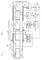
- a conveyor induct system 20 is generally depicted in plan and block diagram form in FIG. 1.
- Conveyor induct system 20 comprises two subsystems which can be utilized independently from each other or in combination with each other.
- One such subsystem is a control point determination module 38 which serves to accurately determine the location of the control points an individual articles, as will be explained in more detail below.
- the other subsystem of conveyor induct system 20 is a gap control system 40 which controls the speed of one or more of the conveyors in order to create a desired gap between articles as they exit onto a take-away conveyor 32.
- a gap control system 40 which controls the speed of one or more of the conveyors in order to create a desired gap between articles as they exit onto a take-away conveyor 32.
- Conveyor induct system 20 includes a first conveyor 22 and a second conveyor 24, both of which carry packages or other articles on their conveying surfaces 26 in the direction indicated by arrow 28.
- the particular type of conveying surface 26 is not limited within the scope of the present invention, but can include belts, rollers, slats, and any other type of conveying structure capable of transporting goods.
- a feed conveyor which may include an accumulation conveyor 30, feeds packages to induct system 20.
- a take-away conveyor 32 carries packages that have been properly gapped to a sortation system (not shown) or other downstream junction. Conveyors 30 and 32 are only partially illustrated in FIG. 1. Take away conveyor 32 is located downstream of, and aligned with, second conveyor 24 and transports articles that are transferred onto it from second conveyor 24.
- conveyors 22, 24, 30, and 32 are not necessarily drawn according to scale, and that the lengths and widths of these conveyors can vary as would be understood by one skilled in the art.
- a series of articles 34a-h ride on the conveying surfaces 26 of the various conveyors and move in the direction of arrow 28.
- Articles 34, which are not part of the invention, are depicted in various sizes and are again not necessarily drawn to scale but are depicted for purposes of description herein.
- the articles 34 that enter into conveyor induct system 20 from accumulation conveyor 30 may be generally closely packed together such that no gaps exist between these articles. While it is not necessary within the scope of the invention that such lack of gaps exists, it is desirable that excessive gaps be removed or minimized prior to the articles reaching first conveyor 22. Because articles are often manually loaded onto the conveyor system by workers unloading trucks, or other vehicles, there is often a significant amount of spacing that initially exists between articles as they are first unloaded. This spacing may be on the order of several feet and is desirably eliminated or reduced before the articles reach first conveyor 22. To that end, it may be desirable to merge several incoming conveyors into a single conveyor line so that gaps can be reduced or eliminated.
- An accumulation conveyor helps remove these gaps, provided articles are being fed into the conveyor system at a fast enough rate. It will be understood, however, that an accumulation conveyor is not a necessary component of the present invention. If an accumulation conveyor is used, it can be any of a variety of types of conventional accumulation conveyors, or other types of accumulation conveyors, as would be known by one skilled in the art.
- First conveyor 22 preferably, although not necessarily, operates at a speed that is no greater than the highest speed of the immediately upstream conveyor, which, as illustrated in FIG. 1, is accumulation conveyor 30.
- First conveyor 22 has a speed which is generally less than that of second conveyor 24 so that any gaps between articles will be enlarged as they pass from first conveyor 22 to second conveyor 24.
- first conveyor 22 may have its speed set at a fixed ratio to that of second conveyor 24 so that changes in the speed of second conveyor 24 will cause proportionate changes in the speed of first conveyor 22.
- An example of a gap created by the passage of articles from first conveyor 22 to second conveyor 24 can be seen between articles 34e and 34d. This gap will continue to increase until article 34d has passed sufficiently onto second conveyor 24 such that article 34d is carried at the same speed as second conveyor 24. After article 34d has transitioned onto second conveyor 24, the created gap between article 34d and e may or may not be equal to the desired gap.
- the creation of the desired gap is accomplished during the transition of articles from second conveyor 24 to take-away conveyor 34.
- An example of a desired gap is illustrated in FIG. 1 between the trailing edge of article 34h and the leading edge of article 34g.
- control point determination module 38 in order to find the location of the control point of each article.
- the control point of an article is the point on the article which, when it is aligned with a specified reference point on the conveyor, will designate the moment in time that the article's speed switches from being controlled by one belt to another belt. It is important to know the control point of an article during the gapping phase of the articles because adjustments in the speed of a conveyor during gapping will be ineffective in changing the speed of the article unless the article is still being controlled by the particular conveyor whose speed is being adjusted.
- Control point determination module 38 includes a horizontal array of photo-detectors 42 which comprise a first array of photo-emitters 44 and a second set of photo-receptors 46.
- the emitters 44 are positioned on an opposite side of first conveyor 22 across from, and aligned with, receptors 46.
- Photo-detector array 42 emits electromagnetic signals, such as light, infrared, or other signals, from emitters 44 across first conveyor 22 to receptors 46, which detect the emitted signal provided there is no article on first conveyor 22 that obstructs the line of sight between an emitter 44 and a receptor 46.
- Photo-detector array 42 is thus able to determine where gaps between articles are located by determining which particular photo-detectors are not obstructed at a given moment.
- Horizontal array of photo-detectors 42 which is often referred to as a light curtain, can be any type of conventional array of photo-detectors, such as those that are commercially available from Kore Computing of Comstock Park, Michigan, or SICK, Inc. of Bloomington, MN. Other types of photo-detectors can also be used.
- Photo-detector array 42 should include photo-detectors that are spaced relatively closely together so that accurate information can be gathered about the location of gaps and the position of articles traveling on first conveyor 22.
- a photo-detector positioned every five millimeters along the length of horizontal array 42 is contemplated. More compactly spaced photo-detectors would, of course, give more precise information about the location of articles and gaps, if all other factors remain equal.
- Photo-detector array 42 should give updated information about the entire array of photo-detectors multiple times a second, such as once every two milliseconds, although this update rate can vary widely within the scope of the present invention, particularly with respect to faster update rates.
- the height at which photo-detector array 42 is positioned above conveying surface 26 should be very slight so that photo-detector array 42 does not overlook articles traveling on the conveyor that are of very low height. The precise height of array 42 can therefore be varied depending upon the types of articles being sorted. In general, a height above conveying surface 26 of a few millimeters should be appropriate for most situations.
- photo-detectors 42 may also be desirable to include multiple arrays of photo-detectors 42 which are vertically stacked upon each other to give height information about articles, as well as information about article shape.
- the length of photo-detector array 42 is preferably, although not necessarily, at least half as long as the greatest expected article length. Where first conveyor 22 is expected to be used in an application that transports articles of considerable length, the length of array 42 should therefore be correspondingly increased. Photo-detector array lengths that are less than half of the greatest expected article length still fall within the scope of the invention, but do increase the probability of not being able to accurately determine an article's control point, as the following discussion will illustrate.
- Control point determination module 38 determines the location of control points on individual articles with respect to a particular reference point.
- a one dimensional frame of reference 48 is illustrated and oriented parallel to first and second conveyors 22 and 24.
- a reference point 50 is designated on frame of reference 48.
- Reference point 50 is located halfway between the downstream end of first conveyor 22 and the upstream end of second conveyor 24.
- a control point 52 is depicted on article 34d.
- control point 52 reaches reference point 50, i.e. it becomes aligned with reference point 50, the control of article 34d will switch from first conveyor 22 to second conveyor 24.
- article 34d in the position illustrated in FIG. 2, is being controlled by first conveyor 22 despite the fact that a portion of article 34d is located on second conveyor 24.
- control point determination module 38 actually measures the location of the control point.
- Control point determination module 38 measures the location of an article's control point by monitoring the gap, if there is one, between the trailing edge of article 34d and the leading edge of article 34c. As long as article 34d is still being controlled by first conveyor 22, this gap will not change. However, as soon as article 34d transitions to being controlled by second conveyor 24, which is traveling at a higher speed than first conveyor 22, article 34d will begin to advance forwardly from article 34c, thus either creating a gap between articles 34c and d, or enlarging whatever gap may have already pre-existed.
- FIG. 3 depicts the moment when the control point 52 of article 34d has reached reference point 50. At this moment, article 34d begins to separate from article 34c, thus creating a gap between articles 34c and d.
- This gap is illustrated in FIG. 3 and detected by an unobstructed beam of electromagnetic energy 54 from photo-detector array 42.
- the control point of article 34d can be determined by a calculator 56. Because the distance that each individual photo-detector is positioned away from reference point 50 is known, calculator 56 can simply calculate the control point 52 as being this same distance. This calculation of the location of control point 52, however, is based upon the longitudinal distance of control point 52 from the trailing edge of article 34d. Typically, it will be desirable to know the location of control point 52 with respect to a different landmark such as, for example, the leading edge of article 34d. Calculator 56 can easily compute this location of control point 52 by subtracting the longitudinal distance of control point 52 to the trailing edge of article 34d from the overall length of article 34d. Alternative calculation methods are, of course, also possible.
- the length of article 34d can be determined in a variety of different manners.
- One way is to have photo-detector array 42 monitor the leading edge of article 34d while it is within the detection zone of array 42. Once out of this detection zone, the speed of first conveyor 22 is recorded until the change in the gap between articles 34d and 34c occurs. At the moment at which this change in gap occurs, the recorded speed of conveyor 22 can be used to determine the distance article 34d has traveled between the time its leading edge left the photo-detector detection zone and the speed change occurred. This distance will be equal to the distance of control point 52 from the leading edge of article 34d.
- control point 52 The determination of the location of control point 52 is dependent upon what reference point is used to define control point 52. As discussed above, reference point 50 was used to define the location of control point 52. Other reference points could be used. For example, reference point 58 could alternatively be used to define control point 52. Reference point 58 is located at the very edge of the downstream end of first conveyor 22. If reference point 58 is used as the reference point, the control point 52 will be the location on article 34 that is aligned with reference point 58 at the moment the control of article 34 transitions from that of first conveyor 22 to that of second conveyor 24. This control point will correspond to a different physical location on article 34 due to the different locations of reference points 50 and 58.
- Reference point 60 which is located at the very edge of the upstream end of conveyor 24, could also be used as a reference point. And, as noted, any other reference point can be used in defining the control point so long as the particular reference point is known and used consistently throughout the rest of the conveyor system.
- control point 52 involves, in one embodiment, the creation or enlargement of gaps between articles as they transition from conveyor 22 to conveyor 24, and the creation or enlargement of these gaps may be desirably controlled. These gaps are created or enlarged as a result of the higher speed of second conveyor 24 with respect to first conveyor 22. If conveyor 22 is set to run at a fixed fraction of the speed of conveyor 24, then the gaps that are created between articles transitioning from conveyor 22 to conveyor 24 will vary as the length of the articles vary. For example, if only long articles are moved over conveyor 22, they will tend to have relatively large gaps. If only small articles are moved, they will tend to have relatively smaller gaps. If both small and large articles are conveyed by conveyors 22 and 24, they will tend to have gaps of varying length. The varying lengths are due to the different amounts of time long and short articles spend moving at the speed of first conveyor 22 while the immediately downstream article is moving at the higher speed of second conveyor 24. This disparity in gap lengths is often desirably reduced or eliminated.
- any downstream gap controlling system such as gap control system 40
- gap control system 40 may not operate as effectively when articles are being input into the system with widely varying gaps. This may be become more of a problem as conveyor speeds increase.
- a controller could be added that controls the speed of first conveyor 22 such that, as soon as control point 52 is measured, the speed of first conveyor 22 is immediately brought up to that of second conveyor 24. This will substantially prevent the gaps from getting any larger after the control point is determined, and will tend to reduce the disparity in gaps that would otherwise result for large and small articles if the conveyor speeds remained at a fixed ratio.
- the controller would maintain conveyor 22 at the same speed as conveyor 24 up until the moment the control point reached the reference point. At that moment, the controller would decrease the speed of conveyor 22 with respect to conveyor 24 down to an acceptably lower speed such that the control point of the next article could be measured. After this was measured , the speed of conveyor 22 would then be increased to that of conveyor 24 again, and so on.
- this controller it would be possible to implement this controller by having it make adjustments to the speed of second conveyor 24, rather than first conveyor 22.
- this information can be fed to whatever other systems, modules, or structures that can make use of this information.
- this information is fed to gap control system 40 where it is used to more accurately control the gapping of articles exiting on take-away conveyor.
- this information could be used in an induct process such as that described in commonly assigned, U.S. patent application serial no. 09/699,170, filed September 25, 2000, and entitled High Rate Induction System, the disclosure of which is hereby incorporated herein by reference.
- Gap control system 40 includes a horizontal array of photo-detectors 62 which may be of the same type of photo-detectors as array 42.
- Array 62 is located alongside a portion of conveyor 24, a portion of conveyor 32, and the gap between conveyor 24 and conveyor 32.
- Array 62 preferably, although not necessarily, extends for a distance equal to the maximum expected length of articles that will be conveyed.
- a gap detector 64 receives the output from array 62 and uses it to determine the gap or gaps between articles that are traveling within the zone of detection of array 62. As illustrated in FIG. 1, gap detector 64 would detect both the gap between articles 34e and f and the gap between articles 34f and g.
- Gap detector 64 detects these gaps by determining which individual photo-detectors are obstructed by articles, and which are not. Based either upon the number of photo-detectors that are not obstructed between articles, or the distance between the most widely separated, non-obstructed set of continuous photo-detectors, the length of a gap can be determined. Also, by determining which individual photo-detectors are not obstructed, the location of the gap with respect to conveyor 24 can be determined based upon the known position of each of the photo-detectors.
- gap detector 64 After gap detector 64 detects the one or more gaps which are within the detection zone of array 62, it passes this information to a gap selector 66. Gap selector 66 chooses which of the gaps detected by detector 64, if there are more than one, to use in the feedback control loop that controls the speed of conveyor 24. The decision of which gap to use is based upon the location of the control point 52. In the position illustrated in FIG. 1, the control point 52 of article 34f has not yet reached the center of the space between conveyors 24 and 32. The speed of article 34f is therefore still being controlled by conveyor 24. By adjusting the speed of conveyor 24, it is therefore still possible to adjust the gap between article 34f and article 34g.
- Gap selector 66 would therefore choose this gap (between articles 34f and g) as the gap to be used within the feedback control loop. The dimensions of this gap would then be fed into a comparator which also receives an input from a desired gap 70.
- the desired gap 70 can be chosen according to the needs of the rest of the conveying system, or can be chosen in any other manner. As illustrated in FIG. 1, the gap between articles 34g and 34h should correspond to the desired gap.
- Comparator 68 compares the measured gap from gap selector 66 to the desired gap 70 and outputs the difference between these gaps to a feedback controller 72. Feedback controller 72 outputs a command to a variable speed motor controller 74 that causes controller 74 to change the speed of conveyor 24 as commanded.
- Variable speed motor controller 74 outputs a signal to a motor 76 that powers conveyor 24.
- the particular type of motor 76 is not limited by the present invention and the location of motor 76 with respect to conveyor 24 can vary from that depicted in FIG. 1.
- Feedback controller 72 may be any type of feedback controller, such as a proportional-integral-derivative (PID) controller, or any other type of feedback controller.
- PID proportional-integral-derivative
- the particular form of the feedback equation or equations used by feedback controller 72, along with the particular constants or gains used in the equation(s), will vary depending upon the type of controller used, the responsiveness of the controlled motor or motors, the feedback rate, and other factors, as would be understood by one skilled in the art. While other command rates can be used, having feedback controller 72 update and issue commands approximately twenty times per second should generally be sufficient.
- the commands issued from feedback controller 72 may be either digital or analog. If digital, the operating range of the motor is preferably digitized such that it can be commanded to operate at over one hundred different speeds. Less digitization, however, can also be used within the scope of the invention.
- the repetitive measuring of the article gaps by array 62 may take place at the same rate as the commands are issued from controller 72, or a different rate.
- feedback controller 72 will repeatedly issue commands to motor 76 to adjust its speed in order to create the desired gap between articles 34f and 34g.
- Feedback controller 72 will continue to output commands to adjust the gap between article 34f and article 34g until control point 52 reaches the midpoint between conveyors 24 and 32 (assuming the control point to be based on a reference point midway between conveyors).
- control point 52 has reached this midpoint, article 34f is no longer being controlled by conveyor 24, despite the portion of article 34f that is still physically located on conveyor 24. Adjustments to motor 76 in order to change the gap between articles 34f and 34g are therefore ineffective.
- gap selector 66 chooses the gap between articles 34e and f as the gap whose dimensions are being input into comparator 68. Thereafter, any adjustments in the speed of motor 76 will affect the gap between articles 34e and f, rather than articles 34f and g. Any necessary adjustments to the gap between articles 34e and f will continue to be implemented by gap control system 40 until the control point of article 34e reaches the midpoint between conveyors 24 and 32. At that point, the gapping control will switch to the next downstream gap, and so on.
- control point information allows the gap control system 40 to continue to make any necessary changes in the gap of interest right up until such control is no longer possible.
- control point information also helps ensure that the changes being made to the speed of conveyor 76 will affect only the intended gap and not others.
- control point information may come from control point determination module 38, or it may come from other sources as well.
- gap control system 40 in a manner in which the conveyor whose speed was modified to control the gaps was the downstream conveyor, rather than the upstream conveyor. It would also be possible to implement multiple gap control systems 40 sequentially. Such a sequential array of gap control systems might further increase the accuracy of the final gap, particularly where the desired gap differs substantially from the gaps that pre-exist between the articles being fed into gap control system 40.
- gap control system 40 could be modified to include one or more additional conveyors upstream of conveyor 24 that used an open loop type of control in order to make refinements to the article gaps such that gapping control system 40 only had to make minor adjustments, if any, to create the desired gaps.
- the horizontal photo-detector arrays could be replaced by other sensors that provided repeated updates about the status of gaps and the position of articles.
- One such sensor could be a camera or cameras appropriately mounted to visually record the movement of articles. Such video images could be processed by the appropriate software in order to measure the gaps and article lengths in order to provide input into the feedback loop.
- An acoustic sensor could also be used as an alternative to the photo-detector array, as well as still further types of sensors.
Landscapes
- Engineering & Computer Science (AREA)
- Mechanical Engineering (AREA)
- Attitude Control For Articles On Conveyors (AREA)
- Control Of Conveyors (AREA)
Claims (51)
- Förderzuführungssystem, das folgendes umfaßt:gekennzeichnet durch:einen ersten Förderer (24), wobei der erste Förderer ein Förderer mit justierbarer Geschwindigkeit ist;einen zweiten Förderer (32), der auf den ersten Förderer (24) mit justierbarer Geschwindigkeit ausgerichtet ist, wobei der zweite Förderer (32) mit einer anderen Geschwindigkeit als der erste Förderer (24) betrieben werden kann;einen Controller, der einen Befehl zum Justieren der Geschwindigkeit des ersten Förderers (24) mit justierbarer Geschwindigkeit ausgibt, um eine gewünschte Lücke zwischen einem ersten Artikel (34f) und einem zweiten Artikel (34g) zu justieren, während sie sich auf dem ersten Förderer (24) und dem zweiten Förderer (32) bewegen;wobei der Controller (72) ein Rückkopplungscontroller ist, der Informationen von dem Sensor (62) empfängt, wobei der Rückkopplungscontroller (72) eine etwaige Differenz zwischen der gemessenen Lücke (64) und einer gewünschten Lücke (70) berechnet, wobei der Rückkopplungscontroller (72) einen Befehl zum Justieren der Geschwindigkeit des Förderers (24) mit justierbarer Geschwindigkeit auf der Basis einer etwaigen Differenz zwischen der gemessenen Lücke und der gewünschten Lücke ausgibt.einen Sensor (62), der eine etwaige Lücke zwischen einem ersten Artikel (34f) und einem zweiten Artikel (34g) wiederholt mißt, während der erste Artikel (34f) zumindest teilweise auf dem ersten Förderer (24) mit justierbarer Geschwindigkeit undder zweite Artikel (34g) auf dem zweiten Förderer (32) positioniert ist;
- System nach Anspruch 1, wobei der Sensor (62) eine etwaige Lücke zwischen dem ersten (34f) und dem zweiten Artikel (34g) mindestens zehnmal pro Sekunde mißt.
- Förderzuführungssystem nach Anspruch 1, gekennzeichnet durch
einen dritten Förderer (22), der vor dem ersten Förderer (24) angeordnet ist und
auf den ersten Förderer (24) ausgerichtet ist,
wobei der dritte Förderer (22) mit einer anderen Geschwindigkeit als der erste Förderer (24) arbeitet; und
einen anderen Sensor (42), der einen Steuerpunkt (52) eines Artikels (34d) ausmißt, während der Artikel (34d) von dem dritten Förderer (22) zu dem ersten Förderer (24) läuft. - System nach Anspruch 3, wobei der andere Sensor (42) ein horizontales Array von Photodetektoren umfaßt.
- System nach Anspruch 1, wobei der Sensor (62) die Stelle einer Vorderkante des ersten Artikels (34f) und eine Hinterkante des zweiten Artikels (34g) im wesentlichen zur gleichen Zeit mißt.
- System nach Anspruch 3, gekennzeichnet dadurch, daß
der andere Sensor (42) dafür ausgelegt ist zu detektieren, wann in dem Artikel (34d), aufgrund dessen eine Geschwindigkeitsänderung auftritt, daß sich der Artikel ausreichend auf den ersten Förderer (24) derart bewegt hat, daß der erste Förderer (24) die Geschwindigkeit des Artikels (34d) steuert. - System nach Anspruch 1, wobei der Sensor (62) ein horizontales Array von Photodetektoren umfaßt.
- System nach Anspruch 7, wobei das horizontale Array von Photodetektoren sich von dem ersten (24) zum zweiten Förderer (32) derart erstreckt, daß ein Teil des horizontalen Arrays entlang des ersten Förderers (24) und ein Teil des horizontalen Arrays entlang des zweiten Förderers (32) positioniert ist.
- System nach Anspruch 1, wobei der erste Förderer (24) vor dem zweiten Förderer (32) positioniert ist.
- System nach Anspruch 9, wobei der erste Artikel (34f) vor dem zweiten Artikel (34g) positioniert ist.
- System nach Anspruch 6, das weiterhin einen Controller (56) enthält, der den Steuerpunkt (52) des Artikels (34d) als ein Punkt auf dem Artikel (34d) berechnet, der auf einen festgelegten Referenzpunkt (50) ausgerichtet ist, wenn die Geschwindigkeitsänderung auftritt.
- System nach Anspruch 11, wobei der Referenzpunkt (50) etwa in der Mitte zwischen dem dritten (22) und dem ersten Förderer (24) liegt.
- System nach Anspruch 6, wobei der andere Sensor (42) ein horizontales Array von Photodetektoren umfaßt, die entlang des dritten Förderers (22) positioniert sind.
- System nach Anspruch 13, wobei das horizontale Array von Photodetektoren sich über eine horizontale Entfernung erstreckt, die mindestens gleich der Entfernung der größten erwarteten Länge des Artikels (34) ist.
- System nach Anspruch 14, wobei das horizontale Array von Photodetektoren ein oberes Ende und ein unteres Ende aufweist, wobei das untere Ende in der Mitte zwischen dem ersten und dem dritten Förderer (22, 24) plaziert ist und das obere Ende vor dem unteren Ende plaziert ist.
- System nach Anspruch 1, wobei der Rückkopplungscontroller (72) ein Proportional-Integral-Differential-Regler ist.
- System nach Anspruch 1, wobei der Rückkopplungscontroller (72) mehrere Befehle pro Sekunde ausgibt, um die Geschwindigkeit des Förderers (24) mit justierbarer Geschwindigkeit zu justieren.
- Verfahren zum Steuern einer Lücke zwischen einem ersten Artikel (34f) und einem zweiten Artikel (34g), die sich auf einem Fördersystem bewegen, umfassen:gekennzeichnet durch:Bereitstellen eines ersten Förderers (24), wobei der erste Förderer (24) ein Förderer mit justierbarer Geschwindigkeit ist;Bereitstellen eines zweiten Förderers (32), der auf den ersten Förderer (24) ausgerichtet ist;Messen einer etwaigen Lücke zwischen dem ersten Artikel (34f) und dem zweiten Artikel (34g) in einem ersten Augenblick, wenn der erste Artikel (34f) zumindest teilweise auf dem ersten Förderer (24) positioniert ist;Berechnen einer etwaigen Differenz zwischen einer gewünschten Lücke und der im ersten Augenblick gemessenen Lücke;Erzeugen eines ersten Befehls zum Justieren der Geschwindigkeit des ersten Förderers (24), um eine etwaige Differenz zwischen der gewünschten Lücke und der im ersten Augenblick gemessenen Lücke zu reduzieren, wobei der Befehl auf der Differenz zwischen der gewünschten Lücke und der im ersten Augenblick gemessenen Lücke basiert;Messen einer etwaigen Lücke zwischen dem ersten Artikel (34f) und dem zweiten Artikel (34g) in einem zweiten Augenblick, wenn der erste Artikel (34f) zumindest teilweise auf dem ersten Förderer (24) und der zweite Artikel (34g) auf dem zweiten Förderer (32) positioniert ist;Berechnen einer etwaigen Differenz zwischen der gewünschten Lücke und der im zweiten Augenblick gemessenen Lücke undErzeugen eines zweiten Befehls zum Justieren der Geschwindigkeit des ersten Förderers (24), um eine etwaige Differenz zwischen der gewünschten Lücke und der im zweiten Augenblick gemessenen Lücke zu reduzieren, wobei der Befehl auf der Differenz zwischen der gewünschten Lücke und der im zweiten Augenblick gemessenen Lücke basiert.
- Verfahren nach Anspruch 18, wobei das Messen einer etwaigen Lücke entweder im ersten oder zweiten Augenblick folgendes umfaßt:Messen der Stelle einer Vorderkante des ersten Artikels (34f) zu einem bestimmten Zeitpunkt;Messen der Stelle einer Hinterkante des zweiten Artikels (34g) im wesentlichen zum gleichen Zeitpunkt, als wenn die Vorderkante des ersten Artikels gemessen wird; undBestimmen der Entfernung zwischen der Vorderkante des ersten Artikels (34f) und der Hinterkante des zweiten Artikels (34g).
- Verfahren nach Anspruch 18, wobei der erste Förderer (24) vor dem zweiten Förderer (32) positioniert ist.
- Verfahren nach Anspruch 20, wobei der erste Artikel (34f) vor dem zweiten Artikel (34g) positioniert ist.
- Verfahren nach Anspruch 18, wobei der erste Befehl proportional zu der Differenz zwischen der gewünschten Lücke und der im ersten Augenblick gemessenen Lücke ist.
- Verfahren nach Anspruch 18, wobei der erste und zweite Befehl innerhalb einer Sekunde oder weniger voneinander erzeugt werden.
- Verfahren nach Anspruch 22, wobei das Messen der Lücken im ersten und zweiten Augenblick in einem Abstand von weniger als einer Sekunde stattfindet.
- Verfahren nach Anspruch 18, wobei das Messen einer etwaigen Lücke im ersten Augenblick weiterhin das Bereitstellen eines horizontalen Arrays von Photodetektoren (62) umfaßt, die zumindest teilweise entlang des ersten Förderers (24) mit justierbarer Geschwindigkeit positioniert sind.
- Verfahren nach Anspruch 18, wobei der erste Befehl mindestens einhundert verschiedene Geschwindigkeiten für den ersten Förderer (24) mit justierbarer Geschwindigkeit spezifizieren kann.
- Verfahren nach Anspruch 18, das weiterhin das Messen eines Steuerpunkts (52) eines Artikels (34d) beinhaltet, während der Artikel (34d) über einen Übergangspunkt zwischen zwei Förderern (22, 24) läuft.
- Verfahren nach Anspruch 27, wobei die beiden Förderer (22, 24) den ersten Förderer (24) mit justierbarer Geschwindigkeit und einen vor dem ersten Förderer (24) mit justierbarer Geschwindigkeit liegenden dritten Förderer (22) umfassen.
- Verfahren nach Anspruch 27, wobei das Messen des Steuerpunkts folgendes umfaßt:Detektieren, wann eine Änderung bei der Geschwindigkeit des Artikels (34d) auftritt, während der Artikel den Übergangspunkt überquert; undBestimmen des Steuerpunkts (52) des Artikels (34d) als der Punkt auf dem Artikel (34d), der auf einen festen Referenzpunkt (50) ausgerichtet ist, wenn die Geschwindigkeitsänderung auftritt.
- Verfahren nach Anspruch 18, wobei der erste Artikel (34f) vor dem zweiten Artikel (34g) positioniert ist.
- Verfahren nach Anspruch 18, wobei das Messen einer etwaigen Lücke zwischen dem ersten Artikel (34f) und dem zweiten Artikel (34g) weiterhin das Bereitstellen eines horizontalen Arrays von Photodetektoren (62) umfaßt, die zumindest teilweise entlang des Förderers (24) mit justierbarer Geschwindigkeit positioniert sind.
- Verfahren nach Anspruch 31, wobei das Array von Photodetektoren (62) ein Array von Photoemittern enthält, die entlang einer ersten Seite des Förderers (24) mit justierbarer Geschwindigkeit positioniert sind, und ein Array von Photorezeptoren, die entlang einer zweiten Seite des Förderers (24) mit justierbarer Geschwindigkeit positioniert sind, wobei das Array von Photoemittern periodisch elektromagnetische Signale emittiert, die von dem Array von Photorezeptoren detektiert werden, es sei denn, daß ein oder mehrere Artikel (34a-h) auf dem Förderer (24) mit justierbarer Geschwindigkeit zwischen dem Array von Photoemittern und dem Array von Photorezeptoren positioniert sind.
- Verfahren nach Anspruch 18, weiterhin mit dem Messen der Länge des ersten Artikels (34f).
- Verfahren nach Anspruch 18, gekennzeichnet durch:Bereitstellen eines dritten Förderers (22) mit einem unteren Ende, wobei der dritte Förderer (22) eine erste artikelbefördernde Oberfläche (26) aufweist;Bereitstellen eines weiteren Förderers (erster Förderer 24) mit einem oberen Ende, das auf das untere Ende des dritten Förderers (22) ausgerichtet ist, wobei der weitere Förderer eine zweite artikelbefördernde Oberfläche (26) aufweist, die zumindest gelegentlich mit einer anderen Geschwindigkeit als die erste artikelbefördernde Oberfläche (26) arbeitet; undBestimmen eines Steuerpunkts (52), bei dem ein Artikel (34d) sich von einem Förderer (22) zu einem anderen (24) bewegt, einschließlich des Detektierens, wann eine Geschwindigkeitsänderung des Artikels (34d) auftritt, so daß sich der Artikel (34d) ausreichend von der zweiten fördernden Oberfläche (26) zu der ersten fördernden Oberfläche (26) derart bewegt hat, daß die Geschwindigkeit des Artikels (34d) von der zweiten fördernden Oberfläche (26) anstatt von der ersten fördernden Oberfläche (26) gesteuert wird.
- Verfahren nach Anspruch 34, wobei der Steuerpunkt (52) so eingestellt ist, daß er der Punkt auf dem Artikel (34d) ist, der auf einen festen Referenzpunkt (50) ausgerichtet ist, wenn die Geschwindigkeitsänderung auftritt.
- Verfahren nach Anspruch 34, wobei das Detektieren der Geschwindigkeitsänderung des Artikels (34d) das Detektieren einer Änderung beim Abstand zwischen dem Artikel (34d) und einem vorgeschalteten Artikel (34c) neben dem Artikel (34d) umfaßt.
- Verfahren nach Anspruch 35, wobei der feste Referenzpunkt (50) in der Mitte zwischen dem dritten (22) und den weiteren Förderern (erster Förderer 24) liegt.
- Verfahren nach Anspruch 34, das weiterhin folgendes umfaßt:Bereitstellen eines horizontalen Arrays von Photodetektoren (42), die entlang des dritten Förderers (22) positioniert sind; undÜberwachen der Photodetektoren (42), um zu bestimmen, wann die Geschwindigkeitsänderung des Artikels (34d) auftritt.
- Verfahren nach Anspruch 34, weiterhin mit dem Begrenzen der Beschleunigung des Förderers (24) mit justierbarer Geschwindigkeit.
- Verfahren nach Anspruch 38, weiterhin mit dem Detektieren einer Änderung beim Abstand zwischen dem Artikel (34d) und einem vorgeschalteten Artikel (34c) neben dem Artikel (34d).
- Verfahren nach Anspruch 34, weiterhin mit dem Justieren der relativen Geschwindigkeit der ersten fördernden Oberfläche (26) bezüglich der zweiten fördernden Oberfläche (26), nachdem der Steuerpunkt (52) bestimmt worden ist.
- Verfahren nach Anspruch 41, wobei das Justieren der relativen Geschwindigkeit der ersten fördernden Oberfläche (26) bezüglich der zweiten fördernden Oberfläche (26) das Einstellen der Geschwindigkeiten der ersten und zweiten fördernden Oberflächen (26) beinhaltet, daß sie einander gleich sind.
- Verfahren nach Anspruch 34, weiterhin mit dem Detektieren einer Vorderkante des Artikels (34d), Bestimmen der Position der Vorderkante des Artikels (34d) auf der zweiten fördernden Oberfläche (26), wenn die Geschwindigkeitsänderung auftritt, und Berechnen der Entfernung der Vorderkante von dem Steuerpunkt (52) des Artikels (34d).
- Verfahren nach Anspruch 39, weiterhin mit dem Ändern der Grenze der Beschleunigung des Förderers (24) mit justierbarer Geschwindigkeit zumindest teilweise auf der Basis der Messung des Steuerpunkts (52) des ersten Artikels (34f).
- Verfahren nach Anspruch 29, wobei das Detektieren der Geschwindigkeitsänderung des ersten Artikels (34f) das Detektieren einer Änderung beim Abstand zwischen dem ersten Artikel (34f) und einem dritten Artikel (34e) neben und vor dem ersten Artikel (34f) umfaßt.
- Verfahren nach Anspruch 27, weiterhin mit dem Begrenzen der Beschleunigung des ersten Förderers (24) mit justierbarer Geschwindigkeit zumindest teilweise auf der Basis der Messung des Steuerpunkts (52).
- Verfahren nach Anspruch 18, wobei das Messen der Lücke folgendes umfaßt:Messen der Stelle einer Vorderkante des ersten Artikels (34f) zu einem bestimmten Zeitpunkt;Messen der Stelle einer Hinterkante des zweiten Artikels (34g) im wesentlichen zum gleichen Zeitpunkt, wie die Vorderkante des ersten Artikels (34f) gemessen wird; undBestimmen der Entfernung zwischen der Vorderkante des ersten Artikels (34f) und der Hinterkante des zweiten Artikels (34g).
- Verfahren nach Anspruch 47, das weiterhin folgendes umfaßt:erneutes Messen der Lücke zwischen dem ersten Artikel (34f) und dem zweiten Artikel (34g), während sich der erste Artikel (34f) zumindest teilweise noch auf dem Förderer (24) mit justierbarer Geschwindigkeit befindet; undNeujustieren der Geschwindigkeit des Förderers (24) mit justierbarer Geschwindigkeit auf der Basis einer etwaigen Differenz zwischen der wiedergemessenen Lücke und der gewünschten Lücke.
- Verfahren nach Anspruch 48, wobei das Wiedermessen der Lücke und das Neujustieren der Geschwindigkeit mehrmals pro Sekunde wiederholt werden.
- Verfahren nach Anspruch 34, wobei das Messen des Steuerpunkts (52) eines Artikels (34a-h), wenn der Artikel von dem dritten Förderer (22) zum ersten Förderer (24) läuft, folgendes umfaßt:Bestimmen des Steuerpunkts (52) des Artikels (34a-h) als der Punkt auf dem Artikel, der auf einen festen Referenzpunkt (50) ausgerichtet ist, wenn die Geschwindigkeitsänderung auftritt.
- Verfahren nach Anspruch 50, wobei das Detektieren der Geschwindigkeitsänderung des Artikels (34d) das Detektieren einer Änderung beim Abstand zwischen dem Artikel (34d) und einem anderen Artikel (34c) neben und vor dem Artikel (34d) umfaßt.
Applications Claiming Priority (3)
| Application Number | Priority Date | Filing Date | Title |
|---|---|---|---|
| US20330100P | 2000-05-11 | 2000-05-11 | |
| US203301P | 2000-05-11 | ||
| PCT/EP2001/005445 WO2001085582A1 (en) | 2000-05-11 | 2001-05-11 | Conveyor induct system |
Publications (2)
| Publication Number | Publication Date |
|---|---|
| EP1280720A1 EP1280720A1 (de) | 2003-02-05 |
| EP1280720B1 true EP1280720B1 (de) | 2005-03-23 |
Family
ID=22753377
Family Applications (1)
| Application Number | Title | Priority Date | Filing Date |
|---|---|---|---|
| EP01940467A Expired - Lifetime EP1280720B1 (de) | 2000-05-11 | 2001-05-11 | Förderer mit zuführungssystem |
Country Status (10)
| Country | Link |
|---|---|
| US (2) | US6629593B2 (de) |
| EP (1) | EP1280720B1 (de) |
| JP (1) | JP2003532601A (de) |
| AU (2) | AU7403201A (de) |
| BR (1) | BR0110938B1 (de) |
| CA (1) | CA2408673C (de) |
| DE (1) | DE60109595T2 (de) |
| ES (1) | ES2238448T3 (de) |
| MX (1) | MXPA02011074A (de) |
| WO (1) | WO2001085582A1 (de) |
Cited By (3)
| Publication number | Priority date | Publication date | Assignee | Title |
|---|---|---|---|---|
| DE102015206695A1 (de) | 2015-04-15 | 2016-10-20 | Krones Ag | Verfahren und Transportsystem zum Steuern eines Behälterstroms |
| IT202100002873A1 (it) | 2021-02-11 | 2021-05-11 | Mas Pack S P A | Apparato per attuare una distanza fisica tra un gruppo di pacchi contigui ed una serie di pacchi accumulati |
| EP4299484A1 (de) * | 2022-06-30 | 2024-01-03 | Siemens Aktiengesellschaft | Verfahren zur steuerung einer mit retrofitting zugefügten förderstrecke für stückgüter |
Families Citing this family (107)
| Publication number | Priority date | Publication date | Assignee | Title |
|---|---|---|---|---|
| US6513641B1 (en) * | 1999-10-12 | 2003-02-04 | Rapistan Systems Advertising Corp. | High rate induction system |
| US6629593B2 (en) * | 2000-05-11 | 2003-10-07 | Rapistan Systems Advertising Corp. | Conveyor induction system |
| US6812426B1 (en) * | 2000-07-24 | 2004-11-02 | Rapiscan Security Products | Automatic reject unit spacer and diverter |
| US6763931B1 (en) * | 2001-11-06 | 2004-07-20 | Christopher R. Brehm | Conveyor system |
| WO2003042078A1 (en) * | 2001-11-16 | 2003-05-22 | Crisplant A/S | Conveyor unit with timer controlled delay of speed change |
| US6923307B2 (en) | 2001-11-21 | 2005-08-02 | Rapistan Systems Advertising Corp. | High volume conveyor sortation system |
| EP1927938B1 (de) * | 2002-05-16 | 2014-07-16 | United Parcel Service Of America, Inc. | Verfahren zur Packetsortierung und Zustellung unter Verwendung von RFID Technologie |
| US7963695B2 (en) | 2002-07-23 | 2011-06-21 | Rapiscan Systems, Inc. | Rotatable boom cargo scanning system |
| US8275091B2 (en) | 2002-07-23 | 2012-09-25 | Rapiscan Systems, Inc. | Compact mobile cargo scanning system |
| DE10236170A1 (de) * | 2002-08-07 | 2004-03-25 | Siemens Ag | Lastabhängiger Asynchronantrieb für eine Förderstrecke |
| DE50212361D1 (de) * | 2002-09-13 | 2008-07-24 | Mueller Martini Holding Ag | Förderanordnung zur Verarbeitung von Druckprodukten |
| US7017291B2 (en) * | 2003-05-12 | 2006-03-28 | Finishtech, Ltd. | Gap reduction system and method for laundry processing |
| US6928141B2 (en) | 2003-06-20 | 2005-08-09 | Rapiscan, Inc. | Relocatable X-ray imaging system and method for inspecting commercial vehicles and cargo containers |
| US20050072655A1 (en) * | 2003-10-03 | 2005-04-07 | Glen Raque | Transport system |
| US7191895B2 (en) * | 2003-10-07 | 2007-03-20 | Dematic Corp. | Conveyor induct system with probability estimator |
| ATE399712T1 (de) * | 2004-03-11 | 2008-07-15 | Cfs Buehl Gmbh | Vorrichtung zum versiegeln von behältern durch anbringen einer deckelfolie |
| US8417374B2 (en) * | 2004-04-19 | 2013-04-09 | Curt G. Joa, Inc. | Method and apparatus for changing speed or direction of an article |
| GB2414460A (en) * | 2004-05-25 | 2005-11-30 | Syspal Ltd | Conveyor system |
| EP1758803A1 (de) * | 2004-06-21 | 2007-03-07 | Siemens Corporate Research, Inc. | Platzsparender hochleistungs-artikelvereinzeler |
| DE102004035821A1 (de) * | 2004-07-23 | 2006-02-16 | Siemens Ag | Verfahren und Vorrichtung zur dynamischen Lückenoptimierung |
| US20060032192A1 (en) * | 2004-08-13 | 2006-02-16 | Mcleod Jesse | Transporter device |
| DE102005002461B3 (de) * | 2005-01-18 | 2006-07-06 | Martin Dr. Neumann | Antrieb für ein Endoskop |
| US7471764B2 (en) | 2005-04-15 | 2008-12-30 | Rapiscan Security Products, Inc. | X-ray imaging system having improved weather resistance |
| CN101304934A (zh) * | 2005-11-09 | 2008-11-12 | 株式会社安川电机 | 排列输送器装置 |
| US7694614B2 (en) * | 2005-12-01 | 2010-04-13 | Walgreen, Co | Case cutter assembly |
| WO2007067944A2 (en) | 2005-12-07 | 2007-06-14 | Dematic Corp. | High volume conveyor sortation system |
| US7720567B2 (en) * | 2005-12-09 | 2010-05-18 | Cornerstone Automation Systems, Inc. | Automated box opening apparatus |
| DE102006030434A1 (de) * | 2006-05-03 | 2007-11-08 | CFS Bühl GmbH | Zuführvorrichtung für einen Traysealer |
| US9433538B2 (en) | 2006-05-18 | 2016-09-06 | Curt G. Joa, Inc. | Methods and apparatus for application of nested zero waste ear to traveling web and formation of articles using a dual cut slip unit |
| US10456302B2 (en) | 2006-05-18 | 2019-10-29 | Curt G. Joa, Inc. | Methods and apparatus for application of nested zero waste ear to traveling web |
| WO2008008716A2 (en) * | 2006-07-10 | 2008-01-17 | Dematic Corp. | Conveyor system with dynamic gapping and method of slug building |
| US7854314B2 (en) * | 2007-01-08 | 2010-12-21 | Dematic Corp. | Dynamic singulator |
| US9550306B2 (en) | 2007-02-21 | 2017-01-24 | Curt G. Joa, Inc. | Single transfer insert placement and apparatus with cross-direction insert placement control |
| US9944487B2 (en) | 2007-02-21 | 2018-04-17 | Curt G. Joa, Inc. | Single transfer insert placement method and apparatus |
| DE102007021146A1 (de) * | 2007-05-03 | 2008-11-06 | Focke & Co.(Gmbh & Co. Kg) | Vorrichtung und Verfahren zum Handhaben von flachen Gegenständen, insbesondere Windeln |
| DE102007024673A1 (de) * | 2007-05-25 | 2008-12-04 | Holtec Gmbh & Co. Kg Anlagenbau Zur Holzbearbeitung | Rundholzfördereinrichtung |
| FR2919598B1 (fr) * | 2007-08-02 | 2009-12-04 | Solystic | Dispositif de convoyage d'envois avec un asservissement sur le taux de rejet |
| DE102007040367B4 (de) * | 2007-08-17 | 2022-11-17 | Ssi Schäfer Automation Gmbh | Materialflusssteuerung zur Kollisionsvermeidung in einer Förderanlage |
| JP5345623B2 (ja) * | 2007-08-22 | 2013-11-20 | レイトラム リミテッド ライアビリティー カンパニー | 荷物間に間隔を設けるコンベヤと方法 |
| US20090171501A1 (en) * | 2007-12-26 | 2009-07-02 | Hills Steven L | Systems and method for maintaining a gap between successive objects |
| GB0803641D0 (en) | 2008-02-28 | 2008-04-02 | Rapiscan Security Products Inc | Scanning systems |
| GB0803644D0 (en) | 2008-02-28 | 2008-04-02 | Rapiscan Security Products Inc | Scanning systems |
| GB0809110D0 (en) | 2008-05-20 | 2008-06-25 | Rapiscan Security Products Inc | Gantry scanner systems |
| EP2135825B1 (de) * | 2008-06-17 | 2012-05-16 | Langenpac B.V. | Verfahren, Vorrichtung und System zur Ausrichtung von Papiertaschentuchpackstücken |
| US8201681B2 (en) * | 2008-07-14 | 2012-06-19 | Siemens Industry, Inc. | Method for gapping for sortation rate maximization |
| US8612050B2 (en) * | 2008-07-29 | 2013-12-17 | Palo Alto Research Center Incorporated | Intelligent product feed system and method |
| JP5222689B2 (ja) * | 2008-10-24 | 2013-06-26 | 伊東電機株式会社 | コンベア装置、並びに、コンベア制御装置 |
| US20100122892A1 (en) * | 2008-11-18 | 2010-05-20 | Illinois Tool Works Inc. | Registration method for multiwall paper and woven packages |
| WO2011025942A1 (en) * | 2009-08-28 | 2011-03-03 | Dematic Corp. | Conveyor induct |
| AT508864B1 (de) * | 2009-10-02 | 2012-04-15 | Tgw Mechanics Gmbh | Fördereinrichtung und verfahren zur überprüfung der einhaltung eines mindestabstandes zwischen zwei förderobjekten |
| US9089453B2 (en) | 2009-12-30 | 2015-07-28 | Curt G. Joa, Inc. | Method for producing absorbent article with stretch film side panel and application of intermittent discrete components of an absorbent article |
| JP5513137B2 (ja) * | 2010-01-05 | 2014-06-04 | トーヨーカネツソリューションズ株式会社 | アキュムレーションコンベヤ |
| DE102010035472A1 (de) | 2010-08-26 | 2012-03-01 | Siemens Aktiengesellschaft | Verfahren und Vorrichtung zum Transport von Gegenständen in mehreren parallelen Pufferstrecken |
| US8656817B2 (en) | 2011-03-09 | 2014-02-25 | Curt G. Joa | Multi-profile die cutting assembly |
| US9218933B2 (en) | 2011-06-09 | 2015-12-22 | Rapidscan Systems, Inc. | Low-dose radiographic imaging system |
| US8820380B2 (en) | 2011-07-21 | 2014-09-02 | Curt G. Joa, Inc. | Differential speed shafted machines and uses therefor, including discontinuous and continuous side by side bonding |
| CA2807809C (en) | 2012-02-20 | 2019-07-23 | Curt G. Joa, Inc. | Method of forming bonds between discrete components of disposable articles |
| US8714342B2 (en) * | 2012-03-30 | 2014-05-06 | First Solar, Inc. | System and method for gapping conveyed substrates |
| US9908739B2 (en) | 2012-04-24 | 2018-03-06 | Curt G. Joa, Inc. | Apparatus and method for applying parallel flared elastics to disposable products and disposable products containing parallel flared elastics |
| US9216924B2 (en) * | 2012-11-09 | 2015-12-22 | Corning Incorporated | Methods of processing a glass ribbon |
| KR102167245B1 (ko) | 2013-01-31 | 2020-10-19 | 라피스캔 시스템스, 인코포레이티드 | 이동식 보안검사시스템 |
| US9283683B2 (en) | 2013-07-24 | 2016-03-15 | Curt G. Joa, Inc. | Ventilated vacuum commutation structures |
| GB201314963D0 (en) * | 2013-08-21 | 2013-10-02 | Oakbridge Invest Ltd | Packaging method and apparatus |
| USD704237S1 (en) | 2013-08-23 | 2014-05-06 | Curt G. Joa, Inc. | Ventilated vacuum commutation structure |
| USD703247S1 (en) | 2013-08-23 | 2014-04-22 | Curt G. Joa, Inc. | Ventilated vacuum commutation structure |
| USD703711S1 (en) | 2013-08-23 | 2014-04-29 | Curt G. Joa, Inc. | Ventilated vacuum communication structure |
| USD703712S1 (en) | 2013-08-23 | 2014-04-29 | Curt G. Joa, Inc. | Ventilated vacuum commutation structure |
| USD703248S1 (en) | 2013-08-23 | 2014-04-22 | Curt G. Joa, Inc. | Ventilated vacuum commutation structure |
| ES2944915T3 (es) * | 2013-08-26 | 2023-06-27 | Bobst Mex Sa | Procedimiento para transportar y girar objetos planos |
| US9289329B1 (en) | 2013-12-05 | 2016-03-22 | Curt G. Joa, Inc. | Method for producing pant type diapers |
| EP2883820B1 (de) * | 2013-12-16 | 2016-09-28 | Müller Martini Holding AG | Vorrichtung und Verfahren zum Eintakten von Buchblocks |
| CN107074458B (zh) | 2014-03-03 | 2019-08-16 | 费孚内部物流公司 | 用于移除包裹的移位和保持输送设备以及输送包裹的方法 |
| DE102014105933A1 (de) * | 2014-04-28 | 2015-10-29 | Windmöller & Hölscher Kg | Palettiervorrichtung für ein Stapeln von gefüllten Säcken |
| CN106488878B (zh) * | 2014-05-23 | 2019-11-05 | 因特利格兰特总部有限责任公司 | 间隙调整系统和方法 |
| CN104724470A (zh) * | 2014-11-25 | 2015-06-24 | 江苏学信工业科技有限公司 | 立体仓库的流水线控制系统 |
| CN107531427B (zh) | 2014-12-31 | 2020-09-04 | 费孚内部物流公司 | 基于视觉的输送机包装件管理系统 |
| EP3067302B1 (de) * | 2015-03-12 | 2017-09-27 | Kabushiki Kaisha Toshiba | Fördervorrichtung |
| US9540190B2 (en) * | 2015-04-09 | 2017-01-10 | Amazon Technologies, Inc. | Methods and apparatus for controlling movement of receptacles |
| US9957114B2 (en) * | 2015-04-13 | 2018-05-01 | Illinois Tool Works Inc. | Multi-conveyor speed adjuster |
| CA2931901A1 (en) * | 2015-06-08 | 2016-12-08 | Wal-Mart Stores, Inc. | Systems and methods for controlling checkout belt speed |
| CA2991328C (en) | 2015-07-24 | 2021-10-26 | Curt G. Joa, Inc. | Vacuum commutation apparatus and methods |
| WO2017111978A1 (en) | 2015-12-23 | 2017-06-29 | Fives Intralogistics Corp. | Stepped wall singulator conveyor for oversized item removal |
| US10226795B2 (en) | 2015-12-31 | 2019-03-12 | Fives Intralogistics Corp. | Vision based item typing and separation system |
| US10427884B2 (en) | 2015-12-31 | 2019-10-01 | Fives Intralogistics Corp. | Vision based conveyor package density management system |
| EP3458388B1 (de) * | 2016-05-20 | 2023-09-20 | Laitram, L.L.C. | Fördersystem mit dynamischer beabstandung |
| DE102016111110A1 (de) | 2016-06-17 | 2017-12-21 | Deutsche Post Ag | Ansteuerung von Fördermitteln |
| US10773897B2 (en) | 2017-05-05 | 2020-09-15 | Fives Intralogistics Corp | Off-loading, typing and item separation system |
| US10906746B2 (en) | 2017-05-05 | 2021-02-02 | Fives Intralogistics Corp. | Article typing and sorting system |
| US11851288B2 (en) * | 2018-09-20 | 2023-12-26 | Körber Supply Chain Llc | System and method for uniform distribution of articles |
| US10889451B2 (en) | 2018-10-17 | 2021-01-12 | Intelligrated Headquarters, Llc | System and method for controlling an accumulation conveyor |
| US11459188B2 (en) | 2018-11-13 | 2022-10-04 | Fives Intralogistics Corp. | Range sensing conveyor package management system for measuring and controlling density of parcels on a conveyor |
| WO2020142099A1 (en) * | 2019-01-03 | 2020-07-09 | Siemens Logistics Llc | System and method for fix pitch parcel distribution |
| WO2020190255A1 (en) | 2019-03-15 | 2020-09-24 | Siemens Logistics Llc | Parcel singulation systems and methods |
| WO2020219436A1 (en) * | 2019-04-23 | 2020-10-29 | Walmart Apollo, Llc | System and method for opening containers |
| US10815069B1 (en) | 2019-08-19 | 2020-10-27 | Siemens Logistics Llc | Parcel singulation systems and methods |
| CN110789959B (zh) * | 2019-10-31 | 2021-03-19 | 苏州农业职业技术学院 | 一种防止多级传送装置空载运行系统的运行方法 |
| FR3105197B1 (fr) * | 2019-12-19 | 2021-12-17 | Sidel Eng & Conveying Solutions | Procédé et dispositif de convoyage de produits |
| US11981507B2 (en) | 2020-06-03 | 2024-05-14 | Robotica, Inc. | Tote handling system with tote handler and method of using same |
| US11981023B2 (en) | 2020-01-17 | 2024-05-14 | Robotica, Inc. | Tote handling system with integrated hand and method of using same |
| US11825777B2 (en) * | 2020-10-14 | 2023-11-28 | Firefly Automatix, Inc. | Tuning synchronizing variables based on a sod harvester's speed |
| JP7593803B2 (ja) * | 2020-12-22 | 2024-12-03 | 株式会社日立製作所 | 計算機システム、計算機、及び搬送システムの制御方法 |
| DE102021111944B4 (de) * | 2021-05-07 | 2023-06-01 | Interroll Holding Ag | Fördervorrichtung mit adaptiver Steuerung |
| CN114455277B (zh) * | 2022-01-11 | 2024-01-30 | 福建省威诺数控有限公司 | 长度不同的物料从多工位送入成品区的装置及其方法 |
| EP4289769A1 (de) * | 2022-06-10 | 2023-12-13 | Sidel Participations | Vorrichtung zum fördern von produktchargen mit detektion mehrerer zellen |
| EP4300227A1 (de) * | 2022-06-30 | 2024-01-03 | Siemens Aktiengesellschaft | Steuerung von förderstrecken-anlagen für stückgüter |
| JP2024076064A (ja) * | 2022-11-24 | 2024-06-05 | 株式会社リコー | 搬送装置及び画像形成装置 |
| WO2026068386A1 (en) | 2024-09-30 | 2026-04-02 | Interroll Holding Ag | Method of controlling the operation of a conveyor arrangement |
Family Cites Families (24)
| Publication number | Priority date | Publication date | Assignee | Title |
|---|---|---|---|---|
| US3485339A (en) | 1967-12-11 | 1969-12-23 | Fairbank Morse Inc | Article spacing system |
| US4369876A (en) * | 1970-02-05 | 1983-01-25 | Optical Coating Laboratory, Inc. | Multi-layer coating apparatus, system and method |
| US3817368A (en) | 1972-09-08 | 1974-06-18 | American Chain & Cable Co | Automatic loading system |
| US3944049A (en) * | 1973-07-30 | 1976-03-16 | Graybill Wilbur H | Conveyor system and method for assuring a continual backlog |
| US4358472A (en) * | 1978-06-16 | 1982-11-09 | Optical Coating Laboratory, Inc. | Multi-layer coating method |
| IT8322476A0 (it) | 1983-08-08 | 1983-08-08 | Francesco Canziani | L'attuazione di detto procedimento. procedimento per alimentare in particolare apparecchiature smistatrici con immissione dei colli essendo una predeterminata angolazione ed apparecchiatura per |
| JPS6161004A (ja) * | 1984-08-31 | 1986-03-28 | Rheon Autom Mach Co Ltd | 食品材料の連続体の連続計量方法 |
| DE3817583A1 (de) | 1987-05-25 | 1989-01-05 | Richard Oke Macfarlane | Verbesserte schneidmaschine |
| GB8723040D0 (en) * | 1987-10-01 | 1987-11-04 | Logan Fenamec Uk Ltd | Separating articles conveyed by conveyor system |
| US5038911A (en) | 1989-02-16 | 1991-08-13 | Rapistan Corporation | Controlled spacing induction from plural lines |
| US5267638A (en) | 1989-02-16 | 1993-12-07 | Rapistan Demag Corporation | Dual-servo control for conveyor induction systems |
| US5172091A (en) * | 1991-04-01 | 1992-12-15 | Arnold Jeffrey W | Asynchronous parallel status comparator |
| JP2759929B2 (ja) | 1992-03-06 | 1998-05-28 | 株式会社イシダ | 搬送システムのインターバル制御装置 |
| IT1269139B (it) | 1994-08-19 | 1997-03-21 | Ricciarelli Garibaldo Srl | Dispositivo e relativo metodo per raggruppare flussi casuali di prodotti in una sola via secondo una cadenza prestabilita e regolabile |
| US5738202A (en) | 1995-12-21 | 1998-04-14 | Sandvik Sorting Systems, Inc. | Methods and apparatus for establishing a desired positional relationship between random-length articles conveyed in single file |
| IT1283408B1 (it) | 1996-07-08 | 1998-04-21 | Alcatel Italia | Metodo e sistema automatico per la fasatura di oggetti con base di appoggio planare |
| JPH10324418A (ja) | 1997-05-26 | 1998-12-08 | Tokimetsuku Power Syst:Kk | 搬送装置及び搬送物の搬送方法 |
| WO1999041169A1 (en) | 1998-02-17 | 1999-08-19 | The Buschman Company | Improved conveyor system |
| US6513641B1 (en) * | 1999-10-12 | 2003-02-04 | Rapistan Systems Advertising Corp. | High rate induction system |
| US6629593B2 (en) * | 2000-05-11 | 2003-10-07 | Rapistan Systems Advertising Corp. | Conveyor induction system |
| DE10033077A1 (de) * | 2000-07-07 | 2002-01-17 | Sick Ag | Lichtgitter |
| JP4399992B2 (ja) * | 2001-02-15 | 2010-01-20 | マックス株式会社 | 釘打機における連結釘供給機構 |
| US20050072655A1 (en) * | 2003-10-03 | 2005-04-07 | Glen Raque | Transport system |
| US7191895B2 (en) * | 2003-10-07 | 2007-03-20 | Dematic Corp. | Conveyor induct system with probability estimator |
-
2001
- 2001-05-08 US US09/851,021 patent/US6629593B2/en not_active Expired - Fee Related
- 2001-05-11 BR BRPI0110938-3A patent/BR0110938B1/pt not_active IP Right Cessation
- 2001-05-11 WO PCT/EP2001/005445 patent/WO2001085582A1/en not_active Ceased
- 2001-05-11 EP EP01940467A patent/EP1280720B1/de not_active Expired - Lifetime
- 2001-05-11 ES ES01940467T patent/ES2238448T3/es not_active Expired - Lifetime
- 2001-05-11 MX MXPA02011074A patent/MXPA02011074A/es unknown
- 2001-05-11 CA CA002408673A patent/CA2408673C/en not_active Expired - Lifetime
- 2001-05-11 AU AU7403201A patent/AU7403201A/xx active Pending
- 2001-05-11 JP JP2001582194A patent/JP2003532601A/ja active Pending
- 2001-05-11 AU AU2001274032A patent/AU2001274032B2/en not_active Ceased
- 2001-05-11 DE DE60109595T patent/DE60109595T2/de not_active Expired - Lifetime
-
2003
- 2003-10-06 US US10/679,613 patent/US7631747B2/en not_active Expired - Lifetime
Cited By (6)
| Publication number | Priority date | Publication date | Assignee | Title |
|---|---|---|---|---|
| DE102015206695A1 (de) | 2015-04-15 | 2016-10-20 | Krones Ag | Verfahren und Transportsystem zum Steuern eines Behälterstroms |
| WO2016165876A1 (de) | 2015-04-15 | 2016-10-20 | Krones Ag | Verfahren und transportsystem zum steuern eines behälterstroms |
| DE102015206695B4 (de) | 2015-04-15 | 2025-02-20 | Krones Ag | Verfahren und Transportsystem zum Steuern eines Behälterstroms |
| IT202100002873A1 (it) | 2021-02-11 | 2021-05-11 | Mas Pack S P A | Apparato per attuare una distanza fisica tra un gruppo di pacchi contigui ed una serie di pacchi accumulati |
| WO2022172301A1 (en) | 2021-02-11 | 2022-08-18 | Mas-Pack S.P.A. | Apparatus for implementing a physical distance between a group of contiguous packages and a series of accumulated packages |
| EP4299484A1 (de) * | 2022-06-30 | 2024-01-03 | Siemens Aktiengesellschaft | Verfahren zur steuerung einer mit retrofitting zugefügten förderstrecke für stückgüter |
Also Published As
| Publication number | Publication date |
|---|---|
| BR0110938A (pt) | 2003-03-11 |
| US7631747B2 (en) | 2009-12-15 |
| CA2408673A1 (en) | 2001-11-15 |
| EP1280720A1 (de) | 2003-02-05 |
| US20010035332A1 (en) | 2001-11-01 |
| MXPA02011074A (es) | 2003-04-25 |
| US20040065526A1 (en) | 2004-04-08 |
| BR0110938B1 (pt) | 2010-12-14 |
| JP2003532601A (ja) | 2003-11-05 |
| US6629593B2 (en) | 2003-10-07 |
| ES2238448T3 (es) | 2005-09-01 |
| AU2001274032B2 (en) | 2005-04-28 |
| AU7403201A (en) | 2001-11-20 |
| WO2001085582A1 (en) | 2001-11-15 |
| DE60109595T2 (de) | 2006-01-19 |
| DE60109595D1 (de) | 2005-04-28 |
| CA2408673C (en) | 2010-02-02 |
Similar Documents
| Publication | Publication Date | Title |
|---|---|---|
| EP1280720B1 (de) | Förderer mit zuführungssystem | |
| AU2001274032A1 (en) | Conveyor induct system | |
| CA2541298C (en) | Conveyor with probability estimator | |
| CA2772313C (en) | Conveyor induct | |
| US7909155B2 (en) | Conveyor systems | |
| JP2556680B2 (ja) | コンピユ−タ制御の非接触物品供給装置 | |
| CN112547525B (zh) | 供包设备及交叉分拣系统 | |
| US11795013B2 (en) | Article transport facility | |
| JP3598338B2 (ja) | コンベヤ誘導システムのためのデュアルサーボ制御 | |
| JPH09315559A (ja) | コンベアシステムにおける物品合流装置 | |
| JP2000136021A (ja) | インダクションコンベヤ | |
| WO2022172301A1 (en) | Apparatus for implementing a physical distance between a group of contiguous packages and a series of accumulated packages | |
| JP3274464B2 (ja) | コンベヤ装置 | |
| JPH092648A (ja) | インダクション装置 | |
| JP3184726B2 (ja) | 物品の導入方法及び仕分装置 | |
| KR20230088152A (ko) | 데이터 트래킹 동기화를 이용한 화물 분류 장치 | |
| JPS6344645B2 (de) | ||
| JPH0920418A (ja) | 搬器間隔調整装置及び搬器間隔コントローラ | |
| WO2025019460A4 (en) | Conveyor package flow density adjustment system |
Legal Events
| Date | Code | Title | Description |
|---|---|---|---|
| PUAI | Public reference made under article 153(3) epc to a published international application that has entered the european phase |
Free format text: ORIGINAL CODE: 0009012 |
|
| 17P | Request for examination filed |
Effective date: 20021106 |
|
| AK | Designated contracting states |
Designated state(s): AT BE CH CY DE DK ES FI FR GB GR IE IT LI LU MC NL PT SE TR |
|
| AX | Request for extension of the european patent |
Extension state: AL LT LV MK RO SI |
|
| 17Q | First examination report despatched |
Effective date: 20030620 |
|
| GRAP | Despatch of communication of intention to grant a patent |
Free format text: ORIGINAL CODE: EPIDOSNIGR1 |
|
| RBV | Designated contracting states (corrected) |
Designated state(s): DE ES FR GB IT NL |
|
| GRAS | Grant fee paid |
Free format text: ORIGINAL CODE: EPIDOSNIGR3 |
|
| GRAA | (expected) grant |
Free format text: ORIGINAL CODE: 0009210 |
|
| AK | Designated contracting states |
Kind code of ref document: B1 Designated state(s): DE ES FR GB IT NL |
|
| REG | Reference to a national code |
Ref country code: GB Ref legal event code: FG4D |
|
| REG | Reference to a national code |
Ref country code: IE Ref legal event code: FG4D |
|
| REF | Corresponds to: |
Ref document number: 60109595 Country of ref document: DE Date of ref document: 20050428 Kind code of ref document: P |
|
| REG | Reference to a national code |
Ref country code: ES Ref legal event code: FG2A Ref document number: 2238448 Country of ref document: ES Kind code of ref document: T3 |
|
| PLBE | No opposition filed within time limit |
Free format text: ORIGINAL CODE: 0009261 |
|
| STAA | Information on the status of an ep patent application or granted ep patent |
Free format text: STATUS: NO OPPOSITION FILED WITHIN TIME LIMIT |
|
| ET | Fr: translation filed | ||
| 26N | No opposition filed |
Effective date: 20051227 |
|
| NLS | Nl: assignments of ep-patents |
Owner name: DEMATIC CORP. Effective date: 20070515 |
|
| PGFP | Annual fee paid to national office [announced via postgrant information from national office to epo] |
Ref country code: FR Payment date: 20070516 Year of fee payment: 7 |
|
| REG | Reference to a national code |
Ref country code: GB Ref legal event code: 732E |
|
| REG | Reference to a national code |
Ref country code: FR Ref legal event code: ST Effective date: 20090119 |
|
| PG25 | Lapsed in a contracting state [announced via postgrant information from national office to epo] |
Ref country code: FR Free format text: LAPSE BECAUSE OF NON-PAYMENT OF DUE FEES Effective date: 20080602 |
|
| PGFP | Annual fee paid to national office [announced via postgrant information from national office to epo] |
Ref country code: NL Payment date: 20190521 Year of fee payment: 19 |
|
| PGFP | Annual fee paid to national office [announced via postgrant information from national office to epo] |
Ref country code: ES Payment date: 20190620 Year of fee payment: 19 Ref country code: IT Payment date: 20190527 Year of fee payment: 19 Ref country code: DE Payment date: 20190521 Year of fee payment: 19 |
|
| PGFP | Annual fee paid to national office [announced via postgrant information from national office to epo] |
Ref country code: GB Payment date: 20190521 Year of fee payment: 19 |
|
| REG | Reference to a national code |
Ref country code: DE Ref legal event code: R119 Ref document number: 60109595 Country of ref document: DE |
|
| REG | Reference to a national code |
Ref country code: NL Ref legal event code: MM Effective date: 20200601 |
|
| PG25 | Lapsed in a contracting state [announced via postgrant information from national office to epo] |
Ref country code: NL Free format text: LAPSE BECAUSE OF NON-PAYMENT OF DUE FEES Effective date: 20200601 |
|
| GBPC | Gb: european patent ceased through non-payment of renewal fee |
Effective date: 20200511 |
|
| PG25 | Lapsed in a contracting state [announced via postgrant information from national office to epo] |
Ref country code: GB Free format text: LAPSE BECAUSE OF NON-PAYMENT OF DUE FEES Effective date: 20200511 |
|
| PG25 | Lapsed in a contracting state [announced via postgrant information from national office to epo] |
Ref country code: DE Free format text: LAPSE BECAUSE OF NON-PAYMENT OF DUE FEES Effective date: 20201201 |
|
| REG | Reference to a national code |
Ref country code: ES Ref legal event code: FD2A Effective date: 20210928 |
|
| PG25 | Lapsed in a contracting state [announced via postgrant information from national office to epo] |
Ref country code: IT Free format text: LAPSE BECAUSE OF NON-PAYMENT OF DUE FEES Effective date: 20200511 |
|
| PG25 | Lapsed in a contracting state [announced via postgrant information from national office to epo] |
Ref country code: ES Free format text: LAPSE BECAUSE OF NON-PAYMENT OF DUE FEES Effective date: 20200512 |